2008 INFINITI FX35 no start
[x] Cancel search: no startPage 1156 of 3924
DI-30
< SERVICE INFORMATION >
UNIFIED METER AND A/C AMP
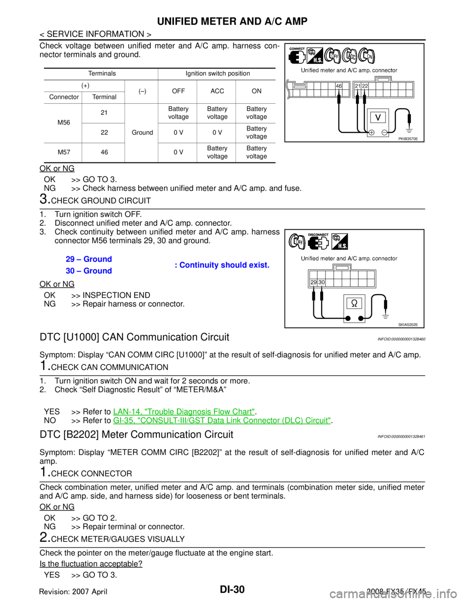
Check voltage between unified meter and A/C amp. harness con-
nector terminals and ground.
OK or NG
OK >> GO TO 3.
NG >> Check harness between unified meter and A/C amp. and fuse.
3.CHECK GROUND CIRCUIT
1. Turn ignition switch OFF.
2. Disconnect unified meter and A/C amp. connector.
3. Check continuity between unified meter and A/C amp. harness connector M56 terminals 29, 30 and ground.
OK or NG
OK >> INSPECTION END
NG >> Repair harness or connector.
DTC [U1000] CAN Communication CircuitINFOID:0000000001328460
Symptom: Display “CAN COMM CIRC [U1000]” at the re sult of self-diagnosis for unified meter and A/C amp.
1.CHECK CAN COMMUNICATION
1. Turn ignition switch ON and wait for 2 seconds or more.
2. Check “Self Diagnostic Result” of “METER/M&A”
YES >> Refer to LAN-14, "
Trouble Diagnosis Flow Chart".
NO >> Refer to GI-35, "
CONSULT-III/GST Data Link Connector (DLC) Circuit".
DTC [B2202] Meter Communication CircuitINFOID:0000000001328461
Symptom: Display “METER COMM CI RC [B2202]” at the result of self-diagnosis for unified meter and A/C
amp.
1.CHECK CONNECTOR
Check combination meter, unified meter and A/C amp. and terminals (combination meter side, unified meter
and A/C amp. side, and harness side) for looseness or bent terminals.
OK or NG
OK >> GO TO 2.
NG >> Repair terminal or connector.
2.CHECK METER/GAUGES VISUALLY
Check the pointer on the meter/gauge fluctuate at the engine start.
Is the fluctuation acceptable?
YES >> GO TO 3.
Terminals Ignition switch position
(+) (–) OFF ACC ON
Connector Terminal
M56 21
Ground Battery
voltage Battery
voltage Battery
voltage
22 0 V 0 V Battery
voltage
M57 46 0 V Battery
voltage Battery
voltage
PKIB3570E
29 – Ground : Continuity should exist.
30 – Ground
SKIA5202E
3AA93ABC3ACD3AC03ACA3AC03AC63AC53A913A773A893A873A873A8E3A773A983AC73AC93AC03AC3
3A893A873A873A8F3A773A9D3AAF3A8A3A8C3A863A9D3AAF3A8B3A8C
Page 1177 of 3924
WARNING CHIMEDI-51
< SERVICE INFORMATION >
C
DE
F
G H
I
J
L
M A
B
DI
N
O P
WARNING CHIME
System DescriptionINFOID:0000000001328473
Buzzer for warning chime system is installed in the combination meter.
The buzzer sounds when the combination meter receives buzzer output signal from each unit through uni- fied meter and A/C amp.
POWER SUPPLY AND CIRCUIT
Power is supplied at all times
through 50A fusible link (letter M, located in the fuse and fusible link block)
to BCM terminal 55,
through 15A fuse [No. 22, located in the fuse block (J/B)]
to key switch and ignition knob switch terminal 3 (with Intelligent Key), and
to key switch terminal 2 (without Intelligent Key), and
to BCM terminal 42,
through 10A fuse [No. 38, located in the fuse and fusible link block (with Intelligent Key)]
to key switch and ignition knob switch terminal 1,
through 10A fuse [No. 19, located in the fuse block (J/B)]
to unified meter and A/C amp. terminal 21, and
to combination meter terminal 8.
When ignition switch is in ON or START position, power is supplied
through 15A fuse [No. 1, located in the fuse block (J/B)]
to BCM terminal 38,
through 10A fuse [No. 12, located in the fuse block (J/B)]
to unified meter and A/C amp. terminal 22,
through 10A fuse [No. 14, located in the fuse block (J/B)]
to combination meter terminal 7.
Ground is supplied
to BCM terminals 49 and 52,
to unified meter and A/C amp. terminals 29 and 30, and
to combination meter terminals 5, 6 and 15
through grounds M35, M45 and M85.
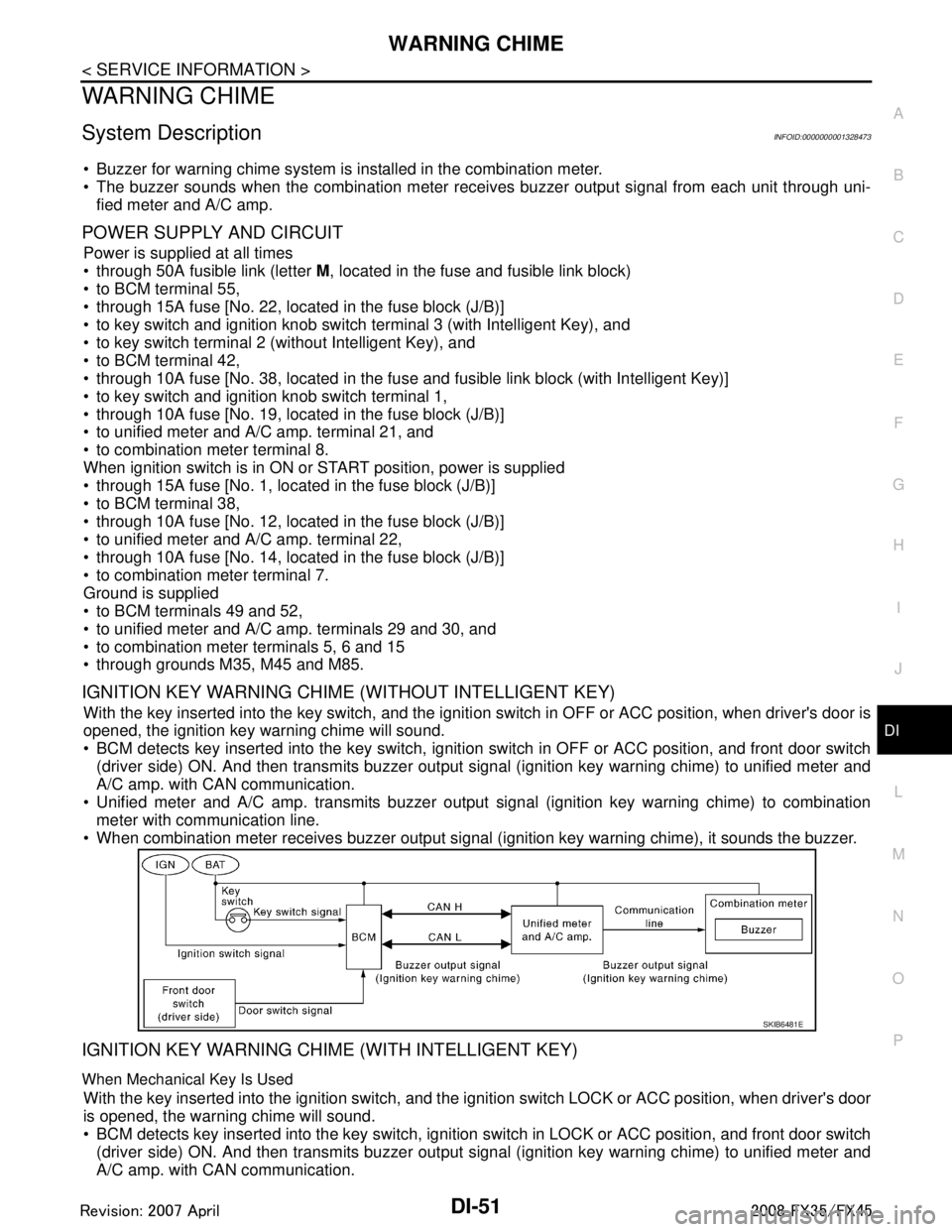
IGNITION KEY WARNING CHIME (WITHOUT INTELLIGENT KEY)
With the key inserted into the key switch, and the igniti on switch in OFF or ACC position, when driver's door is
opened, the ignition key warning chime will sound.
BCM detects key inserted into the key switch, igniti on switch in OFF or ACC position, and front door switch
(driver side) ON. And then transmits buzzer output signal (ignition key warning chime) to unified meter and
A/C amp. with CAN communication.
Unified meter and A/C amp. transmits buzzer output signal (ignition key warning chime) to combination
meter with communication line.
When combination meter receives buzzer output signal (ignition key warning chime), it sounds the buzzer.
IGNITION KEY WARNING CHIME (WITH INTELLIGENT KEY)
When Mechanical Key Is Used
With the key inserted into the ignition switch, and the i gnition switch LOCK or ACC position, when driver's door
is opened, the warning chime will sound.
BCM detects key inserted into the key switch, ignition switch in LOCK or ACC position, and front door switch
(driver side) ON. And then transmits buzzer output signal (ignition key warning chime) to unified meter and
A/C amp. with CAN communication.
SKIB6481E
3AA93ABC3ACD3AC03ACA3AC03AC63AC53A913A773A893A873A873A8E3A773A983AC73AC93AC03AC3
3A893A873A873A8F3A773A9D3AAF3A8A3A8C3A863A9D3AAF3A8B3A8C
Page 1196 of 3924
DI-70
< SERVICE INFORMATION >
LANE DEPARTURE WARNING SYSTEM
- The LDW switch must be pushed to turn on the system.
To the change modes- Push and hold LDW switch for more than 4 seconds, when LDW system ON indicator is off.
- Then LDW chime sounds and blinking of LDW system ON indicator informs that the mode change is com-
pleted.
Temporary disabled status at high temperature
- If the vehicle is parked in direct sunlight under high temperature conditions [approximately over 104 °F
(40 °C)] and then started, the LDW system may sound a ch ime and cancel automatically. Then LDW system
ON indicator will blink.
- When the interior temperature is reduced, the system will resume to operate automatically and the LDW sys-
tem ON indicator illuminates.
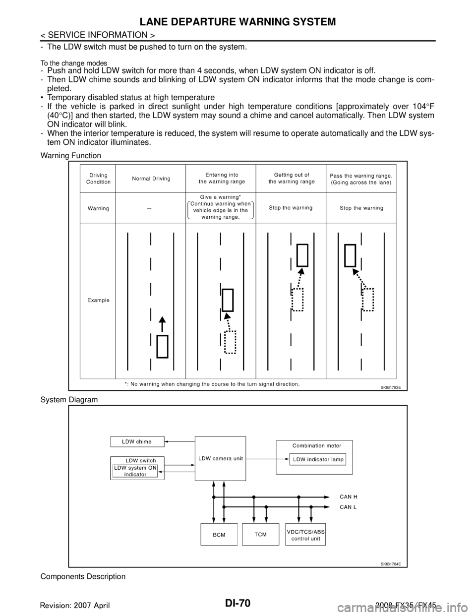
Warning Function
System Diagram
Components Description
SKIB1783E
SKIB1784E
3AA93ABC3ACD3AC03ACA3AC03AC63AC53A913A773A893A873A873A8E3A773A983AC73AC93AC03AC3
3A893A873A873A8F3A773A9D3AAF3A8A3A8C3A863A9D3AAF3A8B3A8C
Page 1197 of 3924
LANE DEPARTURE WARNING SYSTEMDI-71
< SERVICE INFORMATION >
C
DE
F
G H
I
J
L
M A
B
DI
N
O P
NOTE:
*: This indicates in a few seconds for the system check during ignition switch ON.
POWER SUPPLY AND GROUND CIRCUIT
With the ignition switch in the ON or START position, power is supplied
through 10A fuse [No. 12, located in the fuse block (J/B)]
to LDW camera unit terminal 1.
Ground is supplied
to LDW camera unit terminals 6 and 12
through grounds M45, M85 and M35.
Action TestINFOID:0000000001328494
LDW SYSTEM RUNNING TEST
WARNING:
Be careful when performing road test.
Understand “Precautions” and “System Description” well before the road test. Refer to DI-69, "
Pre-
caution for Lane Departure Warning (LDW) system" and DI-69, "System Description".
Function Check
Check the LDW system operation according to the c ondition that the warning function works. Refer to DI-69,
"System Description".
Camera Aiming AdjustmentINFOID:0000000001328495
OUTLINE
Adjust the camera aiming every time the LDW camera unit is removed or installed.
CAUTION:
Place the vehicle on the level ground when the camera aiming adjustment is operated.
Follow the CONSULT-III when ad justing the camera aiming. (Camera aiming adjustment cannot be
operated without CONSULT-III.)
PREPARATION
Keep all tires inflated to correct pressures. Adjust the tire pressure to the specified pressure value.
There is no-load in vehicle. Check if coolant, engine oil are filled up to correct level and fuel tank is full.
Shift the gear into “P” position and release the parking brake.
Clean the windshield.
NOTE:
Do not place anything reflective on t he upper surface of instrument panel.
TARGET SETTING
Preparation Aiming Adjustment Jig
Component Description
LDW camera unit Detects the lane marker by the built-in camera, gives judgement for the warning according to the result
of detection and signals from each unit, and transmits the operation signal to LDW chime and LDW
indicator lamp.
LDW switch Selects ON/OFF of the system.
Indicates ON/OFF of the signal with LDW system ON indicator.
LDW chime Gives a warning chime according to the direction from LDW camera unit.
LDW indicator lamp Installed in combination meter, and indicates the system condition.
Blinks when LDW system is functioning to alert the driver.
Stays on when LDW system is malfunctioning.
*
BCM Transmits turn indicator signal to LDW camera unit with CAN communication signal.
ABS actuator and electric unit
(control unit)
Transmits vehicle speed signal to LDW camera unit with CAN communication signal.
TCM Transmits vehicle speed signal to LDW camera unit with CAN communication signal. (For detecting
incorrect speed.)
3AA93ABC3ACD3AC03ACA3AC03AC63AC53A913A773A893A873A873A8E3A773A983AC73AC93AC03AC3
3A893A873A873A8F3A773A9D3AAF3A8A3A8C3A863A9D3AAF3A8B3A8C
Page 1201 of 3924
LANE DEPARTURE WARNING SYSTEMDI-75
< SERVICE INFORMATION >
C
DE
F
G H
I
J
L
M A
B
DI
N
O P
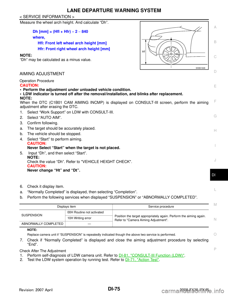
Measure the wheel arch height. And calculate “Dh”.
NOTE:
“Dh” may be calculated as a minus value.
AIMING ADJUSTMENT
Operation Procedure
CAUTION:
Perform the adjustment under unloaded vehicle condition.
LDW indicator is turned off after the remo val/installation, and blinks after replacement.
NOTE:
When the DTC (C1B01 CAM AIMING INCMP) is disp layed on CONSULT-III screen, perform the aiming
adjustment after erasing the DTC.
1. Select “Work Support” on LDW with CONSULT-III.
2. Select “AUTO AIM”.
3. Confirm following.
a. The target should be accurately placed.
b. The vehicle should be stopped.
4. Select “Start” to perform aiming.
CAUTION:
Never Select “Start” when the target is not placed.
5. Input “Dh”, and then select “Start”. NOTE:
Check the value “Dh”. Refer to "VEHICLE HEIGHT CHECK".
CAUTION:
Never change “Ht” and “Dt”.
6. Check it display item.
a. “Normally Completed” is displayed, then selecting “Completion”.
b. Perform the following services when displa yed “SUSPENSION” or “ABNORMALLY COMPLETED”.
NOTE:
Replace camera unit if “SUSPENSION” is repeatedly indicated though the above tw o service is performed.
7. Check if “Normally Completed” is displayed and close the aiming adjustment procedure by selecting
“End”.
Check After The Adjustment
1. Perform self-diagnosis of LDW camera unit. Refer to DI-81, "CONSULT-III Function (LDW)".
2. Test the LDW system operation by running test. Refer to DI-71, "
Action Test".
Dh [mm] = (Hfl + Hfr)
÷ 2 − 840
where, Hfl: Front left wheel arch height [mm]
Hfr: Front right wheel arch height [mm]
SKIB3164E
Displays item Service procedure
SUSPENSION 00H Routine not activated
Position the target appropriately again. Perform the aiming again.
Refer to "Camera Aiming Adjustment".
10H Writing error
ABNORMALLY COMPLETED —
3AA93ABC3ACD3AC03ACA3AC03AC63AC53A913A773A893A873A873A8E3A773A983AC73AC93AC03AC3
3A893A873A873A8F3A773A9D3AAF3A8A3A8C3A863A9D3AAF3A8B3A8C
Page 1208 of 3924
![INFINITI FX35 2008 Service Manual
DI-82
< SERVICE INFORMATION >
LANE DEPARTURE WARNING SYSTEM
NOTE:
When a DTC is detected, the LDW system dose not operate.
When the DTC except “ABNRML TEMP DETECT [C1B03] ” is detected, the INFINITI FX35 2008 Service Manual
DI-82
< SERVICE INFORMATION >
LANE DEPARTURE WARNING SYSTEM
NOTE:
When a DTC is detected, the LDW system dose not operate.
When the DTC except “ABNRML TEMP DETECT [C1B03] ” is detected, the](/manual-img/42/57017/w960_57017-1207.png)
DI-82
< SERVICE INFORMATION >
LANE DEPARTURE WARNING SYSTEM
NOTE:
When a DTC is detected, the LDW system dose not operate.
When the DTC except “ABNRML TEMP DETECT [C1B03] ” is detected, the LDW indicator lamp turns ON.
When the DTC “ABNRML TEMP DETECT [C1B03] ” is detected, the LDW system ON indicator lamp blinks.
DATA MONITOR
Display Item
ACTIVE TEST
CAUTION:
Never perform the active test while driving.
Active test cannot be started while LDW indicator lamp is illuminated.
Display item [Code] Malfunctions detected where... Reference
page
CAMERA UNIT MALF [C1B00] LDW camera unit internal malfunction DI-85
CAM AIMING INCMP [C1B01] LDW camera aiming is not adjusted. DI-85
VHCL SPD DATA MALF [C1B02]LDW camera unit detected different vehicle speed signal from TCM and ABS ac-
tuator and electric unit (control unit). DI-85
ABNRML TEMP DETECT [C1B03] Temperature around LDW camera unit is excessively high.
DI-86
CAN COMM CIRCUIT [U1000] LDW camera unit detected CAN communication malfunction. DI-86
CONTROL UNIT (CAN) [U1010] LDW camera unit detected internal CAN communication circuit malfunction. DI-86
Monitored Item [unit] Description
VHCL SPD SE [km/h] or [mph] Displays vehicle speed calculated by LDW camera unit through CAN communication [ABS
actuator and electric unit (control unit) transmits wheel sensor signal through CAN communi-
cation].
VHCL SPD AT [km/h] or [mph] Displays vehicle speed calculated from A/T vehicle speed sensor by LDW camera unit
through CAN communication (TCM transmits A/T vehicle speed sensor signal through CAN
communication).
FCTRY AIM YAW [deg] Displays camera unit installation condition.
FCTRY AIM ROL [deg] Displays camera unit installation condition.
FCTRY AIM PIT [deg] Displays camera unit installation condition.
XOFFSET [pixel] Displays camera unit installation condition.
MAIN SW [On/Off] Displays [On/Off] status as judged from LDW switch signal.
SW ON LAMP [On/Off] Displays [On/Off] status of LDW system ON indicator signal output.
INDICATE LAMP [On/Off] Displays [On/Off] status of LDW indicator signal output.
BUZZER OUTPUT [On/Off] Displays [On/Off] status of LDW chime operation signal output.
LDW INACCURAT [On/Off] Displays LDW camera unit status.
TURN SIGNAL [Off/LH/RH] Displays “Tur n signal” status, determined from BCM thro ugh CAN communication.
LANE DETCT LH [On/Off] Displays left lane marker is detected.
LANE DETCT RH [On/Off] Displays right lane marker is detected.
CROSS LANE LH [On/Off] Displays vehicle is crossing left lane.
CROSS LANE RH [On/Off] Displays vehicle is crossing right lane.
WARN LANE LH [On/Off] Displays warning for left lane.
WARN LANE RH [On/Off] Displays warning for right lane.
VALID POS LH [VLD/INVLD] Displays lateral position for left lane marker is valid.
VALID POS RH [VLD/INVLD] Displays lateral position for right lane marker is valid.
AIMING DONE [OK/NG] Displa ys camera aiming done.
AIMING RESULT [OK/NOK] Disp lays camera aiming result.
3AA93ABC3ACD3AC03ACA3AC03AC63AC53A913A773A893A873A873A8E3A773A983AC73AC93AC03AC3
3A893A873A873A8F3A773A9D3AAF3A8A3A8C3A863A9D3AAF3A8B3A8C
Page 1209 of 3924
LANE DEPARTURE WARNING SYSTEMDI-83
< SERVICE INFORMATION >
C
DE
F
G H
I
J
L
M A
B
DI
N
O P
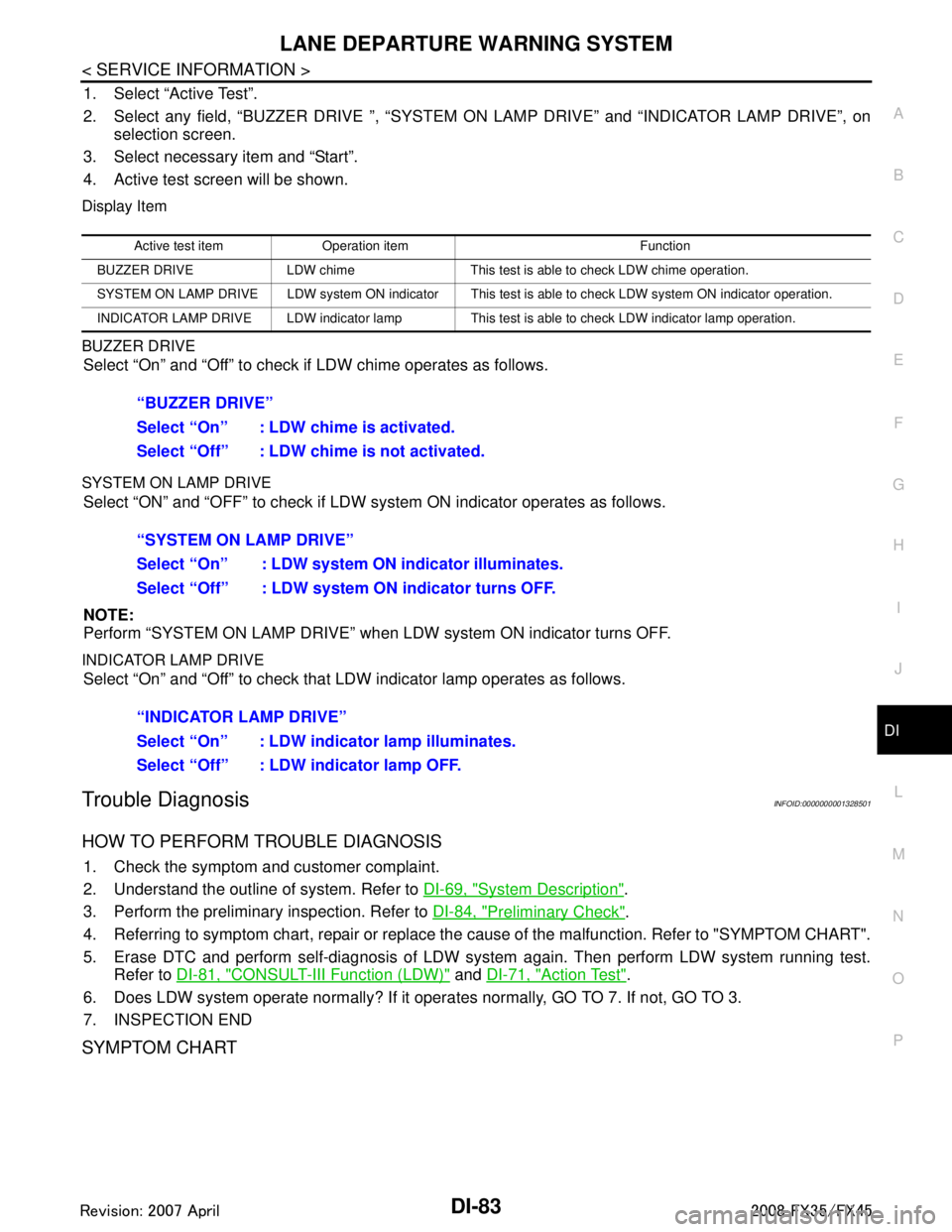
1. Select “Active Test”.
2. Select any field, “BUZZER DRIVE ”, “SYSTEM ON LAMP DRIVE” and “INDICATOR LAMP DRIVE”, on
selection screen.
3. Select necessary item and “Start”.
4. Active test screen will be shown.
Display Item
BUZZER DRIVE
Select “On” and “Off” to check if LDW chime operates as follows.
SYSTEM ON LAMP DRIVE
Select “ON” and “OFF” to check if LDW s ystem ON indicator operates as follows.
NOTE:
Perform “SYSTEM ON LAMP DRIVE” when LDW system ON indicator turns OFF.
INDICATOR LAMP DRIVE
Select “On” and “Off” to check that LDW indicator lamp operates as follows.
Trouble DiagnosisINFOID:0000000001328501
HOW TO PERFORM TROUBLE DIAGNOSIS
1. Check the symptom and customer complaint.
2. Understand the outline of system. Refer to DI-69, "
System Description".
3. Perform the preliminary inspection. Refer to DI-84, "
Preliminary Check".
4. Referring to symptom chart, repair or replace the cause of the malfunction. Refer to "SYMPTOM CHART".
5. Erase DTC and perform self-diagnosis of LDW sys tem again. Then perform LDW system running test.
Refer to DI-81, "
CONSULT-III Function (LDW)" and DI-71, "Action Test".
6. Does LDW system operate normally? If it oper ates normally, GO TO 7. If not, GO TO 3.
7. INSPECTION END
SYMPTOM CHART
Active test item Operation item Function
BUZZER DRIVE LDW chime This test is able to check LDW chime operation.
SYSTEM ON LAMP DRIVE LDW system ON indicator This test is able to check LDW system ON indicator operation.
INDICATOR LAMP DRIVE LDW indicator lamp This test is able to check LDW indicator lamp operation.
“BUZZER DRIVE”
Select “On” : LDW chime is activated.
Select “Off” : LDW chime is not activated.
“SYSTEM ON LAMP DRIVE”
Select “On” : LDW system ON indicator illuminates.
Select “Off” : LDW system ON indicator turns OFF.
“INDICATOR LAMP DRIVE”
Select “On” : LDW indicator lamp illuminates.
Select “Off” : LDW indicator lamp OFF.
3AA93ABC3ACD3AC03ACA3AC03AC63AC53A913A773A893A873A873A8E3A773A983AC73AC93AC03AC3
3A893A873A873A8F3A773A9D3AAF3A8A3A8C3A863A9D3AAF3A8B3A8C
Page 1222 of 3924

DI-96
< SERVICE INFORMATION >
COMPASS
if an aftermarket (i.e., non original equipment) antenna with a magnetic base is attached to the vehicle. Cali-
brate the mirror compass if the display shows onl y one direction or a limited number of directions.
NOTE:
If “magnetic hats” are used in the dealership for vehicle identification, remove the hat from the vehicle before
performing the following steps. Do NOT put the hat back on the vehicle after the procedure is completed.
Drive the vehicle to an open level area; away from large metallic objects, structures, and overhead power
lines.
Turn off “non-essential” electrical accessories (r ear window defrost, heater/air conditioning, wipers) and
close the doors.
1. Verify the correct compass zone setting for the geographical location. Refer to DI-95, "
Zone Variation Set-
ting Procedure".
2. Press and hold the inside mirror switch for more than 9 seconds.
3. “C” is displayed on the compass display, when calibration starts.
4. Drive slowly [less than 8 km/h (5 mph)] in a circle until the “C / CAL” is replaced with primary headings (N,
NE, E, SE, S, SW, W, or NW).
NOTE:
This will require driving at least 2 complete 360 degree circles; 3 complete circles may be required.
5. The compass calibration procedure is now complete. The compass should operate normally. NOTE:
If at any time the compass continually displays the in correct direction or the reading is erratic or locked,
repeat the calibration procedure.
3AA93ABC3ACD3AC03ACA3AC03AC63AC53A913A773A893A873A873A8E3A773A983AC73AC93AC03AC3
3A893A873A873A8F3A773A9D3AAF3A8A3A8C3A863A9D3AAF3A8B3A8C