2008 INFINITI FX35 service indicator
[x] Cancel search: service indicatorPage 3181 of 3924
TURN SIGNAL AND HAZARD WARNING LAMPSLT-79
< SERVICE INFORMATION >
C
DE
F
G H
I
J
L
M A
B
LT
N
O P
When the turn signal switch is moved to the left positi on, BCM output turn signal from BCM terminal 45, inter-
preting it as turn signal is ON.
Connected from BCM terminal 45 to front combination lamp LH terminal 4.
Turn signal lamp turns ON
through front combination lamp LH terminal 8
to grounds E21, E50 and E51.
Connected from BCM terminal 45 to rear co mbination lamp control unit terminal 4.
Rear turn signal (LED) turns ON
through rear combination lamp control unit terminal 11
to rear combination lamp LH terminal 3,
through rear combination lamp LH terminal 4
to rear combination lamp control unit terminal 10.
BCM sends signal to the unified meter and A/C amp. through CAN communication, and turns ON turn signal
indicator lamp with combination meter.
When rear turn signal lamp (LED) does not turn ON, rear combination lamp control unit sends signal to combi-
nation meter. And then unified meter and A/C amp. ends turn LED burnout status signal to BCM through CAN
communication lines for speeding up turn signal blinking.
RH Turn Signal Lamp
When the turn signal switch is moved to right position, BCM output turn signal from BCM terminal 46, interpret-
ing it as turn signal is ON.
Connected from BCM terminal 46 to front combination lamp RH terminal 4.
Turn signal lamp turns ON
through front combination lamp RH terminal 8
to grounds E21, E50 and E51.
Connected form BCM terminal 46 to rear co mbination lamp control unit terminal 5.
Rear turn signal (LED) turns ON
through rear combination lamp control unit terminal 9
to rear combination lamp RH terminal 3,
through rear combination lamp RH terminal 4
to rear combination lamp control unit terminal 8.
BCM sends signal to the unified meter and A/C amp. through CAN communication, and turns ON turn signal
indicator lamp with combination meter.
When rear turn signal lamp (LED) does not turn ON, rear combination lamp control unit sends signal to combi-
nation meter. And then unified meter and A/C amp. ends turn LED burnout status signal to BCM through CAN
communication lines for speeding up turn signal blinking.
HAZARD LAMP OPERATION
When the hazard switch is depressed, BCM output turn signal from BCM terminals 45 and 46, interpreting it as
turn signal is ON.
Connected from BCM terminal 45 and 46 to front combination lamp RH and LH terminals 4.
Turn signal lamp turns ON
through front combination lamp RH and LH terminals 8
to grounds E21, E50 and E51.
Connected form BCM terminals 45 and 46 to rear combination lamp control unit terminals 4 and 5.
Rear turn signal (LED) turns ON
through rear combination lamp control unit terminal 11
to rear combination lamp LH terminal 3,
through rear combination lamp LH terminal 4
to rear combination lamp control unit terminal 10,
through rear combination lamp control unit terminal 9
to rear combination lamp RH terminal 3,
through rear combination lamp RH terminal 4
to rear combination lamp control unit terminal 8.
And hazard switch is depr essed, ground is supplied
to hazard switch terminal 2
through BCM terminal 29,
to grounds M35, M45 and M85
through hazard switch terminal 1.
BCM sends signal to the unified meter and A/C amp. through CAN communication, and turns ON turn signal
indicator lamp with combination meter.
3AA93ABC3ACD3AC03ACA3AC03AC63AC53A913A773A893A873A873A8E3A773A983AC73AC93AC03AC3
3A893A873A873A8F3A773A9D3AAF3A8A3A8C3A863A9D3AAF3A8B3A8C
Page 3182 of 3924
LT-80
< SERVICE INFORMATION >
TURN SIGNAL AND HAZARD WARNING LAMPS
When rear turn signal lamp (LED) does not turn ON, rear combination lamp control unit sends s\
ignal to combi-
nation meter. And then unified meter and A/C amp. ends turn LED burnout status signal to BCM through CAN
communication lines for speeding up turn signal blinking.
REMOTE CONTROL ENTRY SYSTEM OPERATION
When the remote control entry system is triggered by i nput from key fob, BCM output turn signal from BCM
terminals 45 and 46, interpreting it as turn signal is ON.
Connected from BCM terminals 45 and 46 to front combination lamp RH and LH terminals 4.
Turn signal lamp turns ON
through front combination lamp RH and LH terminals 8
to grounds E21, E50 and E51.
Connected form BCM terminals 45 and 46 to rear combination lamp control unit terminals 4 and 5.
Rear turn signal (LED) turns ON
through rear combination lamp control unit terminal 11
to rear combination lamp LH terminal 3,
through rear combination lamp LH terminal 4
to rear combination lamp control unit terminal 10,
through rear combination lamp control unit terminal 9
to rear combination lamp RH terminal 3,
through rear combination lamp RH terminal 4
to rear combination lamp control unit terminal 8.
BCM sends signal to the unified meter and A/C amp. through the CAN communication, and turns ON turn sig-
nal indicator lamp with combination meter.
With power and input supplied, BCM controls the flashing of hazard warning lamps when key fob is used to
activate remote control entry system.
COMBINATION SWITCH READING FUNCTION
Refer to BCS-4, "System Description".
CAN Communication System DescriptionINFOID:0000000001328345
CAN (Controller Area Network) is a serial communication line for real time application. It is an on-vehicle mul-
tiplex communication line with high data communication s peed and excellent error detection ability. Many elec-
tronic control units are equipped onto a vehicle, and each control unit shares information and links with other
control units during operation (not independent). In CA N communication, control units are connected with 2
communication lines (CAN H line, CAN L line) allowing a high rate of information transmission with less wiring.
Each control unit transmits/receives data but selectively reads required data only.
CAN Communication UnitINFOID:0000000001328346
Refer to LAN-43, "CAN System Specification Chart".
3AA93ABC3ACD3AC03ACA3AC03AC63AC53A913A773A893A873A873A8E3A773A983AC73AC93AC03AC3
3A893A873A873A8F3A773A9D3AAF3A8A3A8C3A863A9D3AAF3A8B3A8C
Page 3336 of 3924
ENGINE MAINTENANCE (VK45DE ENGINE)MA-19
< SERVICE INFORMATION >
C
DE
F
G H
I
J
K
M A
B
MA
N
O P
ENGINE MAINTENANCE (VK45DE ENGINE)
Checking Drive BeltsINFOID:0000000001328909
WARNING:
Be sure to perform when the engine is stopped.
Remove air duct (inlet) when inspecting drive belt for alternator, water pump and A/C compressor.
Remove front engine undercover with power tool when inspecting power steering oil pump belt.
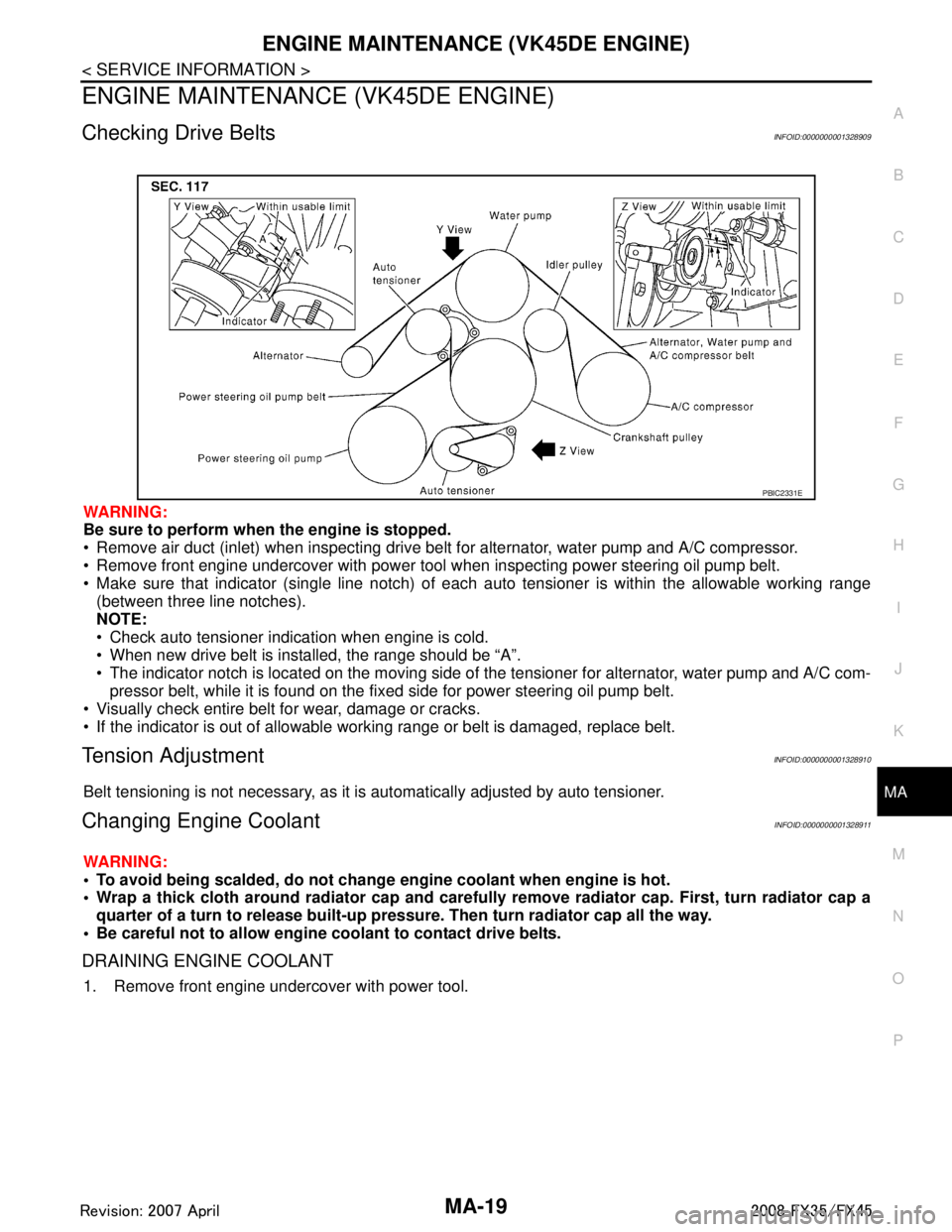
Make sure that indicator (single line notch) of eac h auto tensioner is within the allowable working range
(between three line notches).
NOTE:
Check auto tensioner indication when engine is cold.
When new drive belt is installed, the range should be “A”.
The indicator notch is located on the moving side of the tensioner for alternator, water pump and A/C com-
pressor belt, while it is found on the fi xed side for power steering oil pump belt.
Visually check entire belt for wear, damage or cracks.
If the indicator is out of allowable working range or belt is damaged, replace belt.
Tension AdjustmentINFOID:0000000001328910
Belt tensioning is not necessary, as it is automatically adjusted by auto tensioner.
Changing Engine CoolantINFOID:0000000001328911
WARNING:
To avoid being scalded, do not change engine coolant when engine is hot.
Wrap a thick cloth around radiator cap and carefully remove radiator cap. First, turn radiator cap a
quarter of a turn to release built-up pressu re. Then turn radiator cap all the way.
Be careful not to allow engine coolant to contact drive belts.
DRAINING ENGINE COOLANT
1. Remove front engine undercover with power tool.
PBIC2331E
3AA93ABC3ACD3AC03ACA3AC03AC63AC53A913A773A893A873A873A8E3A773A983AC73AC93AC03AC3
3A893A873A873A8F3A773A9D3AAF3A8A3A8C3A863A9D3AAF3A8B3A8C
Page 3347 of 3924
MA-30
< SERVICE INFORMATION >
CHASSIS AND BODY MAINTENANCE
2. Check oil level.
Balancing Wheels (Bonding Weight Type)INFOID:0000000001328926
REMOVAL
Using releasing agent, remove double-faced adhesive tape from the road wheel.
CAUTION:
Be careful not to scratch th e road wheel during removal.
After removing double-faced adhesive tape, wi pe clean traces of releasing agent from the road
wheel.
WHEEL BALANCE ADJUSTMENT
If a tire balance machine has adhesion balance weight mode settings and drive-in weight mode setting,
select and adjust a drive-in weight mode suitable for road wheels.
1. Set road wheel on tire balance machine using the center hole as a guide. Start the tire balance machine.
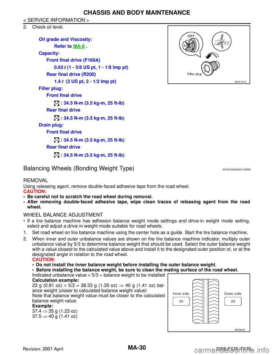
2. When inner and outer unbalance values are shown on the tire balance machine indicator, multiply outer unbalance value by 5/3 to determine balance weight t hat should be used. Select the outer balance weight
with a value closest to the calculated value above and inst all it to the designated outer position of, or at the
designated angle in relation to the road wheel.
CAUTION:
Do not install the inner balance weight before installing the outer balance weight.
Before installing the balance weight, be sure to clean the mating surface of the road wheel.
Indicated unbalance value × 5/3 = balance weight to be installed
Calculation example:
23 g (0.81 oz) × 5/3 = 38.33 g (1.35 oz) ⇒ 40 g (1.41 oz) bal-
ance weight (closer to calculated balance weight value)
Note that balance weight value must be closer to the calculated
balance weight value.
Example:
37.4 ⇒ 35 g (1.23 oz)
37.5 ⇒ 40 g (1.41 oz)
Oil grade and Viscosity:
Refer to MA-9
.
Capacity: Front final drive (F160A)
0.65 (1 - 3/8 US pt, 1 - 1/8 lmp pt)
Rear final drive (R200)
1.4 (3 US pt, 2 - 1/2 lmp pt)
Filler plug: Front final drive
: 34.5 N-m (3.5 kg-m, 25 ft-lb)
Rear final drive
: 34.5 N-m (3.5 kg-m, 25 ft-lb)
Drain plug: Front final drive
: 34.5 N-m (3.5 kg-m, 25 ft-lb)
Rear final drive
: 34.5 N-m (3.5 kg-m, 25 ft-lb)
SDIA1151E
SMA054D
:
Page 3425 of 3924
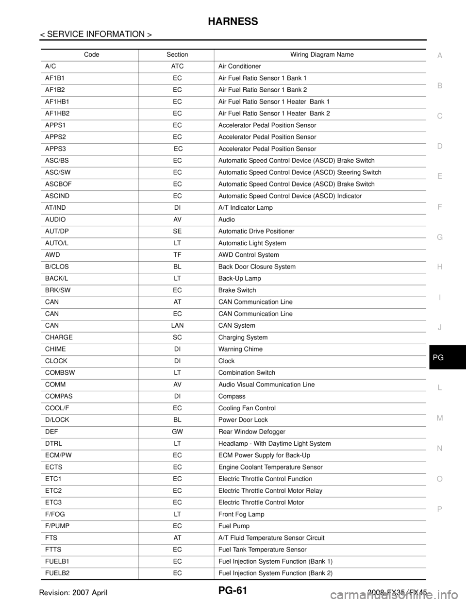
HARNESSPG-61
< SERVICE INFORMATION >
C
DE
F
G H
I
J
L
M A
B
PG
N
O P
Code Section Wiring Diagram Name
A/C ATC Air Conditioner
AF1B1 EC Air Fuel Ratio Sensor 1 Bank 1
AF1B2 EC Air Fuel Ratio Sensor 1 Bank 2
AF1HB1 EC Air Fuel Ratio Sensor 1 Heater Bank 1
AF1HB2 EC Air Fuel Ratio Sensor 1 Heater Bank 2
APPS1 EC Accelerator Pedal Position Sensor
APPS2 EC Accelerator Pedal Position Sensor
APPS3 EC Accelerator Pedal Position Sensor
ASC/BS EC Automatic Speed Control Device (ASCD) Brake Switch
ASC/SW EC Automatic Speed Control Device (ASCD) Steering Switch
ASCBOF EC Automatic Speed Control Device (ASCD) Brake Switch
ASCIND EC Automatic Speed Contro l Device (ASCD) Indicator
AT/IND DI A/T Indicator Lamp
AUDIO AV Audio
AUT/DP SE Automatic Drive Positioner
AUTO/L LT Automatic Light System
AWD TF AWD Control System
B/CLOS BL Back Door Closure System
BACK/L LT Back-Up Lamp
BRK/SW EC Brake Switch
CAN AT CAN Communication Line
CAN EC CAN Communication Line
CAN LAN CAN System
CHARGE SC Charging System
CHIME DI Warning Chime
CLOCK DI Clock
COMBSW LT Combination Switch
COMM AV Audio Visual Communication Line
COMPAS DI Compass
COOL/F EC Cooling Fan Control
D/LOCK BL Power Door Lock
DEF GW Rear Window Defogger
DTRL LT Headlamp - With Daytime Light System
ECM/PW EC ECM Power Supply for Back-Up
ECTS EC Engine Coolant Temperature Sensor
ETC1 EC Electric Throttle Control Function
ETC2 EC Electric Throttle Control Motor Relay
ETC3 EC Electric Throttle Control Motor
F/FOG LT Front Fog Lamp
F/PUMP EC Fuel Pump
FTS AT A/T Fluid Temperature Sensor Circuit
FTTS EC Fuel Tank Temperature Sensor
FUELB1 EC Fuel Injection System Function (Bank 1)
FUELB2 EC Fuel Injection System Function (Bank 2)
3AA93ABC3ACD3AC03ACA3AC03AC63AC53A913A773A893A873A873A8E3A773A983AC73AC93AC03AC3
3A893A873A873A8F3A773A9D3AAF3A8A3A8C3A863A9D3AAF3A8B3A8C
Page 3561 of 3924
REAR FINAL DRIVE ASSEMBLYRFD-19
< SERVICE INFORMATION >
CEF
G H
I
J
K L
M A
B
RFD
N
O P
2. Remove side flanges.
3. Rotate drive pinion back and forth 2 to 3 times to check for unusual noise and rotation malfunction.
4. Rotate drive pinion at least 20 times to check for smooth operation of the bearing.
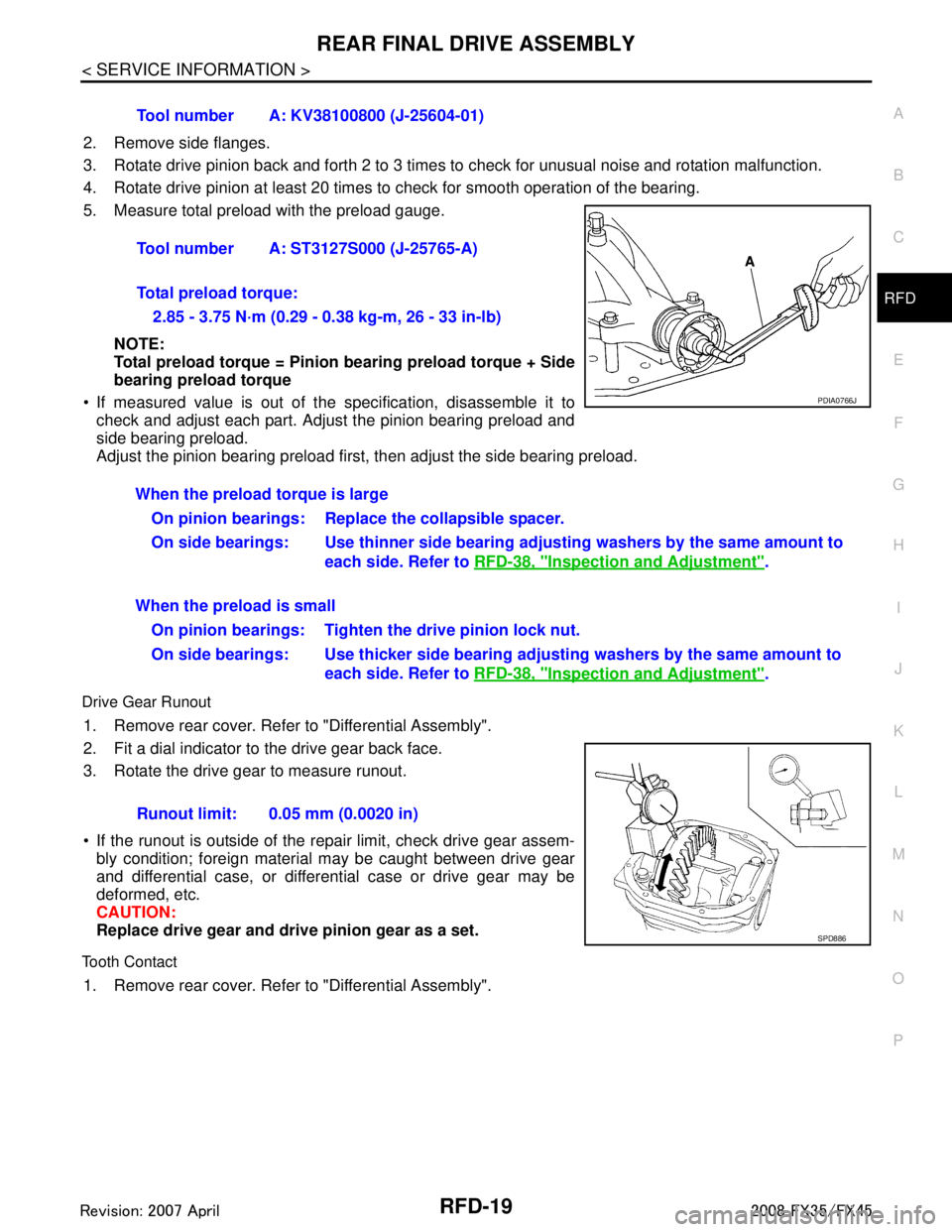
5. Measure total preload with the preload gauge.
NOTE:
Total preload torque = Pinion bearing preload torque + Side
bearing preload torque
If measured value is out of the specification, disassemble it to
check and adjust each part. Adjust the pinion bearing preload and
side bearing preload.
Adjust the pinion bearing preload first, then adjust the side bearing preload.
Drive Gear Runout
1. Remove rear cover. Refer to "Differential Assembly".
2. Fit a dial indicator to the drive gear back face.
3. Rotate the drive gear to measure runout.
If the runout is outside of the repair limit, check drive gear assem- bly condition; foreign material may be caught between drive gear
and differential case, or differential case or drive gear may be
deformed, etc.
CAUTION:
Replace drive gear and dri ve pinion gear as a set.
Tooth Contact
1. Remove rear cover. Refer to "Differential Assembly".Tool number A: KV38100800 (J-25604-01)
Tool number A: ST3127S000 (J-25765-A)
Total preload torque:
2.85 - 3.75 N·m (0.29 - 0.38 kg-m, 26 - 33 in-lb)
PDIA0766J
When the preload torque is largeOn pinion bearings: Replace the collapsible spacer.
On side bearings: Use thinner side bearing adjusting washers by the same amount to
each side. Refer to RFD-38, "
Inspection and Adjustment".
When the preload is small On pinion bearings: Tighten the drive pinion lock nut.
On side bearings: Use thicker side bearing adjusting washers by the same amount to
each side. Refer to RFD-38, "
Inspection and Adjustment".
Runout limit: 0.05 mm (0.0020 in)
SPD886
3AA93ABC3ACD3AC03ACA3AC03AC63AC53A913A773A893A873A873A8E3A773A983AC73AC93AC03AC3
3A893A873A873A8F3A773A9D3AAF3A8A3A8C3A863A9D3AAF3A8B3A8C
Page 3563 of 3924
REAR FINAL DRIVE ASSEMBLYRFD-21
< SERVICE INFORMATION >
CEF
G H
I
J
K L
M A
B
RFD
N
O P
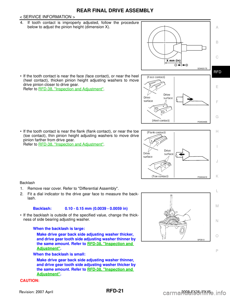
4. If tooth contact is improperly adjusted, follow the procedure
below to adjust the pinion height (dimension X).
If the tooth contact is near the face (face contact), or near the heel (heel contact), thicken pinion height adjusting washers to move
drive pinion closer to drive gear.
Refer to RFD-38, "
Inspection and Adjustment".
If the tooth contact is near the flank (flank contact), or near the toe
(toe contact), thin pinion height adjusting washers to move drive
pinion farther from drive gear.
Refer to RFD-38, "
Inspection and Adjustment".
Backlash
1. Remove rear cover. Refer to "Differential Assembly".
2. Fit a dial indicator to the drive gear face to measure the back-
lash.
If the backlash is outside of the specified value, change the thick- ness of side bearing adjusting washer.
CAUTION:
SDIA0517E
PDIA0440E
PDIA0441E
Backlash: 0.10 - 0.15 mm (0.0039 - 0.0059 in)
When the backlash is large: Make drive gear back side adjusting washer thicker,
and drive gear tooth side adjusting washer thinner by
the same amount. Refer to RFD-38, "
Inspection and
Adjustment".
When the backlash is small: Make drive gear back side adjusting washer thinner,
and drive gear tooth side ad justing washer thicker by
the same amount. Refer to RFD-38, "
Inspection and
Adjustment".
SPD513
3AA93ABC3ACD3AC03ACA3AC03AC63AC53A913A773A893A873A873A8E3A773A983AC73AC93AC03AC3
3A893A873A873A8F3A773A9D3AAF3A8A3A8C3A863A9D3AAF3A8B3A8C
Page 3564 of 3924

RFD-22
< SERVICE INFORMATION >
REAR FINAL DRIVE ASSEMBLY
Never change the total amount of washers as it will change the bearing preload.
Companion Flange Runout
1. Fit a test indicator to the inner side of companion flange (socket
diameter).
2. Rotate companion flange to check for runout.
3. If the runout value is outside t he runout limit, follow the proce-
dure below to adjust.
a. Check for runout while changing the phase between companion flange and drive pinion by 90 ° step, and search for the position
where the runout is the minimum.
b. If the runout value is still outside of the limit after the phase has been changed, possible cause will be an assembly malfunction of drive pinion and pinion bearing and
malfunction of pinion bearing. Check for these items and repair if necessary.
c. If the runout value is still outside of the limit after the check and repair, replace companion flange.
DISASSEMBLY
Differential Assembly
1. Drain gear oil, if necessary.
2. Remove side flange.
3. Remove rear cover mounting bolts.
4. Remove rear cover to insert the seal cutter between gear carrier and rear cover.
CAUTION:
Be careful not to damage the mating surface.
Never insert flat-bladed screwdriver, this way damage the
mating surface.
5. Using two 45 mm (1.77 in) spacers, mount carrier on the attach- ment.Runout limit: 0.08 mm (0.0031 in)
PDIA0490E
Tool number A: KV10111100 (J-37228)
PDIA0756J
Tool number A: KV38100800 (J-25604-01)
PDIA0757J
3AA93ABC3ACD3AC03ACA3AC03AC63AC53A913A773A893A873A873A8E3A773A983AC73AC93AC03AC3
3A893A873A873A8F3A773A9D3AAF3A8A3A8C3A863A9D3AAF3A8B3A8C