2008 INFINITI FX35 ABS
[x] Cancel search: ABSPage 3092 of 3924
![INFINITI FX35 2008 Service Manual
LAN-72
< SERVICE INFORMATION >[CAN]
TROUBLE DIAGNOSIS
OK or NG
OK >> Present error: Check the following items again.
- Decision of CAN system type.
- Not received CONSULT-III data [SELF-DIAG RESUL INFINITI FX35 2008 Service Manual
LAN-72
< SERVICE INFORMATION >[CAN]
TROUBLE DIAGNOSIS
OK or NG
OK >> Present error: Check the following items again.
- Decision of CAN system type.
- Not received CONSULT-III data [SELF-DIAG RESUL](/manual-img/42/57017/w960_57017-3091.png)
LAN-72
< SERVICE INFORMATION >[CAN]
TROUBLE DIAGNOSIS
OK or NG
OK >> Present error: Check the following items again.
- Decision of CAN system type.
- Not received CONSULT-III data [SELF-DIAG RESULTS, CAN DIAG SUPPORT MNTR (“ECU
list” included)].
- Not copied from on-board diagnosis.
- Procedure for detecting root cause.
Past error: Error was detected in the main li ne between the ABS actuator and electric unit (con-
trol unit) and the driver seat control unit.
NG >> Repair the main line between the harness connectors B5 and B8.
ECM Branch Line CircuitINFOID:0000000001328654
INSPECTION PROCEDURE
1.CHECK CONNECTOR
1. Turn the ignition switch OFF.
2. Disconnect the battery cable from the negative terminal.
3. Check the terminals and connectors of the ECM for damage, bend and loose connection (unit side and connector side).
OK or NG
OK >> GO TO 2.
NG >> Repair the terminal and connector.
2.CHECK HARNESS FOR OPEN CIRCUIT
1. Disconnect the connector of ECM.
2. Check the resistance between the ECM harness connector terminals.
OK or NG
OK >> GO TO 3.
NG >> Repair the ECM branch line.
3.CHECK POWER SUPPLY AND GROUND CIRCUIT
Check the power supply and the ground circuit of the ECM. Refer to EC-141, "
Diagnosis Procedure"
(VQ35DE), EC-719, "Diagnosis Procedure" (VK45DE).
OK or NG
OK >> Present error: Replace the ECM. Refer to EC-100, "Engine Control Component Parts Loca-
tion"(VQ35DE), EC-677, "Engine Control Component Parts Location" (VK45DE).
Past error: Error was detected in the ECM branch line.
NG >> Repair the power supply and the ground circuit.
AWD Control Unit Branch Line CircuitINFOID:0000000001328655
INSPECTION PROCEDURE
1.CHECK CONNECTOR
1. Turn the ignition switch OFF.
2. Disconnect the battery cable from the negative terminal.
Harness connector Harness connector Continuity
Connector No. Terminal No. Connector No. Terminal No.
B5 4
B8 10 Yes
10 9 Yes
ECM harness connector Resistance (Ω)
Connector No. Terminal No.
M90 94 86 Approx. 108 – 132
3AA93ABC3ACD3AC03ACA3AC03AC63AC53A913A773A893A873A873A8E3A773A983AC73AC93AC03AC3
3A893A873A873A8F3A773A9D3AAF3A8A3A8C3A863A9D3AAF3A8B3A8C
Page 3098 of 3924
![INFINITI FX35 2008 Service Manual
LAN-78
< SERVICE INFORMATION >[CAN]
TROUBLE DIAGNOSIS
NG >> Repair the power supply and the ground circuit.
Unified Meter and A/C
Amp. Branch Line CircuitINFOID:0000000001328664
INSPECTION PROCEDURE INFINITI FX35 2008 Service Manual
LAN-78
< SERVICE INFORMATION >[CAN]
TROUBLE DIAGNOSIS
NG >> Repair the power supply and the ground circuit.
Unified Meter and A/C
Amp. Branch Line CircuitINFOID:0000000001328664
INSPECTION PROCEDURE](/manual-img/42/57017/w960_57017-3097.png)
LAN-78
< SERVICE INFORMATION >[CAN]
TROUBLE DIAGNOSIS
NG >> Repair the power supply and the ground circuit.
Unified Meter and A/C
Amp. Branch Line CircuitINFOID:0000000001328664
INSPECTION PROCEDURE
1.CHECK CONNECTOR
1. Turn the ignition switch OFF.
2. Disconnect the battery cable from the negative terminal.
3. Check the terminals and connectors of the unifi ed meter and A/C amp. for damage, bend and loose con-
nection (unit side and connector side).
OK or NG
OK >> GO TO 2.
NG >> Repair the terminal and connector.
2.CHECK HARNESS FOR OPEN CIRCUIT
1. Disconnect the connector of unified meter and A/C amp.
2. Check the resistance between the unified me ter and A/C amp. harness connector terminals.
OK or NG
OK >> GO TO 3.
NG >> Repair the unified meter and A/C amp. branch line.
3.CHECK POWER SUPPLY AND GROUND CIRCUIT
Check the power supply and the ground circuit of the unified meter and A/C amp. Refer to DI-29, "
Power Sup-
ply and Ground Circuit Inspection".
OK or NG
OK >> Present error: Replace the unified meter and A/C amp. Refer to DI-32, "Removal and Installa-
tion of Unified Meter and A/C Amp".
Past error: Error was detected in the unified meter and A/C amp. branch line.
NG >> Repair the power supply and the ground circuit.
ABS Actuator and Electric Unit (C ontrol Unit) Branch Line CircuitINFOID:0000000001328665
INSPECTION PROCEDURE
1.CHECK CONNECTOR
1. Turn the ignition switch OFF.
2. Disconnect the battery cable from the negative terminal.
3. Check the terminals and connectors of the ABS act uator and electric unit (control unit) for damage, bend
and loose connection (unit side and connector side).
OK or NG
OK >> GO TO 2.
NG >> Repair the terminal and connector.
2.CHECK HARNESS FOR OPEN CIRCUIT
1. Disconnect the connector of ABS actuat or and electric unit (control unit).
2. Check the resistance between the ABS actuator and electric unit (control unit) harness connector termi-
nals.
OK or NG
Unified meter and A/C amp. harness connector Resistance (Ω)
Connector No. Terminal No.
M55 1 11 Approx. 54 – 66
ABS actuator and electric unit (c ontrol unit) harness connector
Resistance (Ω)
Connector No. Terminal No.
E56 11 15 Approx. 54 – 66
3AA93ABC3ACD3AC03ACA3AC03AC63AC53A913A773A893A873A873A8E3A773A983AC73AC93AC03AC3
3A893A873A873A8F3A773A9D3AAF3A8A3A8C3A863A9D3AAF3A8B3A8C
Page 3099 of 3924
![INFINITI FX35 2008 Service Manual
TROUBLE DIAGNOSISLAN-79
< SERVICE INFORMATION > [CAN]
C
D
E
F
G H
I
J
L
M A
B
LAN
N
O P
OK >> GO TO 3.
NG >> Repair the ABS actuator and electric unit (control unit) branch line.
3.CHECK POWER SUPPLY INFINITI FX35 2008 Service Manual
TROUBLE DIAGNOSISLAN-79
< SERVICE INFORMATION > [CAN]
C
D
E
F
G H
I
J
L
M A
B
LAN
N
O P
OK >> GO TO 3.
NG >> Repair the ABS actuator and electric unit (control unit) branch line.
3.CHECK POWER SUPPLY](/manual-img/42/57017/w960_57017-3098.png)
TROUBLE DIAGNOSISLAN-79
< SERVICE INFORMATION > [CAN]
C
D
E
F
G H
I
J
L
M A
B
LAN
N
O P
OK >> GO TO 3.
NG >> Repair the ABS actuator and electric unit (control unit) branch line.
3.CHECK POWER SUPPLY AND GROUND CIRCUIT
Check the power supply and the ground circuit of the A BS actuator and electric unit (control unit). Refer to
BRC-17, "
Schematic".
OK or NG
OK >> Present error: Replace the ABS actuator and electric unit (control unit). Refer to BRC-54,
"Removal and Installation".
Past error: Error was detected in the ABS act uator and electric unit (control unit) branch line.
NG >> Repair the power supply and the ground circuit.
ICC Sensor Branch Line CircuitINFOID:0000000001328666
INSPECTION PROCEDURE
1.CHECK CONNECTOR
1. Turn the ignition switch OFF.
2. Disconnect the battery cabl e from the negative terminal.
3. Check the terminals and connectors of the ICC s ensor for damage, bend and loose connection (unit side
and connector side).
OK or NG
OK >> GO TO 2.
NG >> Repair the terminal and connector.
2.CHECK HARNESS FOR OPEN CIRCUIT
1. Disconnect the connector of ICC sensor.
2. Check the resistance between the I CC sensor harness connector terminals.
OK or NG
OK >> GO TO 3.
NG >> Repair the ICC sensor branch line.
3.CHECK POWER SUPPLY AND GROUND CIRCUIT
Check the power supply and the ground circuit of the ICC sensor. Refer to ACS-19, "
Schematic".
OK or NG
OK >> Present error: Replace the ICC sensor. Refer to ACS-65, "ICC Sensor".
Past error: Error was detected in the ICC sensor branch line.
NG >> Repair the power supply and the ground circuit.
Driver Seat Control Un it Branch Line CircuitINFOID:0000000001328667
INSPECTION PROCEDURE
1.CHECK CONNECTOR
1. Turn the ignition switch OFF.
2. Disconnect the battery cabl e from the negative terminal.
3. Check the following terminals and connectors for damage, bend and loose connection (unit side and con-
nector side).
- Driver seat control unit
- Harness connector B151
- Harness connector B8
OK or NG
OK >> GO TO 2.
NG >> Repair the terminal and connector.
ICC sensor harness connector Resistance (Ω)
Connector No. Terminal No.
E39 3 6 Approx. 54 – 66
3AA93ABC3ACD3AC03ACA3AC03AC63AC53A913A773A893A873A873A8E3A773A983AC73AC93AC03AC3
3A893A873A873A8F3A773A9D3AAF3A8A3A8C3A863A9D3AAF3A8B3A8C
Page 3293 of 3924
![INFINITI FX35 2008 Service Manual
LU-8
< SERVICE INFORMATION >[VQ35DE]
OIL FILTER
OIL FILTER
Removal and InstallationINFOID:0000000001325815
REMOVAL
1. Remove front engine undercover with power tool.
2. Using oil filter wrench (SST), INFINITI FX35 2008 Service Manual
LU-8
< SERVICE INFORMATION >[VQ35DE]
OIL FILTER
OIL FILTER
Removal and InstallationINFOID:0000000001325815
REMOVAL
1. Remove front engine undercover with power tool.
2. Using oil filter wrench (SST),](/manual-img/42/57017/w960_57017-3292.png)
LU-8
< SERVICE INFORMATION >[VQ35DE]
OIL FILTER
OIL FILTER
Removal and InstallationINFOID:0000000001325815
REMOVAL
1. Remove front engine undercover with power tool.
2. Using oil filter wrench (SST), remove oil filter.
CAUTION:
Oil filter is provided with relief valve. Use Genuine NissanOil Filter or equivalent.
Be careful not to get burned when engine and engine oil may be hot.
When removing, prepare a sh op cloth to absorb any
engine oil leakage or spillage.
Do not allow engine oil to adhere to drive belts.
Completely wipe off any engine oil that adheres to engine
and vehicle.
INSTALLATION
1. Remove foreign materials adhering to oil filter installation surface.
2. Apply engine oil to the oil seal contact surface of new oil filter.
3. Screw oil filter manually until it touches the installation surface,
then tighten it by 2/3 turn. Or tighten to the specification.
INSPECTION AFTER INSTALLATION
1. Check the engine oil level. Refer to LU-5, "Inspection".
SBIA0454E
SBIA0455E
SMA010
Oil filter:
: 17.7 N·m (1.8 kg-m, 13 ft-lb)
SMA229B
3AA93ABC3ACD3AC03ACA3AC03AC63AC53A913A773A893A873A873A8E3A773A983AC73AC93AC03AC3
3A893A873A873A8F3A773A9D3AAF3A8A3A8C3A863A9D3AAF3A8B3A8C
Page 3311 of 3924
![INFINITI FX35 2008 Service Manual
LU-26
< SERVICE INFORMATION >[VK45DE]
OIL FILTER
OIL FILTER
Removal and InstallationINFOID:0000000001325831
REMOVAL
1. Remove front engine undercover with power tool.
2. Using the oil filter wrench ( INFINITI FX35 2008 Service Manual
LU-26
< SERVICE INFORMATION >[VK45DE]
OIL FILTER
OIL FILTER
Removal and InstallationINFOID:0000000001325831
REMOVAL
1. Remove front engine undercover with power tool.
2. Using the oil filter wrench (](/manual-img/42/57017/w960_57017-3310.png)
LU-26
< SERVICE INFORMATION >[VK45DE]
OIL FILTER
OIL FILTER
Removal and InstallationINFOID:0000000001325831
REMOVAL
1. Remove front engine undercover with power tool.
2. Using the oil filter wrench (SST), remove the oil filter.
CAUTION:
Oil filter is provided with relief valve. Use Genuine NissanOil Filter or equivalent.
Be careful not to get burned when engine and engine oil may be hot.
When removing, prepare a sh op cloth to absorb any
engine oil leakage or spillage.
Do not allow engine oil to adhere to drive belts.
Completely wipe off any engine oil that adhere to engine
and vehicle.
INSTALLATION
1. Remove foreign materials adhering to oil filter installation surface.
2. Apply new engine oil to the oil seal circumference of the new oil filter.
3. Screw oil filter manually until it touches the installation surface,
then tighten it by 2/3 turn. Or tighten to specification.
INSPECTION AFTER INSTALLATION
1. Check the engine oil level. Refer to LU-23, "Inspection".
2. Start engine, and check there is no leaks of engine oil.
3. Stop engine and wait for 15 minutes.
4. Check the engine oil level and adjust engine oil. Refer to LU-23, "
Inspection".
PBIC1525E
SMA010
Oil filter:
:17.7 N·m (1.8 kg-m, 13 ft-lb)
SMA229B
3AA93ABC3ACD3AC03ACA3AC03AC63AC53A913A773A893A873A873A8E3A773A983AC73AC93AC03AC3
3A893A873A873A8F3A773A9D3AAF3A8A3A8C3A863A9D3AAF3A8B3A8C
Page 3333 of 3924

MA-16
< SERVICE INFORMATION >
ENGINE MAINTENANCE (VQ35DE ENGINE)
Engine oil capacity (Approximate):Unit: (US qt, lmp qt)
CAUTION:
When filling engine oil, do not pull out oil level gauge.
The refill capacity depends on the engine oi l temperature and drain time. Use these specifica-
tions for reference only.
Always use oil level gauge to determine the proper amount of engine oil in engine.
8. Warm up the engine and check area around drain plug and oil filter for engine oil leakage.
9. Stop the engine and wait for 10 minutes.
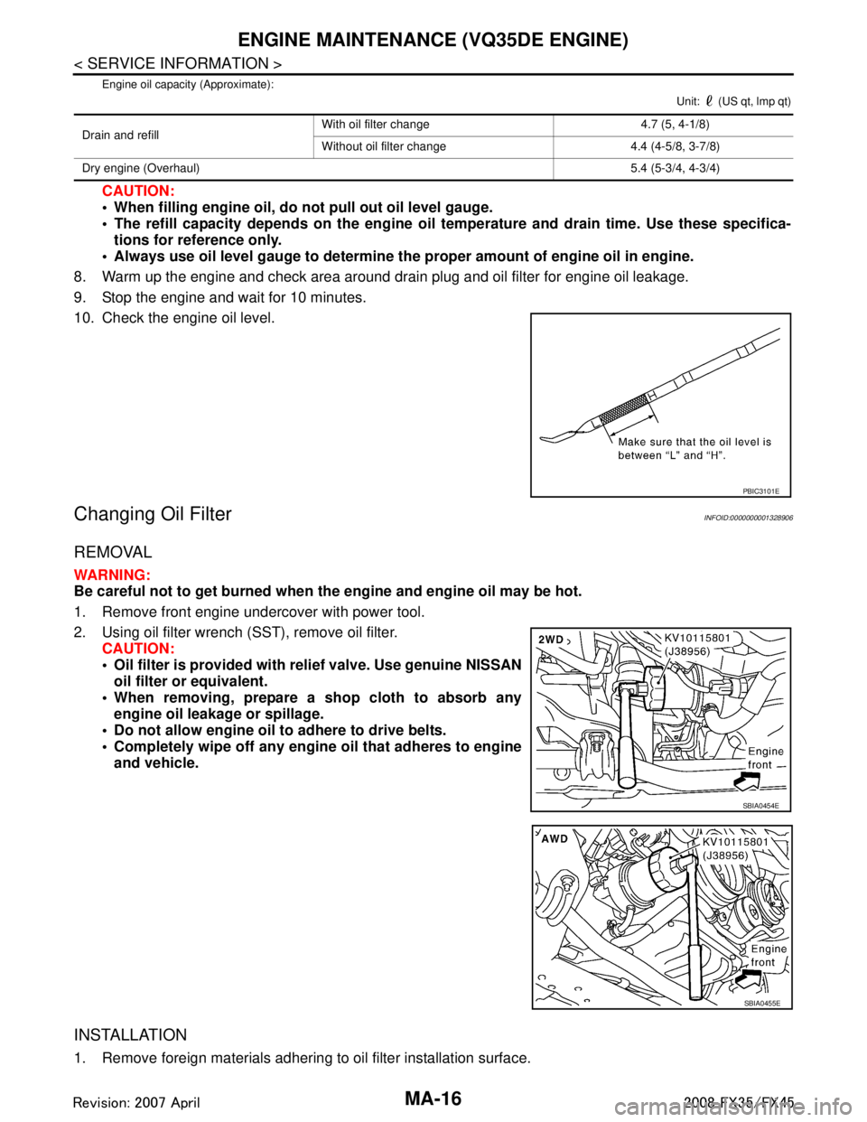
10. Check the engine oil level.
Changing Oil FilterINFOID:0000000001328906
REMOVAL
WARNING:
Be careful not to get burned when the engine and engine oil may be hot.
1. Remove front engine undercover with power tool.
2. Using oil filter wrench (SST), remove oil filter. CAUTION:
Oil filter is provided with relief valve. Use genuine NISSAN
oil filter or equivalent.
When removing, prepare a sh op cloth to absorb any
engine oil leakage or spillage.
Do not allow engine oil to adhere to drive belts.
Completely wipe off any engine oil that adheres to engine and vehicle.
INSTALLATION
1. Remove foreign materials adhering to oil filter installation surface.
Drain and refill With oil filter change 4.7 (5, 4-1/8)
Without oil filter change 4.4 (4-5/8, 3-7/8)
Dry engine (Overhaul) 5.4 (5-3/4, 4-3/4)
PBIC3101E
SBIA0454E
SBIA0455E
3AA93ABC3ACD3AC03ACA3AC03AC63AC53A913A773A893A873A873A8E3A773A983AC73AC93AC03AC3
3A893A873A873A8F3A773A9D3AAF3A8A3A8C3A863A9D3AAF3A8B3A8C
Page 3340 of 3924

ENGINE MAINTENANCE (VK45DE ENGINE)MA-23
< SERVICE INFORMATION >
C
DE
F
G H
I
J
K
M A
B
MA
N
O P
The refill capacity depends on the engine oi l temperature and drain time. Use these specifica-
tions for reference only.
Always use oil level gauge to determine the pr oper amount of engine oil in the engine.
8. Warm up engine and check area around drain plug and oil filter for oil leakage.
9. Stop engine and wait for 15 minutes.
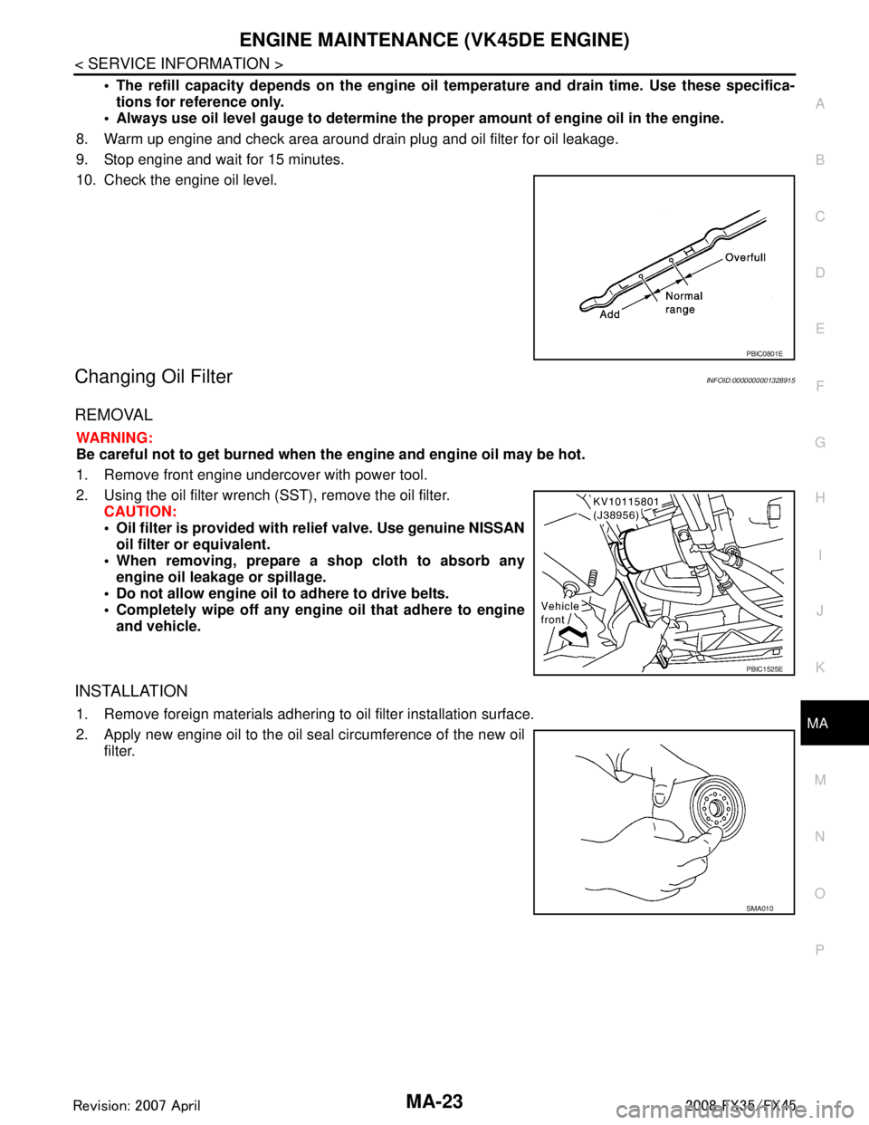
10. Check the engine oil level.
Changing Oil FilterINFOID:0000000001328915
REMOVAL
WARNING:
Be careful not to get burned when th e engine and engine oil may be hot.
1. Remove front engine undercover with power tool.
2. Using the oil filter wrench (SST), remove the oil filter. CAUTION:
Oil filter is provided with relief valve. Use genuine NISSAN
oil filter or equivalent.
When removing, prepare a s hop cloth to absorb any
engine oil leakage or spillage.
Do not allow engine oil to adhere to drive belts.
Completely wipe off any engine oil that adhere to engine
and vehicle.
INSTALLATION
1. Remove foreign materials adhering to oil filter installation surface.
2. Apply new engine oil to the oil seal circumference of the new oil filter.
PBIC0801E
PBIC1525E
SMA010
3AA93ABC3ACD3AC03ACA3AC03AC63AC53A913A773A893A873A873A8E3A773A983AC73AC93AC03AC3
3A893A873A873A8F3A773A9D3AAF3A8A3A8C3A863A9D3AAF3A8B3A8C
Page 3351 of 3924

MA-34
< SERVICE INFORMATION >
CHASSIS AND BODY MAINTENANCE
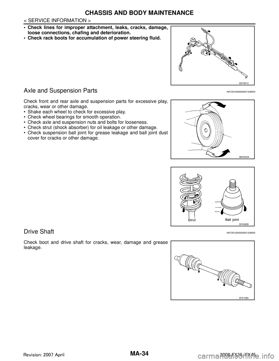
Check lines for improper attachment, leaks, cracks, damage,loose connections, chaf ing and deterioration.
Check rack boots for accumulati on of power steering fluid.
Axle and Suspension PartsINFOID:0000000001328934
Check front and rear axle and suspension parts for excessive play,
cracks, wear or other damage.
Shake each wheel to check for excessive play.
Check wheel bearings for smooth operation.
Check axle and suspension nuts and bolts for looseness.
Check strut (shock absorber) for oil leakage or other damage.
Check suspension ball joint for grease leakage and ball joint dust
cover for cracks or other damage.
Drive ShaftINFOID:0000000001328935
Check boot and drive shaft for cracks, wear, damage and grease
leakage.
SST851C
SMA525A
SFA392B
SFA108A
3AA93ABC3ACD3AC03ACA3AC03AC63AC53A913A773A893A873A873A8E3A773A983AC73AC93AC03AC3
3A893A873A873A8F3A773A9D3AAF3A8A3A8C3A863A9D3AAF3A8B3A8C