2008 INFINITI FX35 ABS
[x] Cancel search: ABSPage 3591 of 3924
RSU-10
< SERVICE INFORMATION >
SHOCK ABSORBER
Check bound bumper and bushing for cracks, deformation or other damage. Replace if necessary.
ASSEMBLY
Refer to RSU-6, "Removal and Installation" for tightening torque. Assembly in the reverse order of disas-
sembly.
NOTE:
Refer to component parts location and do not reuse non-reusable parts.
Make sure piston rod on shock absorber is not damaged when attaching components to shock absorber.
3AA93ABC3ACD3AC03ACA3AC03AC63AC53A913A773A893A873A873A8E3A773A983AC73AC93AC03AC3
3A893A873A873A8F3A773A9D3AAF3A8A3A8C3A863A9D3AAF3A8B3A8C
Page 3595 of 3924
RSU-14
< SERVICE INFORMATION >
FRONT LOWER LINK
FRONT LOWER LINK
Removal and InstallationINFOID:0000000001327559
REMOVAL
1. Remove tires from vehicle with power tool.
2. Set jack under rear lower link.
3. Remove front lower link protector.
4. Remove shock absorber assembly from vehicle. Refer to RSU-9, "
Removal and Installation".
5. Remove fixing nut and bolt between front lower link and axle with power tool.
6. Remove fixing nut and bolt between front lower li nk and rear suspension member with power tool.
7. Remove front lower link from vehicle.
INSPECTION AFTER REMOVAL
Check front lower link and bushing for any deforma tion, crack, or damage. Replace if necessary.
INSTALLATION
Refer to RSU-6, "Removal and Installation" for tightening torque. Install in the reverse order of removal.
NOTE:
Refer to component parts location and do not reuse non-reusable parts.
Perform final tightening of rear suspension member and axle installation position (rubber bushing) under
unladen conditions with tires on level ground. Check wheel alignment. Refer to RSU-5, "
Wheel AlignmentIn-
spection".
After adjusting wheel alignment, adjust neutral position of steering angle sensor. Refer to BRC-8, "
Adjust-
ment of Steering Angle Sensor Neutral Position".
3AA93ABC3ACD3AC03ACA3AC03AC63AC53A913A773A893A873A873A8E3A773A983AC73AC93AC03AC3
3A893A873A873A8F3A773A9D3AAF3A8A3A8C3A863A9D3AAF3A8B3A8C
Page 3596 of 3924
REAR LOWER LINK & COIL SPRINGRSU-15
< SERVICE INFORMATION >
C
DF
G H
I
J
K L
M A
B
RSU
N
O P
REAR LOWER LINK & COIL SPRING
Removal and InstallationINFOID:0000000001327560
REMOVAL
1. Remove tire with power tool.
2. Set jack under rear lower link.
3. Loosen fixing bolt and nut between rear lower link and suspension member, and then remove fixing bolt and nut between rear axle and rear lower link with power tool.
4. Slowly lower jack, then remove upper seat, co il spring and rubber seat from rear lower link.
5. Remove fixing bolt and nut between rear suspensi on member and rear lower link with power tool.
INSPECTION AFTER REMOVAL
Check rear lower link, bushing and coil spring for deformation, cracks, and damage. Replace rear lower link
and coil spring if necessary.
INSTALLATION
Refer to RSU-6, "Removal and Installation"for tightening torque. Install in the reverse order of removal.
CAUTION:
Refer to component parts location an d do not reuse non-reusable parts.
Make sure upper seat is attached as shown in the figure.
NOTE:
Insert bracket tabs (3) and the inside protrusion on upper seat into
each other beforehand as shown in the figure.
Match up rubber seat indentions and rear lower link grooves and
attach.
NOTE:
Make sure spring is not upside down. The top and bottom are indi-
cated by paint color.
Perform final tightening of rear suspension mem ber and axle installation position (rubber bushing) under
unladen conditions with tires on level ground. Check wheel alignment. Refer to RSU-18, "
Wheel Alignment
(Unladen*)".
SEIA0229E
3AA93ABC3ACD3AC03ACA3AC03AC63AC53A913A773A893A873A873A8E3A773A983AC73AC93AC03AC3
3A893A873A873A8F3A773A9D3AAF3A8A3A8C3A863A9D3AAF3A8B3A8C
Page 3598 of 3924
REAR SUSPENSION MEMBERRSU-17
< SERVICE INFORMATION >
C
DF
G H
I
J
K L
M A
B
RSU
N
O P
REAR SUSPENSION MEMBER
Removal and InstallationINFOID:0000000001327562
REMOVAL
1. Remove tires from vehicle with power tool.
2. Remove brake caliper with power tool. Hang it in a place where it will not interfere with work. Refer to BR-
24.
NOTE:
Avoid depressing brake pedal while brake caliper is removed.
3. Remove wheel sensor from rear final drive, t hen remove wheel sensor harness from rear suspension
member. Refer to BRC-52
.
4. Remove height sensor harness from rear suspension member (if equipped).
5. Remove center muffler and main muffler. Refer to EX-3
.
6. Remove stabilizer bar. Refer to RSU-16, "
Removal and Installation".
7. Remove rear drive shaft. Refer to RAX-10
.
8. Remove propeller shaft. Refer to PR-7
.
9. Remove rear final drive. Refer to RFD-16, "
Removal and Installation".
10. Separate attachments between parking brake cable and vehicle and rear suspension member. Refer to PB-4
.
11. Remove rear lower link and coil spring. Refer to RSU-14, "
Removal and Installation".
12. Remove fixing bolt in lower side of shock absorber with power tool.
13. Set jack under rear suspension member.
14. Remove fixing bolts and nuts of tunnel stay and member stay with power tool, then remove those parts from vehicle and rear suspension member.
15. Remove fixing bolts and nuts of rear pin stay with pow er tool and then remove rear pin stay from vehicle
and rear suspension member.
16. Slowly lowering jack, then remove rear suspension me mber, suspension arm, radius rod, front lower link
and axle from vehicle as a unit.
17. Remove fixing bolts and nuts with power tool, then re move suspension arm, front lower link, and radius
rod from rear suspension member.
INSPECTION AFTER REMOVAL
Check rear suspension member for deformation, cracks, and other damage and replace if necessary.
INSTALLATION
Refer to RSU-6, "Removal and Installation", for tightening torque. Install in the reverse order of removal.
NOTE:
Refer to component parts location and do not reuse non-reusable parts.
Perform final tightening of installation position of links (rubber bushing) under unladen conditions with tires
on level ground. Check wheel alignment. Refer to RSU-5, "
Wheel AlignmentInspection".
After adjusting wheel alignment, adjust neutral position of steering angle sensor. Refer to BRC-8, "
Adjust-
ment of Steering Angle Sensor Neutral Position".
3AA93ABC3ACD3AC03ACA3AC03AC63AC53A913A773A893A873A873A8E3A773A983AC73AC93AC03AC3
3A893A873A873A8F3A773A9D3AAF3A8A3A8C3A863A9D3AAF3A8B3A8C
Page 3730 of 3924
FRONT SEATSE-91
< SERVICE INFORMATION >
C
DE
F
G H
J
K L
M A
B
SE
N
O P
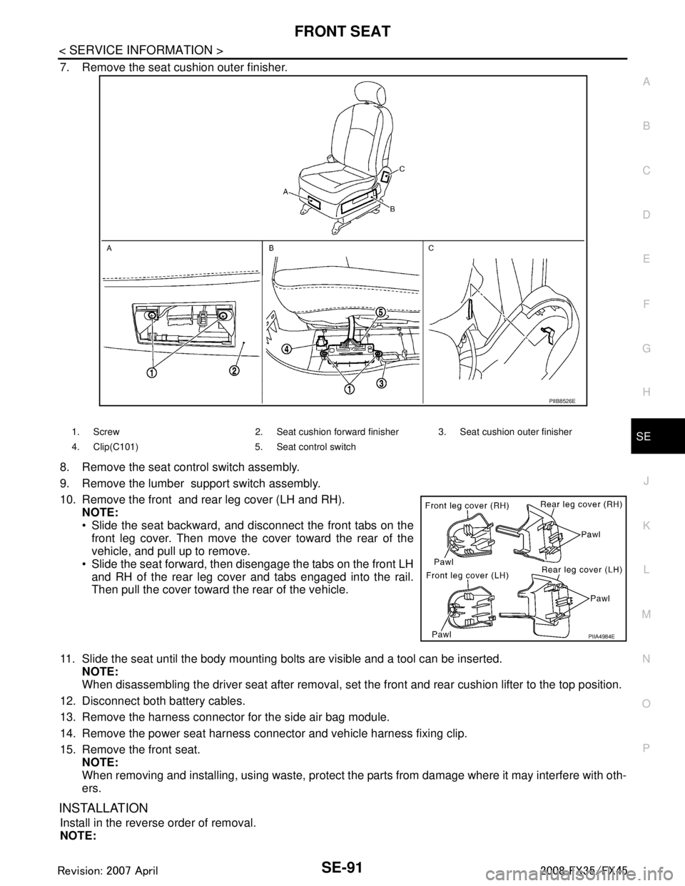
7. Remove the seat cushion outer finisher.
8. Remove the seat control switch assembly.
9. Remove the lumber support switch assembly.
10. Remove the front and rear leg cover (LH and RH). NOTE:
Slide the seat backward, and disconnect the front tabs on the
front leg cover. Then move the cover toward the rear of the
vehicle, and pull up to remove.
Slide the seat forward, then disengage the tabs on the front LH and RH of the rear leg cover and tabs engaged into the rail.
Then pull the cover toward the rear of the vehicle.
11. Slide the seat until the body mounting bolts are visible and a tool can be inserted. NOTE:
When disassembling the driver seat after removal, set the front and rear cushion lifter to the top position.
12. Disconnect both battery cables.
13. Remove the harness connector for the side air bag module.
14. Remove the power seat harness connector and vehicle harness fixing clip.
15. Remove the front seat. NOTE:
When removing and installing, using waste, protect t he parts from damage where it may interfere with oth-
ers.
INSTALLATION
Install in the reverse order of removal.
NOTE:
PIIB8526E
1. Screw 2. Seat cushion forward finisher 3. Seat cushion outer finisher
4. Clip(C101) 5. Seat control switch
PIIA4984E
3AA93ABC3ACD3AC03ACA3AC03AC63AC53A913A773A893A873A873A8E3A773A983AC73AC93AC03AC3
3A893A873A873A8F3A773A9D3AAF3A8A3A8C3A863A9D3AAF3A8B3A8C
Page 3736 of 3924
REAR SEATSE-97
< SERVICE INFORMATION >
C
DE
F
G H
J
K L
M A
B
SE
N
O P
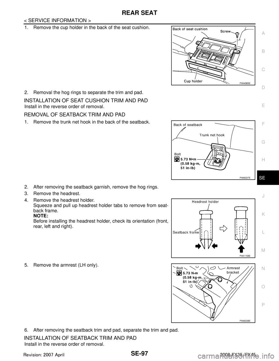
1. Remove the cup holder in the back of the seat cushion.
2. Removal the hog rings to separate the trim and pad.
INSTALLATION OF SEAT CUSHION TRIM AND PAD
Install in the reverse order of removal.
R E M O VA L O F S E AT B A C K T R I M A N D PA D
1. Remove the trunk net hook in the back of the seatback.
2. After removing the seatback garnish, remove the hog rings.
3. Remove the headrest.
4. Remove the headrest holder. Squeeze and pull up headrest holder tabs to remove from seat-
back frame.
NOTE:
Before installing the headrest holder, check its orientation (front,
rear, left and right).
5. Remove the armrest (LH only).
6. After removing the seatback trim and pad, separate the trim and pad.
INSTALLATION OF SEATBACK TRIM AND PAD
Install in the reverse order of removal.
PIIA4985E
PIIA6037E
PIIA1158E
PIIA6038E
3AA93ABC3ACD3AC03ACA3AC03AC63AC53A913A773A893A873A873A8E3A773A983AC73AC93AC03AC3
3A893A873A873A8F3A773A9D3AAF3A8A3A8C3A863A9D3AAF3A8B3A8C
Page 3787 of 3924
TF-1
DRIVELINE/AXLE
CEF
G H
I
J
K L
M
SECTION TF
A
B
TF
N
O P
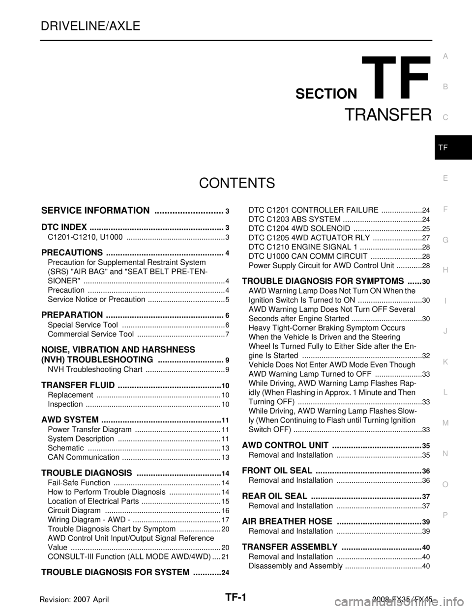
CONTENTS
TRANSFER
SERVICE INFORMATION .. ..........................3
DTC INDEX ..................................................... .....3
C1201-C1210, U1000 ......................................... ......3
PRECAUTIONS ...................................................4
Precaution for Supplemental Restraint System
(SRS) "AIR BAG" and "SEAT BELT PRE-TEN-
SIONER" ............................................................. ......
4
Precaution .................................................................4
Service Notice or Precaution .....................................5
PREPARATION ...................................................6
Special Service Tool ........................................... ......6
Commercial Service Tool ..........................................7
NOISE, VIBRATION AND HARSHNESS
(NVH) TROUBLESHOOTING .............................
9
NVH Troubleshooting Chart ................................ ......9
TRANSFER FLUID .............................................10
Replacement ....................................................... ....10
Inspection ................................................................10
AWD SYSTEM ................................................ ....11
Power Transfer Diagram ..................................... ....11
System Description .................................................11
Schematic ...............................................................13
CAN Communication ...............................................13
TROUBLE DIAGNOSIS .....................................14
Fail-Safe Function ............................................... ....14
How to Perform Trouble Diagnosis .........................14
Location of Electrical Parts ......................................15
Circuit Diagram .......................................................16
Wiring Diagram - AWD - ..........................................17
Trouble Diagnosis Chart by Symptom ....................20
AWD Control Unit Input/Output Signal Reference
Value ................................................................... ....
20
CONSULT-III Function (ALL MODE AWD/4WD) ....21
TROUBLE DIAGNOSIS FOR SYSTEM .............24
DTC C1201 CONTROLLER FAILURE ................ ....24
DTC C1203 ABS SYSTEM ......................................24
DTC C1204 4WD SOLENOID ............................. ....25
DTC C1205 4WD ACTUATOR RLY ........................27
DTC C1210 ENGINE SIGNAL 1 ..............................28
DTC U1000 CAN COMM CIRCUIT .........................28
Power Supply Circuit for AWD Control Unit .............28
TROUBLE DIAGNOSIS FOR SYMPTOMS ......30
AWD Warning Lamp Does Not Turn ON When the
Ignition Switch Is Turned to ON ...............................
30
AWD Warning Lamp Does Not Turn OFF Several
Seconds after Engine Started ..................................
30
Heavy Tight-Corner Braking Symptom Occurs
When the Vehicle Is Driven and the Steering
Wheel Is Turned Fully to Either Side after the En-
gine Is Started .........................................................
32
Vehicle Does Not Enter AWD Mode Even Though
AWD Warning Lamp Turned to OFF .......................
33
While Driving, AWD Warning Lamp Flashes Rap-
idly (When Flashing in Approx. 1 Minute and Then
Turning OFF) ....................................................... ....
33
While Driving, AWD Warning Lamp Flashes Slow-
ly (When Continuing to Flash until Turning Ignition
Switch OFF) .............................................................
33
AWD CONTROL UNIT ......................................35
Removal and Installation .........................................35
FRONT OIL SEAL .............................................36
Removal and Installation .........................................36
REAR OIL SEAL ...............................................37
Removal and Installation .........................................37
AIR BREATHER HOSE ....................................39
Removal and Installation .........................................39
TRANSFER ASSEMBLY ..................................40
Removal and Installation .........................................40
Disassembly and Assembly .....................................40
3AA93ABC3ACD3AC03ACA3AC03AC63AC53A913A773A893A873A873A8E3A773A983AC73AC93AC03AC3
3A893A873A873A8F3A773A9D3AAF3A8A3A8C3A863A9D3AAF3A8B3A8C
Page 3789 of 3924
DTC INDEXTF-3
< SERVICE INFORMATION >
CEF
G H
I
J
K L
M A
B
TF
N
O P
SERVICE INFORMATION
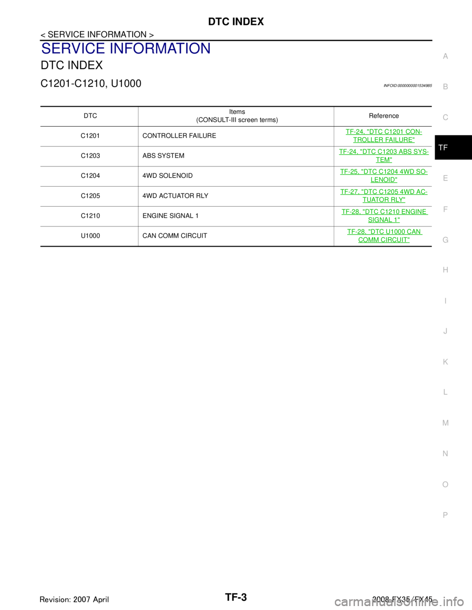
DTC INDEX
C1201-C1210, U1000INFOID:0000000001534985
DTC Items
(CONSULT-III screen terms) Reference
C1201 CONTROLLER FAILURE TF-24, "
DTC C1201 CON-
TROLLER FAILURE"
C1203 ABS SYSTEMTF-24, "DTC C1203 ABS SYS-
TEM"
C1204 4WD SOLENOID TF-25, "DTC C1204 4WD SO-
LENOID"
C1205 4WD ACTUATOR RLY TF-27, "DTC C1205 4WD AC-
TUATOR RLY"
C1210 ENGINE SIGNAL 1
TF-28, "DTC C1210 ENGINE
SIGNAL 1"
U1000 CAN COMM CIRCUIT TF-28, "DTC U1000 CAN
COMM CIRCUIT"
3AA93ABC3ACD3AC03ACA3AC03AC63AC53A913A773A893A873A873A8E3A773A983AC73AC93AC03AC3
3A893A873A873A8F3A773A9D3AAF3A8A3A8C3A863A9D3AAF3A8B3A8C