Page 3799 of 3924

AWD SYSTEMTF-13
< SERVICE INFORMATION >
CEF
G H
I
J
K L
M A
B
TF
N
O P
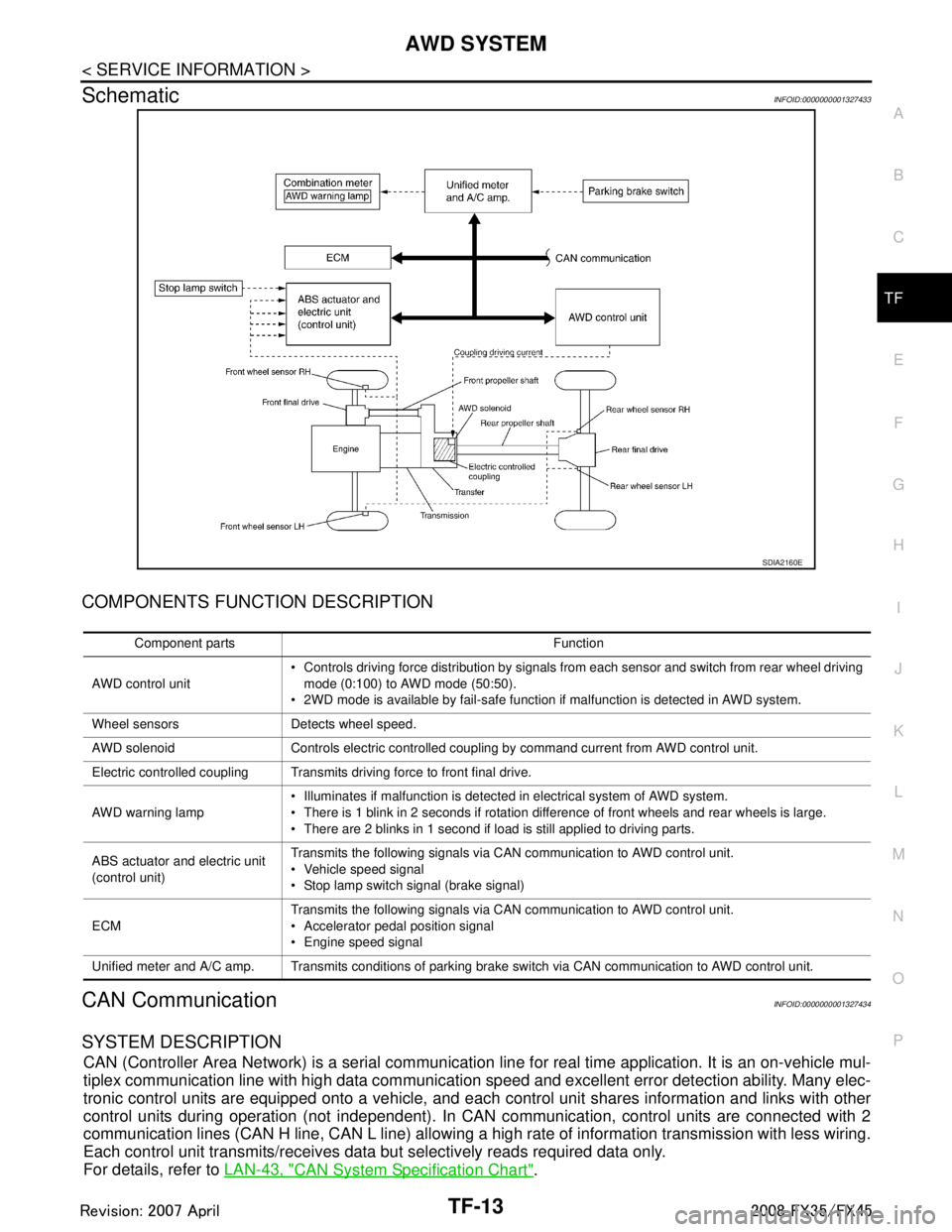
SchematicINFOID:0000000001327433
COMPONENTS FUNCTION DESCRIPTION
CAN CommunicationINFOID:0000000001327434
SYSTEM DESCRIPTION
CAN (Controller Area Network) is a serial communication li ne for real time application. It is an on-vehicle mul-
tiplex communication line with high data communication speed and excellent error detection ability. Many elec-
tronic control units are equipped onto a vehicle, and each control unit shares information and links with other
control units during operation (not independent). In CAN communication, control units are connected with 2
communication lines (CAN H line, CAN L line) allowing a high rate of information transmission with less wiring.
Each control unit transmits/receives data but selectively reads required data only.
For details, refer to LAN-43, "
CAN System Specification Chart".
SDIA2160E
Component parts Function
AWD control unit Controls driving force distribution by signals from each sensor and switch from rear wheel driving
mode (0:100) to AWD mode (50:50).
2WD mode is available by fail-safe function if malfunction is detected in AWD system.
Wheel sensors Detects wheel speed.
AWD solenoid Controls electric controlled coupling by command current from AWD control unit.
Electric controlled coupling Transmits driving force to front final drive.
AWD warning lamp Illuminates if malfunction is detected in electrical system of AWD system.
There is 1 blink in 2 seconds if rotation difference of front wheels and rear wheels is large.
There are 2 blinks in 1 second if load is still applied to driving parts.
ABS actuator and electric unit
(control unit) Transmits the following signals via CAN communication to AWD control unit.
Vehicle speed signal
Stop lamp switch signal (brake signal)
ECM Transmits the following signals via CAN communication to AWD control unit.
Accelerator pedal position signal
Engine speed signal
Unified meter and A/C amp. Transmits conditions of parking brake switch via CAN communication to AWD control unit.
3AA93ABC3ACD3AC03ACA3AC03AC63AC53A913A773A893A873A873A8E3A773A983AC73AC93AC03AC3
3A893A873A873A8F3A773A9D3AAF3A8A3A8C3A863A9D3AAF3A8B3A8C
Page 3808 of 3924

TF-22
< SERVICE INFORMATION >
TROUBLE DIAGNOSIS
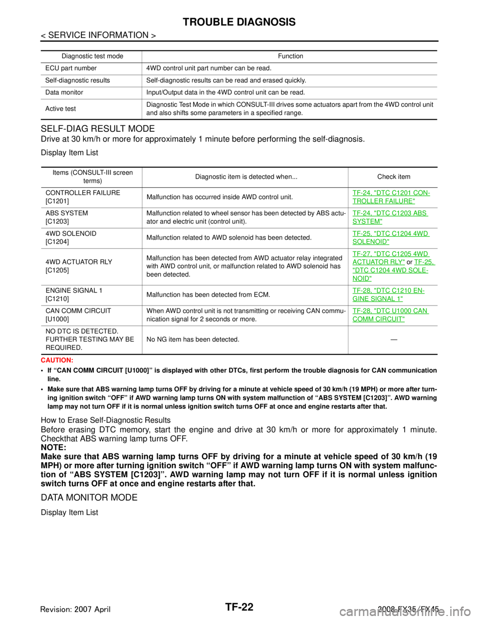
SELF-DIAG RESULT MODE
Drive at 30 km/h or more for approximately 1 minute before performing the self-diagnosis.
Display Item List
CAUTION:
If “CAN COMM CIRCUIT [U1000]” is displayed with other DTCs, first perform the trouble diagnosis for CAN communication
line.
Make sure that ABS warning lamp turns OFF by driving for a minute at vehicle speed of 30 km/h (19 MPH) or more after turn- ing ignition switch “OFF” if AWD warning lamp turns ON with system malfunction of “ABS SYSTEM [C1203]”. AWD warning
lamp may not turn OFF if it is normal unless ignition switch turns OFF at once and engine restarts after that.
How to Erase Self-Diagnostic Results
Before erasing DTC memory, start the engine and drive at 30 km/h or more for approximately 1 minute.
Checkthat ABS warning lamp turns OFF.
NOTE:
Make sure that ABS warning lamp turns OFF by driv ing for a minute at vehicle speed of 30 km/h (19
MPH) or more after turning ignition switch “OFF ” if AWD warning lamp turns ON with system malfunc-
tion of “ABS SYSTE M [C1203]”. AWD warning lamp may not turn OFF if it is normal unless ignition
switch turns OFF at once and engine restarts after that.
DATA MONITOR MODE
Display Item List
Diagnostic test mode Function
ECU part number 4WD control unit part number can be read.
Self-diagnostic results Self-diagnostic results can be read and erased quickly.
Data monitor Input/Output data in the 4WD control unit can be read.
Active test Diagnostic Test Mode in which CONSULT-III drives some actuators apart from the 4WD control unit
and also shifts some parameters in a specified range.
Items (CONSULT-III screen
terms) Diagnostic item is detected when... Check item
CONTROLLER FAILURE
[C1201] Malfunction has occurred inside AWD control unit. TF-24, "
DTC C1201 CON-
TROLLER FAILURE"
ABS SYSTEM
[C1203]Malfunction related to wheel sensor
has been detected by ABS actu-
ator and electric unit (control unit). TF-24, "DTC C1203 ABS
SYSTEM"
4WD SOLENOID
[C1204]
Malfunction related to AWD solenoid has been detected.
TF-25, "DTC C1204 4WD
SOLENOID"
4WD ACTUATOR RLY
[C1205]Malfunction has been detected from AWD actuator relay integrated
with AWD control unit, or malfunction related to AWD solenoid has
been detected. TF-27, "
DTC C1205 4WD
ACTUATOR RLY" or
TF-25,
"DTC C1204 4WD SOLE-
NOID"
ENGINE SIGNAL 1
[C1210] Malfunction has been detected from ECM. TF-28, "DTC C1210 EN-
GINE SIGNAL 1"
CAN COMM CIRCUIT
[U1000]When AWD control unit is not transmitting or receiving CAN commu-
nication signal for 2 seconds or more. TF-28, "DTC U1000 CAN
COMM CIRCUIT"
NO DTC IS DETECTED.
FURTHER TESTING MAY BE
REQUIRED.
No NG item has been detected. —
3AA93ABC3ACD3AC03ACA3AC03AC63AC53A913A773A893A873A873A8E3A773A983AC73AC93AC03AC3
3A893A873A873A8F3A773A9D3AAF3A8A3A8C3A863A9D3AAF3A8B3A8C
Page 3810 of 3924

TF-24
< SERVICE INFORMATION >
TROUBLE DIAGNOSIS FOR SYSTEM
TROUBLE DIAGNOSIS FOR SYSTEM
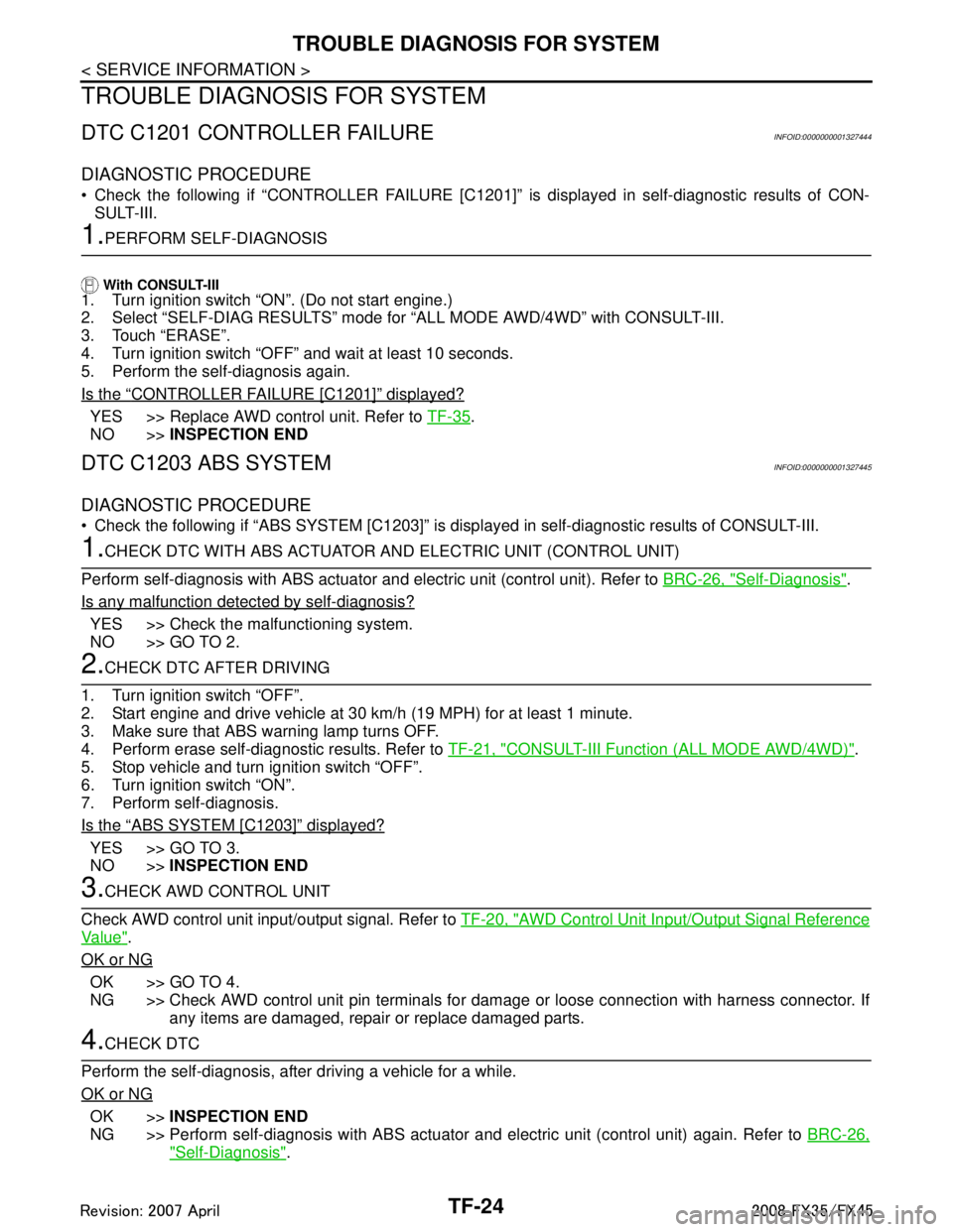
DTC C1201 CONTROLLER FAILUREINFOID:0000000001327444
DIAGNOSTIC PROCEDURE
Check the following if “CONTROLLER FAILURE [C1201]” is displayed in self-diagnostic results of CON-SULT-III.
1.PERFORM SELF-DIAGNOSIS
With CONSULT-III1. Turn ignition switch “ON”. (Do not start engine.)
2. Select “SELF-DIAG RESULTS” mode fo r “ALL MODE AWD/4WD” with CONSULT-III.
3. Touch “ERASE”.
4. Turn ignition switch “OFF” and wait at least 10 seconds.
5. Perform the self-diagnosis again.
Is the
“CONTROLLER FAILURE [C1201]” displayed?
YES >> Replace AWD control unit. Refer to TF-35.
NO >> INSPECTION END
DTC C1203 ABS SYSTEMINFOID:0000000001327445
DIAGNOSTIC PROCEDURE
Check the following if “ABS SYSTEM [C1203]” is disp layed in self-diagnostic results of CONSULT-III.
1.CHECK DTC WITH ABS ACTUATOR AND ELECTRIC UNIT (CONTROL UNIT)
Perform self-diagnosis with ABS actuator and electric unit (control unit). Refer to BRC-26, "
Self-Diagnosis".
Is any malfunction detec ted by self-diagnosis?
YES >> Check the malfunctioning system.
NO >> GO TO 2.
2.CHECK DTC AFTER DRIVING
1. Turn ignition switch “OFF”.
2. Start engine and drive vehicle at 30 km/h (19 MPH) for at least 1 minute.
3. Make sure that ABS warning lamp turns OFF.
4. Perform erase self-diagnostic results. Refer to TF-21, "
CONSULT-III Function (ALL MODE AWD/4WD)".
5. Stop vehicle and turn ignition switch “OFF”.
6. Turn ignition switch “ON”.
7. Perform self-diagnosis.
Is the
“ABS SYSTEM [C1203]” displayed?
YES >> GO TO 3.
NO >> INSPECTION END
3.CHECK AWD CONTROL UNIT
Check AWD control unit input/output signal. Refer to TF-20, "
AWD Control Unit Input/Output Signal Reference
Va l u e".
OK or NG
OK >> GO TO 4.
NG >> Check AWD control unit pin terminals for dam age or loose connection with harness connector. If
any items are damaged, repair or replace damaged parts.
4.CHECK DTC
Perform the self-diagnosis, after driving a vehicle for a while.
OK or NG
OK >> INSPECTION END
NG >> Perform self-diagnosis with ABS actuator and electric unit (control unit) again. Refer to BRC-26,
"Self-Diagnosis".
3AA93ABC3ACD3AC03ACA3AC03AC63AC53A913A773A893A873A873A8E3A773A983AC73AC93AC03AC3
3A893A873A873A8F3A773A9D3AAF3A8A3A8C3A863A9D3AAF3A8B3A8C