2008 INFINITI FX35 seat adjustment
[x] Cancel search: seat adjustmentPage 2440 of 3924
PRECAUTIONSEI-3
< SERVICE INFORMATION >
C
DE
F
G H
J
K L
M A
B
EI
N
O P
SERVICE INFORMATION
PRECAUTIONS
Precaution for Supplemental Restraint System (SRS) "AIR BAG" and "SEAT BELT
PRE-TENSIONER"
INFOID:0000000001612896
The Supplemental Restraint System such as “A IR BAG” and “SEAT BELT PRE-TENSIONER”, used along
with a front seat belt, helps to reduce the risk or severi ty of injury to the driver and front passenger for certain
types of collision. This system includes seat belt switch inputs and dual stage front air bag modules. The SRS
system uses the seat belt switches to determine the front air bag deployment, and may only deploy one front
air bag, depending on the severity of a collision and whether the front occupants are belted or unbelted.
Information necessary to service the system safely is included in the “SUPPLEMENTAL RESTRAINT SYS-
TEM” and “SEAT BELTS” of this Service Manual.
WARNING:
• To avoid rendering the SRS inoper ative, which could increase the risk of personal injury or death in
the event of a collision which would result in air bag inflation, all maintenance must be performed by
an authorized NISSAN/INFINITI dealer.
Improper maintenance, including in correct removal and installation of the SRS, can lead to personal
injury caused by unintentional act ivation of the system. For removal of Spiral Cable and Air Bag
Module, see the “SUPPLEMEN TAL RESTRAINT SYSTEM”.
Do not use electrical test equipm ent on any circuit related to the SRS unless instructed to in this
Service Manual. SRS wiring harnesses can be identi fied by yellow and/or orange harnesses or har-
ness connectors.
Precaution for Procedur e without Cowl Top CoverINFOID:0000000001612888
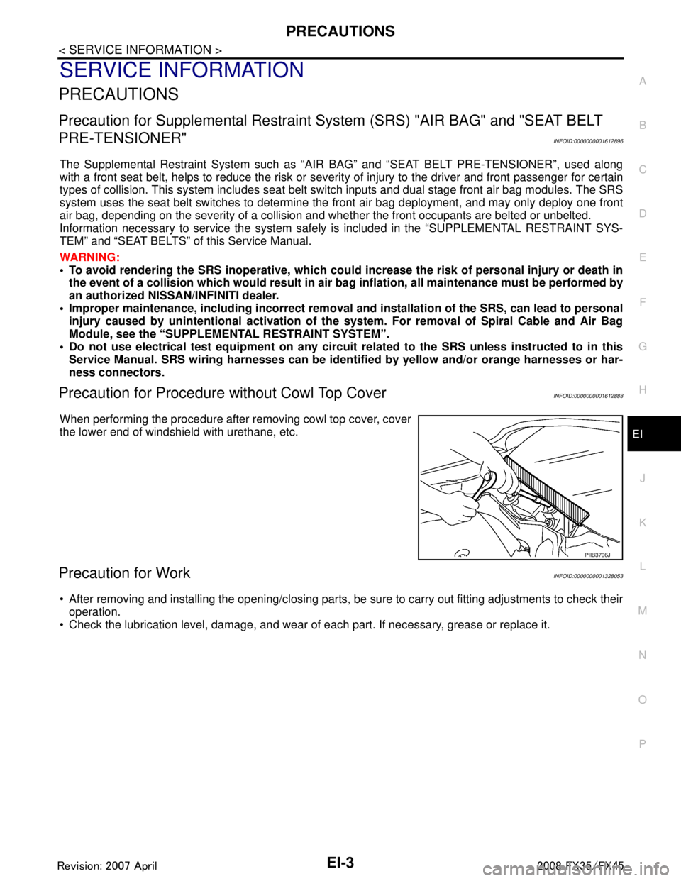
When performing the procedure after removing cowl top cover, cover
the lower end of windshield with urethane, etc.
Precaution for WorkINFOID:0000000001328053
After removing and installing the opening/closing parts, be sure to carry out fitting adjustments to check their
operation.
Check the lubrication level, damage, and wear of each part. If necessary, grease or replace it.
PIIB3706J
3AA93ABC3ACD3AC03ACA3AC03AC63AC53A913A773A893A873A873A8E3A773A983AC73AC93AC03AC3
3A893A873A873A8F3A773A9D3AAF3A8A3A8C3A863A9D3AAF3A8B3A8C
Page 2445 of 3924

EI-8
< SERVICE INFORMATION >
SQUEAK AND RATTLE TROUBLE DIAGNOSES
Most of these incidents can be repaired by adjusting, securing or insulating the item(s) or component(s) caus-
ing the noise.
SUNROOF/HEADLINING
Noises in the sunroof/headlining area c an often be traced to one of the following:
1. Sunroof lid, rail, linkage or seals making a rattle or light knocking noise
2. Sun-visor shaft shaking in the holder
3. Front or rear windshield touching headlining and squeaking
Again, pressing on the components to stop the noise while duplicating the conditions can isolate most of these
incidents. Repairs usually consist of insulating with felt cloth tape.
SEATS
When isolating seat noise it's important to note the pos ition the seat is in and the load placed on the seat when
the noise is present. These conditions should be dupl icated when verifying and isolating the cause of the
noise.
Cause of seat noise include:
1. Headrest rods and holder
2. A squeak between the seat pad cushion and frame
3. The rear seatback lock and bracket
These noises can be isolated by moving or pressing on the suspected components while duplicating the con-
ditions under which the noise occurs. Most of thes e incidents can be repaired by repositioning the component
or applying urethane tape to the contact area.
UNDERHOOD
Some interior noise may be caused by components under the hood or on the engine wall. The noise is then
transmitted into the passenger compartment.
Causes of transmitted under-hood noise include:
1. Any component mounted to the engine wall
2. Components that pass through the engine wall
3. Engine wall mounts and connectors
4. Loose radiator mounting pins
5. Hood bumpers out of adjustment
6. Hood striker out of adjustment
These noises can be difficult to isolate since they cannot be reached from the interior of the vehicle. The best
method is to secure, move or insulate one component at a time and test drive the \
vehicle. Also, engine RPM
or load can be changed to isolate the noise. Repairs can usually be made by moving, adjusting, securing, or
insulating the component causing the noise.
3AA93ABC3ACD3AC03ACA3AC03AC63AC53A913A773A893A873A873A8E3A773A983AC73AC93AC03AC3
3A893A873A873A8F3A773A9D3AAF3A8A3A8C3A863A9D3AAF3A8B3A8C
Page 2801 of 3924
FFD-10
< SERVICE INFORMATION >
FRONT OIL SEAL
INSTALLATION
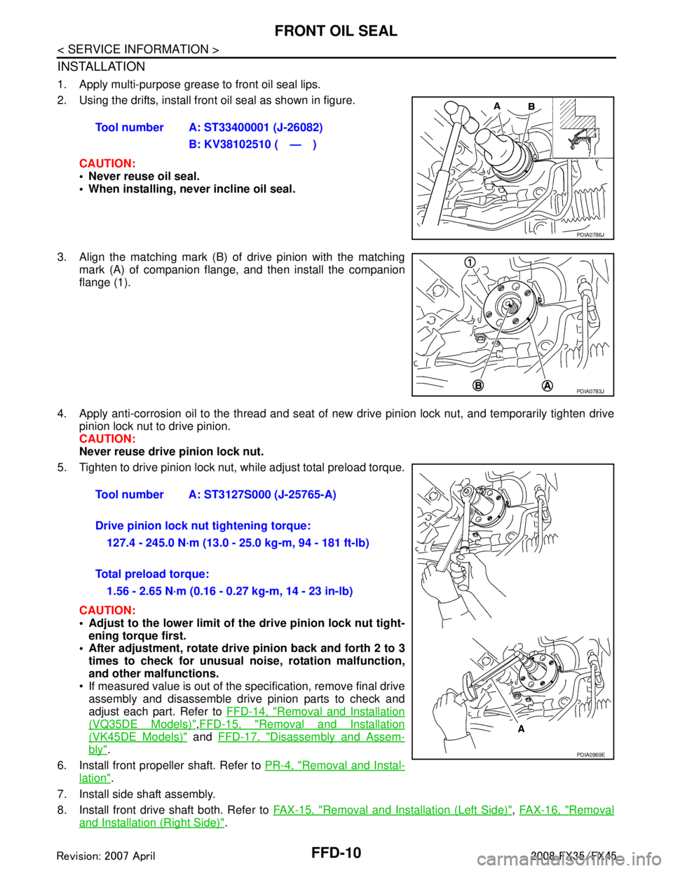
1. Apply multi-purpose grease to front oil seal lips.
2. Using the drifts, install front oil seal as shown in figure.CAUTION:
• Never reuse oil seal.
When installing, n ever incline oil seal.
3. Align the matching mark (B) of drive pinion with the matching mark (A) of companion flange, and then install the companion
flange (1).
4. Apply anti-corrosion oil to the thread and seat of new drive pinion lock nut, and temporarily tighten drive
pinion lock nut to drive pinion.
CAUTION:
Never reuse drive pinion lock nut.
5. Tighten to drive pinion lock nut, while adjust total preload torque.
CAUTION:
Adjust to the lower limit of the drive pinion lock nut tight-
ening torque first.
After adjustment, rotate dri ve pinion back and forth 2 to 3
times to check for unusual no ise, rotation malfunction,
and other malfunctions.
If measured value is out of the specification, remove final drive assembly and disassemble drive pinion parts to check and
adjust each part. Refer to FFD-14, "
Removal and Installation
(VQ35DE Models)",FFD-15, "Removal and Installation
(VK45DE Models)" and FFD-17, "Disassembly and Assem-
bly".
6. Install front propeller shaft. Refer to PR-4, "
Removal and Instal-
lation".
7. Install side shaft assembly.
8. Install front drive shaft both. Refer to FAX-15, "
Removal and Installation (Left Side)", FAX-16, "Removal
and Installation (Right Side)".
Tool number A: ST33400001 (J-26082)
B: KV38102510 ( — )
PDIA0786J
PDIA0783J
Tool number A: ST3127S000 (J-25765-A)
Drive pinion lock nut tightening torque:127.4 - 245.0 N·m (13.0 - 25.0 kg-m, 94 - 181 ft-lb)
Total preload torque: 1.56 - 2.65 N·m (0.16 - 0.27 kg-m, 14 - 23 in-lb)
PDIA0969E
3AA93ABC3ACD3AC03ACA3AC03AC63AC53A913A773A893A873A873A8E3A773A983AC73AC93AC03AC3
3A893A873A873A8F3A773A9D3AAF3A8A3A8C3A863A9D3AAF3A8B3A8C
Page 2825 of 3924
FFD-34
< SERVICE INFORMATION >
FRONT FINAL DRIVE ASSEMBLY
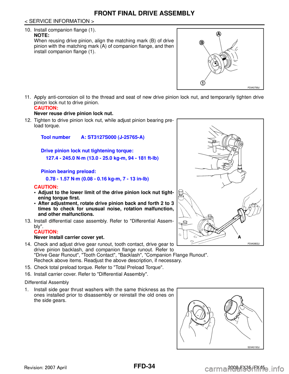
10. Install companion flange (1).NOTE:
When reusing drive pinion, align the matching mark (B) of drive
pinion with the matching mark (A) of companion flange, and then
install companion flange (1).
11. Apply anti-corrosion oil to the thread and seat of new drive pinion lock nut, and temporarily tighten drive
pinion lock nut to drive pinion.
CAUTION:
Never reuse drive pinion lock nut.
12. Tighten to drive pinion lock nut, while adjust pinion bearing pre- load torque.
CAUTION:
Adjust to the lower limit of the drive pinion lock nut tight-
ening torque first.
After adjustment, rotate dri ve pinion back and forth 2 to 3
times to check for unusual no ise, rotation malfunction,
and other malfunctions.
13. Install differential case assembly. Refer to "Differential Assem- bly".
CAUTION:
Never install carrier cover yet.
14. Check and adjust drive gear runout, tooth contact, drive gear to drive pinion backlash, and companion flange runout. Refer to
"Drive Gear Runout", "Tooth Contact" , "Backlash", "Companion Flange Runout".
Recheck above items. Readjust the above description, if necessary.
15. Check total preload torque. Refer to "Total Preload Torque".
16. Install carrier cover. Refer to "Differential Assembly".
Differential Assembly
1. Install side gear thrust washers with the same thickness as the ones installed prior to disassembly or reinstall the old ones on
the side gears.
PDIA0799J
Tool number A: ST3127S000 (J-25765-A)
Drive pinion lock nut tightening torque:
127.4 - 245.0 N·m (13.0 - 25.0 kg-m, 94 - 181 ft-lb)
Pinion bearing preload: 0.78 - 1.57 N·m (0.08 - 0.16 kg-m, 7 - 13 in-lb)
PDIA0802J
SDIA0193J
3AA93ABC3ACD3AC03ACA3AC03AC63AC53A913A773A893A873A873A8E3A773A983AC73AC93AC03AC3
3A893A873A873A8F3A773A9D3AAF3A8A3A8C3A863A9D3AAF3A8B3A8C
Page 2921 of 3924

GW-8
< SERVICE INFORMATION >
SQUEAK AND RATTLE TROUBLE DIAGNOSES
Most of these incidents can be repaired by adjusting, securing or insulatingthe item(s) or component(s) caus-
ing the noise.
SUNROOF/HEADLINING
Noises in the sunroof/headlining area c an often be traced to one of the following:
1. Sunroof lid, rail, linkage or seals making a rattle or light knockingnoise
2. Sunvisor shaft shaking in the holder
3. Front or rear windshield touching headlining and squeaking
Again, pressing on the components to stop the noise while duplicatingthe conditions can isolate most of these
incidents. Repairs usually consistof insulating with felt cloth tape.
SEATS
When isolating seat noise it's important to note the pos ition the seatis in and the load placed on the seat when
the noise is present. These conditionsshould be duplic ated when verifying and isolating the cause of the
noise.
Cause of seat noise include:
1. Headrest rods and holder
2. A squeak between the seat pad cushion and frame
3. The rear seatback lock and bracket
These noises can be isolated by moving or pressing on the suspectedcomponents while duplicating the condi-
tions under which the noise occurs.Most of these incidents can be repaired by repositioning the component
orapplying urethane tape to the contact area.
UNDERHOOD
Some interior noise may be caused by components under the hood or onthe engine wall. The noise is then
transmitted into the passenger compartment.
Causes of transmitted underhood noise include:
1. Any component mounted to the engine wall
2. Components that pass through the engine wall
3. Engine wall mounts and connectors
4. Loose radiator mounting pins
5. Hood bumpers out of adjustment
6. Hood striker out of adjustment
These noises can be difficult to isolate since they cannot be reached from the interior of the vehicle. The best
method is to secure, move or insulate one component at a time and test drive the \
vehicle. Also, engine RPM
or load can be changed to isolate the noise. Repairs can usually be made by moving, adjusting, securing, or
insulating the component causing the noise.
3AA93ABC3ACD3AC03ACA3AC03AC63AC53A913A773A893A873A873A8E3A773A983AC73AC93AC03AC3
3A893A873A873A8F3A773A9D3AAF3A8A3A8C3A863A9D3AAF3A8B3A8C
Page 3008 of 3924
SQUEAK AND RATTLE TROUBLE DIAGNOSESIP-7
< SERVICE INFORMATION >
C
DE
F
G H
J
K L
M A
B
IP
N
O P
Most of these incidents can be repaired by adjusting, se curing or insulating the item(s) or component(s) caus-
ing the noise.
SUNROOF/HEADLINING
Noises in the sunroof/headlining area can often be traced to one of the following:
1. Sunroof lid, rail, linkage or seals making a rattle or light knocking noise
2. Sunvisor shaft shaking in the holder
3. Front or rear windshield touching headlining and squeaking
Again, pressing on the components to stop the noise while duplicating the conditions can isolate most of these
incidents. Repairs usually consist of insulating with felt cloth tape.
SEATS
When isolating seat noise it's important to note the pos ition the seat is in and the load placed on the seat when
the noise is present. These conditions should be duplic ated when verifying and isolating the cause of the
noise.
Cause of seat noise include:
1. Headrest rods and holder
2. A squeak between the seat pad cushion and frame
3. The rear seatback lock and bracket
These noises can be isolated by moving or pressing on the suspected components while duplicating the con-
ditions under which the noise occurs. Most of thes e incidents can be repaired by repositioning the component
or applying urethane tape to the contact area.
UNDERHOOD
Some interior noise may be caused by components under the hood or on the engine wall. The noise is then
transmitted into the passenger compartment.
Causes of transmitted underhood noise include:
1. Any component mounted to the engine wall
2. Components that pass through the engine wall
3. Engine wall mounts and connectors
4. Loose radiator mounting pins
5. Hood bumpers out of adjustment
6. Hood striker out of adjustment
These noises can be difficult to isolate since they cannot be reached from the interior of the vehicle. The best
method is to secure, move or insulate one component at a time and test drive the vehicle. Also, engine RPM
or load can be changed to isolate the noise. Repairs c an usually be made by moving, adjusting securing, or
insulating the component causing the noise.
3AA93ABC3ACD3AC03ACA3AC03AC63AC53A913A773A893A873A873A8E3A773A983AC73AC93AC03AC3
3A893A873A873A8F3A773A9D3AAF3A8A3A8C3A863A9D3AAF3A8B3A8C
Page 3103 of 3924
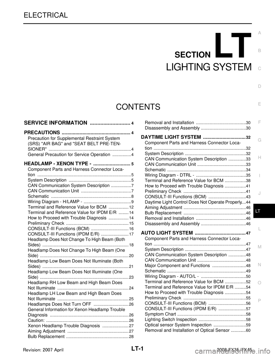
LT-1
ELECTRICAL
C
DE
F
G H
I
J
L
M
SECTION LT
A
B
LT
N
O P
CONTENTS
LIGHTING SYSTEM
SERVICE INFORMATION .. ..........................4
PRECAUTIONS .............................................. .....4
Precaution for Supplemental Restraint System
(SRS) "AIR BAG" and "SEAT BELT PRE-TEN-
SIONER" ............................................................. ......
4
General Precaution for Service Operation ................4
HEADLAMP - XENON TYPE - ............................5
Component Parts and Harness Connector Loca-
tion ...................................................................... ......
5
System Description ...................................................5
CAN Communication System Description .................7
CAN Communication Unit .........................................7
Schematic .................................................................8
Wiring Diagram - H/LAMP - .......................................9
Terminal and Reference Value for BCM .................12
Terminal and Reference Value for IPDM E/R .........14
How to Proceed with Trouble Diagnosis .................14
Preliminary Check ...................................................15
CONSULT-III Functions (BCM) ...............................16
CONSULT-III Functions (IPDM E/R) .......................17
Headlamp Does Not Change To High Beam (Both
Sides) ......................................................................
18
Headlamp Does Not Change To High Beam (One
Side) ........................................................................
20
Headlamp Low Beam Does Not Illuminate (Both
Sides) .................................................................. ....
21
Headlamp Low Beam Does Not Illuminate (One
Side) .................................................................... ....
23
Headlamp RH Low Beam and High Beam Does
Not Illuminate ..........................................................
24
Headlamp LH Low Beam and High Beam Does
Not Illuminate ..........................................................
25
Headlamps Does Not Turn OFF .............................26
General Information for Xenon Headlamp Trouble
Diagnosis ................................................................
26
Caution: ...................................................................26
Xenon Headlamp Trouble Diagnosis ......................27
Aiming Adjustment ..................................................27
Bulb Replacement ...................................................28
Removal and Installation ..................................... ....30
Disassembly and Assembly .....................................30
DAYTIME LIGHT SYSTEM ...............................32
Component Parts and Harness Connector Loca-
tion ....................................................................... ....
32
System Description ..................................................32
CAN Communication System Description ...............33
CAN Communication Unit ........................................33
Schematic ................................................................34
Wiring Diagram - DTRL - .........................................35
Terminal and Reference Value for BCM ..................38
How to Proceed with Trouble Diagnosis ..................41
Preliminary Check ...................................................41
CONSULT-III Functions (BCM) ...............................43
Daytime Light Control Does Not Operate Properly ....44
Aiming Adjustment ...................................................46
Bulb Replacement ...................................................46
Removal and Installation .........................................46
Disassembly and Assembly .....................................46
AUTO LIGHT SYSTEM .....................................47
Component Parts and Harness Connector Loca-
tion ...........................................................................
47
System Description ..................................................47
CAN Communication System Description ...............48
CAN Communication Unit ........................................48
Major Component and Functions ............................48
Schematic ................................................................49
Wiring Diagram - AUTO/L - .....................................50
Terminal and Reference Value for BCM ..................52
Terminal and Reference Value for IPDM E/R ..........54
How to Proceed with Trouble Diagnosis ..................54
Preliminary Check ...................................................55
CONSULT-III Functions (BCM) ...............................56
CONSULT-III Functions (IPDM E/R) .......................57
Symptom Chart ........................................................58
Lighting Switch Inspection .......................................58
Optical sensor System Inspection ...........................59
Removal and Installation of Optical Sensor .............60
3AA93ABC3ACD3AC03ACA3AC03AC63AC53A913A773A893A873A873A8E3A773A983AC73AC93AC03AC3
3A893A873A873A8F3A773A9D3AAF3A8A3A8C3A863A9D3AAF3A8B3A8C
Page 3177 of 3924
FRONT FOG LAMPLT-75
< SERVICE INFORMATION >
C
DE
F
G H
I
J
L
M A
B
LT
N
O P
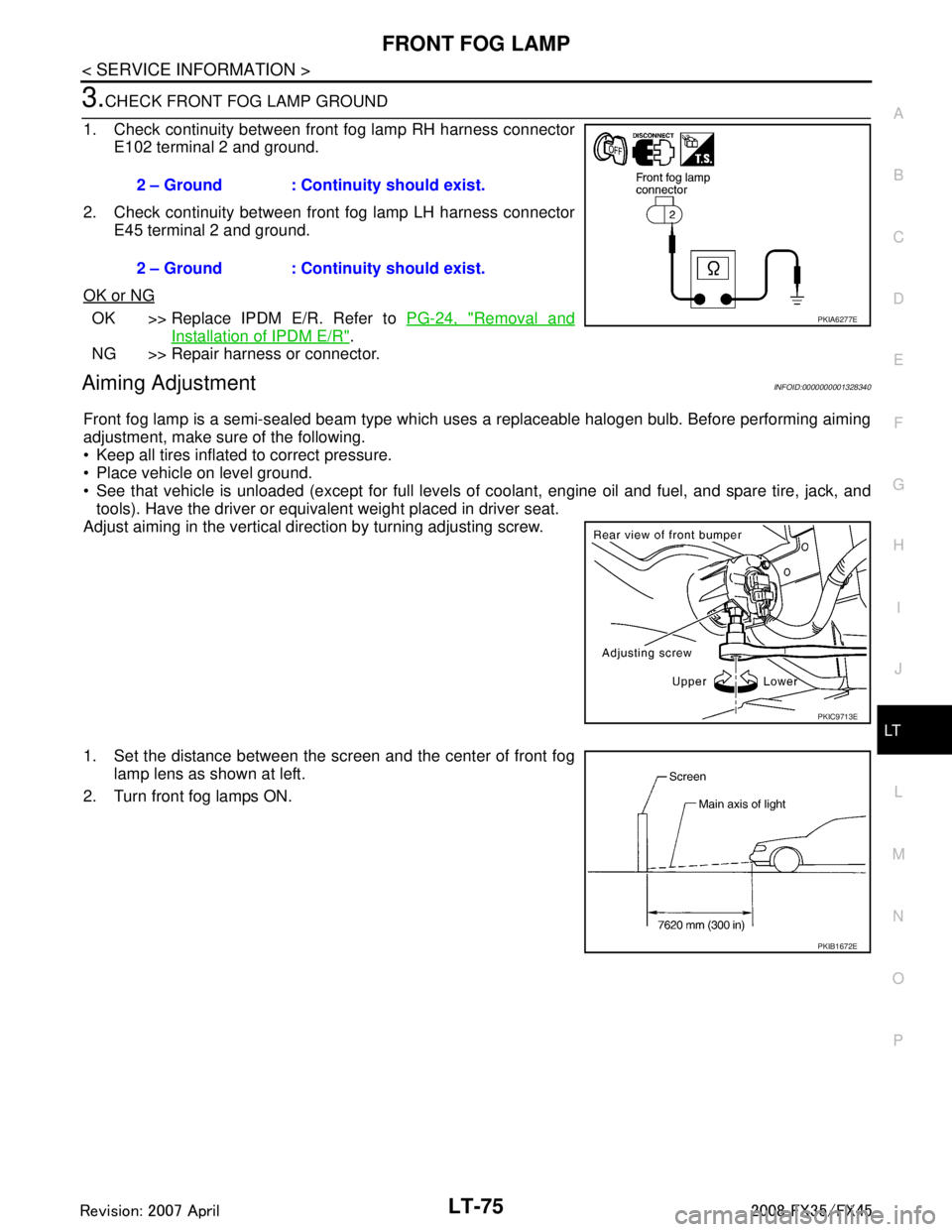
3.CHECK FRONT FOG LAMP GROUND
1. Check continuity between front fog lamp RH harness connector E102 terminal 2 and ground.
2. Check continuity between front fog lamp LH harness connector E45 terminal 2 and ground.
OK or NG
OK >> Replace IPDM E/R. Refer to PG-24, "Removal and
Installation of IPDM E/R".
NG >> Repair harness or connector.
Aiming AdjustmentINFOID:0000000001328340
Front fog lamp is a semi-sealed beam type which uses a replaceable halogen bulb. Before performing aiming
adjustment, make sure of the following.
Keep all tires inflated to correct pressure.
Place vehicle on level ground.
See that vehicle is unloaded (except for full levels of coolant, engine oil and fuel, and spare tire, jack, and tools). Have the driver or equivalent weight placed in driver seat.
Adjust aiming in the vertical direction by turning adjusting screw.
1. Set the distance between the scr een and the center of front fog
lamp lens as shown at left.
2. Turn front fog lamps ON. 2 – Ground : Continuity should exist.
2 – Ground : Continuity should exist.
PKIA6277E
PKIC9713E
PKIB1672E
3AA93ABC3ACD3AC03ACA3AC03AC63AC53A913A773A893A873A873A8E3A773A983AC73AC93AC03AC3
3A893A873A873A8F3A773A9D3AAF3A8A3A8C3A863A9D3AAF3A8B3A8C