2008 INFINITI FX35 seat adjustment
[x] Cancel search: seat adjustmentPage 3318 of 3924
MA-1
MAINTENANCE
C
DE
F
G H
I
J
K
M
SECTION MA
A
B
MA
N
O P
CONTENTS
MAINTENANCE
SERVICE INFORMATION .. ..........................2
PREPARATION .............................................. .....2
Special Service Tool ........................................... ......2
Commercial Service Tool ..........................................2
GENERAL MAINTENANCE ................................3
Explanation of General Maintenance .................. ......3
PERIODIC MAINTENANCE ................................5
Introduction of Periodic Maintenance .................. ......5
Schedule 1 ................................................................5
Schedule 2 ................................................................7
RECOMMENDED FLUIDS AND LUBRI-
CANTS .................................................................
9
Fluids and Lubricants .......................................... ......9
Engine Oil Recommendation ....................................9
Anti-Freeze Coolant Mixture Ratio ..........................10
ENGINE MAINTENANCE (VQ35DE ENGINE) ....11
Checking Drive Belts ........................................... ....11
Drive Belts Tension Adjustment ..............................11
Changing Engine Coolant .......................................12
Checking Fuel Line .................................................15
Changing Air Cleaner Filter .....................................15
Changing Engine Oil ...............................................15
Changing Oil Filter ..................................................16
Changing Spark Plugs (Platinum-Tipped Type) ......17
Checking EVAP Vapor Line ....................................18
ENGINE MAINTENANCE (VK45DE ENGINE) ....19
Checking Drive Belts ........................................... ....19
Tension Adjustment ................................................19
Changing Engine Coolant .......................................19
Checking Fuel Line .............................................. ....22
Changing Air Cleaner Filter .....................................22
Changing Engine Oil ................................................22
Changing Oil Filter ...................................................23
Changing Spark Plugs (Platinum-Tipped Type) ......24
Checking EVAP Vapor Line .....................................25
CHASSIS AND BODY MAINTENANCE ...........26
Checking Exhaust System ................................... ....26
Checking A/T Fluid ..................................................26
Changing A/T Fluid ..................................................27
Checking Transfer Fluid ..........................................28
Changing Transfer Fluid ..........................................28
Checking Propeller Shaft .........................................29
Checking Differential Gear Oil .................................29
Changing Differential Gear Oil .................................29
Balancing Wheels (Bonding Weight Type) ..............30
Tire Rotation ............................................................31
Checking Brake Fluid Level and Leaks ...................32
Checking Brake Line and Cables ............................32
Changing Brake Fluid ..............................................32
Checking Disc Brake ...............................................32
Checking Steering Gear and Linkage ......................33
Checking Power Steering Fluid and Line ................33
Axle and Suspension Parts .....................................34
Drive Shaft ...............................................................34
Lubricating Locks, Hinges and Hood Latch .............35
Checking Seat Belt, Buckles, Retractors, Anchors
and Adjusters ...........................................................
35
SERVICE DATA AND SPECIFICATIONS
(SDS) .................................................................
37
Standard and Limit ..................................................37
3AA93ABC3ACD3AC03ACA3AC03AC63AC53A913A773A893A873A873A8E3A773A983AC73AC93AC03AC3
3A893A873A873A8F3A773A9D3AAF3A8A3A8C3A863A9D3AAF3A8B3A8C
Page 3516 of 3924
RF-1
BODY
C
DE
F
G H
J
K L
M
SECTION RF
A
B
RF
N
O P
CONTENTS
ROOF
SERVICE INFORMATION .. ..........................2
PRECAUTIONS .............................................. .....2
Precaution for Supplemental Restraint System
(SRS) "AIR BAG" and "SEAT BELT PRE-TEN-
SIONER" ............................................................. ......
2
Precaution .................................................................2
PREPARATION ...................................................3
Special Service Tool ........................................... ......3
Commercial Service Tool ..........................................3
SQUEAK AND RATTLE TROUBLE DIAG-
NOSES ................................................................
4
Work Flow ........................................................... ......4
Generic Squeak and Rattle Troubleshooting ............6
Diagnostic Worksheet ...............................................8
SUNROOF ...................................................... ....10
Component Parts and Harness Connector Loca-
tion ...................................................................... ....
10
System Description .............................................. ....10
CAN Communication System Description ...............12
CAN Communication Unit ........................................12
Wiring Diagram - SROOF - ......................................13
Terminal and Reference Value for BCM ..................14
Terminal and Reference Value for Sunroof Motor
Assembly .................................................................
14
Work Flow ................................................................15
CONSULT-III Function (BCM) .................................15
Trouble Diagnosis Chart by Symptom .....................15
Check BCM Power Supply and Ground Circuit .......16
Check Sunroof Motor Assembly Power Supply
and Ground Circuit ..................................................
16
Check Sunroof Switch System ................................18
Check Door Switch ..................................................19
Wind Deflector Inspection ........................................21
Link and Wire Assembly ..........................................21
Fitting Adjustment ....................................................21
Removal and Installation .........................................22
3AA93ABC3ACD3AC03ACA3AC03AC63AC53A913A773A893A873A873A8E3A773A983AC73AC93AC03AC3
3A893A873A873A8F3A773A9D3AAF3A8A3A8C3A863A9D3AAF3A8B3A8C
Page 3522 of 3924
SQUEAK AND RATTLE TROUBLE DIAGNOSESRF-7
< SERVICE INFORMATION >
C
DE
F
G H
J
K L
M A
B
RF
N
O P
Most of these incidents can be repaired by adjusting, se curing or insulating the item(s) or component(s) caus-
ing the noise.
SUNROOF/HEADLINING
Noises in the sunroof/headlining area can often be traced to one of the following:
1. Sunroof lid, rail, linkage or seals making a rattle or light knocking noise
2. Sunvisor shaft shaking in the holder
3. Front or rear windshield touching headlining and squeaking
Again, pressing on the components to stop the noise while duplicating the conditions can isolate most of these
incidents. Repairs usually consist of insulating with felt cloth tape.
SEATS
When isolating seat noise it's important to note the pos ition the seat is in and the load placed on the seat when
the noise is present. These conditions should be duplic ated when verifying and isolating the cause of the
noise.
Cause of seat noise include:
1. Headrest rods and holder
2. A squeak between the seat pad cushion and frame
3. Rear seatback lock and bracket
These noises can be isolated by moving or pressing on the suspected components while duplicating the con-
ditions under which the noise occurs. Most of thes e incidents can be repaired by repositioning the component
or applying urethane tape to the contact area.
UNDERHOOD
Some interior noise may be caused by components under the hood or on the engine wall. The noise is then
transmitted into the passenger compartment.
Causes of transmitted underhood noise include:
1. Any component mounted to the engine wall
2. Components that pass through the engine wall
3. Engine wall mounts and connectors
4. Loose radiator mounting pins
5. Hood bumpers out of adjustment
6. Hood striker out of adjustment
These noises can be difficult to isolate since they cannot be reached from the interior of the vehicle. The best
method is to secure, move or insulate one component at a time and test drive the vehicle. Also, engine RPM
or load can be changed to isolate the noise. Repairs c an usually be made by moving, adjusting, securing, or
insulating the component causing the noise.
3AA93ABC3ACD3AC03ACA3AC03AC63AC53A913A773A893A873A873A8E3A773A983AC73AC93AC03AC3
3A893A873A873A8F3A773A9D3AAF3A8A3A8C3A863A9D3AAF3A8B3A8C
Page 3570 of 3924
RFD-28
< SERVICE INFORMATION >
REAR FINAL DRIVE ASSEMBLY
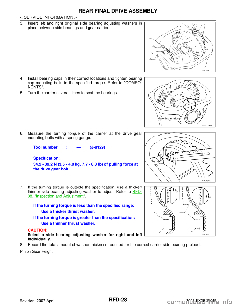
3. Insert left and right original side bearing adjusting washers inplace between side bearings and gear carrier.
4. Install bearing caps in their correct locations and tighten bearing cap mounting bolts to the specified torque. Refer to "COMPO-
NENTS".
5. Turn the carrier several times to seat the bearings.
6. Measure the turning torque of the carrier at the drive gear mounting bolts with a spring gauge.
7. If the turning torque is outside the specification, use a thicker/ thinner side bearing adjusting washer to adjust. Refer to RFD-
38, "Inspection and Adjustment".
CAUTION:
Select a side bearing adjust ing washer for right and left
individually.
8. Record the total amount of washer thickness required for the correct carrier side bearing preload.
Pinion Gear Height
SPD558
SDIA1795E
Tool number : — (J-8129)
Specification:
34.2 - 39.2 N (3.5 - 4.0 kg, 7.7 - 8.8 lb) of pulling force at
the drive gear bolt
SPD194A
If the turning torque is l ess than the specified range:
Use a thicker thrust washer.
If the turning torque is gr eater than the specification:
Use a thinner thrust washer.
SPD772
3AA93ABC3ACD3AC03ACA3AC03AC63AC53A913A773A893A873A873A8E3A773A983AC73AC93AC03AC3
3A893A873A873A8F3A773A9D3AAF3A8A3A8C3A863A9D3AAF3A8B3A8C
Page 3575 of 3924
REAR FINAL DRIVE ASSEMBLYRFD-33
< SERVICE INFORMATION >
CEF
G H
I
J
K L
M A
B
RFD
N
O P
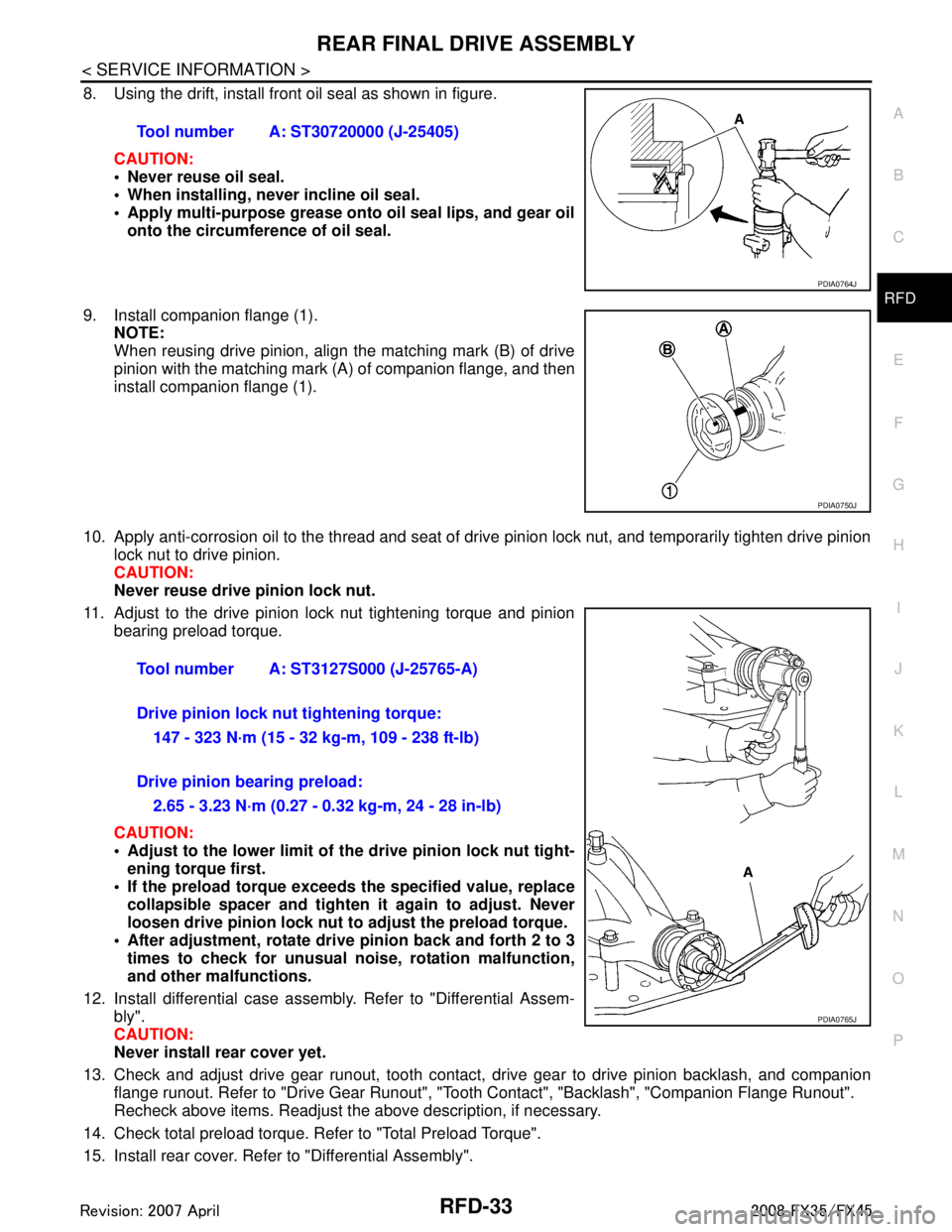
8. Using the drift, install front oil seal as shown in figure.
CAUTION:
Never reuse oil seal.
When installing, never incline oil seal.
Apply multi-purpose grease onto oil seal lips, and gear oilonto the circumference of oil seal.
9. Install companion flange (1). NOTE:
When reusing drive pinion, align the matching mark (B) of drive
pinion with the matching mark (A) of companion flange, and then
install companion flange (1).
10. Apply anti-corrosion oil to the thread and seat of drive pinion lock nut, and temporarily tighten drive pinion lock nut to drive pinion.
CAUTION:
Never reuse drive pinion lock nut.
11. Adjust to the drive pinion lock nut tightening torque and pinion bearing preload torque.
CAUTION:
Adjust to the lower limit of the drive pinion lock nut tight-
ening torque first.
If the preload torque exceeds the specified value, replace collapsible spacer and tighte n it again to adjust. Never
loosen drive pinion lock nut to adjust the preload torque.
After adjustment, rotate dri ve pinion back and forth 2 to 3
times to check for unusual no ise, rotation malfunction,
and other malfunctions.
12. Install differential case assembly. Refer to "Differential Assem- bly".
CAUTION:
Never install rear cover yet.
13. Check and adjust drive gear runout, tooth contact, drive gear to drive pinion backlash, and companion
flange runout. Refer to "Drive Gear Runout", "Tooth Contact", "Backlash", "Companion Flange Runout".
Recheck above items. Readjust the above description, if necessary.
14. Check total preload torque. Refer to "Total Preload Torque".
15. Install rear cover. Refer to "Differential Assembly". Tool number A: ST30720000 (J-25405)
PDIA0764J
PDIA0750J
Tool number A: ST3127S000 (J-25765-A)
Drive pinion lock nut tightening torque:
147 - 323 N·m (15 - 32 kg-m, 109 - 238 ft-lb)
Drive pinion bearing preload: 2.65 - 3.23 N·m (0.27 - 0.32 kg-m, 24 - 28 in-lb)
PDIA0765J
3AA93ABC3ACD3AC03ACA3AC03AC63AC53A913A773A893A873A873A8E3A773A983AC73AC93AC03AC3
3A893A873A873A8F3A773A9D3AAF3A8A3A8C3A863A9D3AAF3A8B3A8C
Page 3648 of 3924
SQUEAK AND RATTLE TROUBLE DIAGNOSESSE-9
< SERVICE INFORMATION >
C
DE
F
G H
J
K L
M A
B
SE
N
O P
Most of these incidents can be repaired by adjusting, se curing or insulating the item(s) or component(s) caus-
ing the noise.
SUNROOF/HEADLINING
Noises in the sunroof/headlining area can often be traced to one of the following:
1. Sunroof lid, rail, linkage or seals making a rattle or light knocking noise
2. Sun-visor shaft shaking in the holder
3. Front or rear windshield touching headlining and squeaking
Again, pressing on the components to stop the noise while duplicating the conditions can isolate most of these
incidents. Repairs usually consist of insulating with felt cloth tape.
SEATS
When isolating seat noise it's important to note the pos ition the seat is in and the load placed on the seat when
the noise is present. These conditions should be duplic ated when verifying and isolating the cause of the
noise.
Cause of seat noise include:
1. Headrest rods and holder
2. A squeak between the seat pad cushion and frame
3. The rear seatback lock and bracket
These noises can be isolated by moving or pressing on the suspected components while duplicating the con-
ditions under which the noise occurs. Most of thes e incidents can be repaired by repositioning the component
or applying urethane tape to the contact area.
UNDERHOOD
Some interior noise may be caused by components under the hood or on the engine wall. The noise is then
transmitted into the passenger compartment.
Causes of transmitted under-hood noise include:
1. Any component mounted to the engine wall
2. Components that pass through the engine wall
3. Engine wall mounts and connectors
4. Loose radiator mounting pins
5. Hood bumpers out of adjustment
6. Hood striker out of adjustment
These noises can be difficult to isolate since they cannot be reached from the interior of the vehicle. The best
method is to secure, move or insulate one component at a time and test drive the vehicle. Also, engine RPM
or load can be changed to isolate the noise. Repairs c an usually be made by moving, adjusting, securing, or
insulating the component causing the noise.
3AA93ABC3ACD3AC03ACA3AC03AC63AC53A913A773A893A873A873A8E3A773A983AC73AC93AC03AC3
3A893A873A873A8F3A773A9D3AAF3A8A3A8C3A863A9D3AAF3A8B3A8C
Page 3653 of 3924

SE-14
< SERVICE INFORMATION >
AUTOMATIC DRIVE POSITIONER
Selecting the memory
NOTE:
The driver's seat position and steering adjustment functions (see the following table) operate simultaneously in
the order of priority.
*: In conjunction with sliding the seat, the door mirrors are positioned.
ENTRY OPERATION
When the seat are on the exiting posit ions, the following operation moves the seat to the previous position
before the exiting operation.
EXITING OPERATION
At exit, the seat are automatica lly moved to the exiting position.
KEYFOB INTERLOCK OPERATION
Priority Function Priority Function
1 Seat sliding, door mirror LH/RH* 4 Seat reclining
2 Steering wheel telescoping 5 Seat lifter-FR
3 Steering wheel tilt 6 Seat lifter-RR
PIIA6137E
PIIA6135E
PIIA6136E
3AA93ABC3ACD3AC03ACA3AC03AC63AC53A913A773A893A873A873A8E3A773A983AC73AC93AC03AC3
3A893A873A873A8F3A773A9D3AAF3A8A3A8C3A863A9D3AAF3A8B3A8C
Page 3876 of 3924
WW-1
ELECTRICAL
C
DE
F
G H
I
J
L
M
SECTION WW
A
B
WW
N
O P
CONTENTS
WIPER, WASHER & HORN
SERVICE INFORMATION .. ..........................3
PRECAUTION ................................................ .....3
Precaution for Supplemental Restraint System
(SRS) "AIR BAG" and "SEAT BELT PRE-TEN-
SIONER" ............................................................. ......
3
Precaution for Procedure without Cowl Top Cover ......3
FRONT WIPER AND WASHER SYSTEM ..........4
Component Parts and Harness Connector Loca-
tion ...................................................................... ......
4
System Description ...................................................4
CAN Communication System Description .................6
CAN Communication Unit .........................................7
Schematic .................................................................7
Wiring Diagram - WIPER - ........................................8
Terminal and Reference Value for BCM .................10
Terminal and Reference Value for IPDM E/R .........14
How to Proceed with Trouble Diagnosis .................14
Preliminary Check ...................................................14
CONSULT-III Functions (BCM) ...............................15
CONSULT-III Functions (IPDM E/R) .......................16
Front Wiper Does Not Operate ...............................17
Front Wiper Does Not Return to Stop Position .......18
Only Front Wiper Low Does Not Operate ...............19
Only Front Wiper High Does Not Operate ...............20
Only Front Wiper Intermittent Does Not Operate ....21
Front Wiper Interval Time Is Not Controlled by Ve-
hicle Speed .............................................................
21
Front Wiper Intermittent Operation Switch Posi-
tion Cannot Be Adjusted .........................................
22
Wiper Does Not Wipe When Front Washer Oper-
ates .........................................................................
22
After Front Wiper Operate for 10 Seconds, They
Stop for 20 Seconds, and After Repeating the Op-
eration Five Times, They Become Inoperative ........
22
Front Wiper Does Not Stop .....................................23
Removal and Installation of Front Wiper Arms, Ad-
justment of Wiper Arms Stop Location ....................
23
Removal and Installation of Front Wiper Drive As-
sembly ................................................................. ....
24
Disassembly and Assembly of Front Wiper Drive
Assembly ............................................................. ....
25
Washer Nozzle Adjustment .....................................25
Washer Tube Layout ...............................................27
Removal and Installation of Front Washer Nozzle ....27
Removal and Installation of Front Washer Tube
Joint .........................................................................
27
Inspection of Washer Nozzle ...................................27
Inspection of Front Wiper and Washer Switch Cir-
cuit ...........................................................................
28
Removal and Installation of Front Wiper and
Washer Switch .........................................................
28
Removal and Installation of Washer Tank ...............28
Removal and Installation of Front and Rear Wash-
er Pump ...................................................................
29
REAR WIPER AND WASHER SYSTEM ..........30
Component Parts and Harness Connector Loca-
tion ...........................................................................
30
System Description ..................................................30
Wiring Diagram - WIP/ R - .......................................32
Terminal and Reference Value for BCM ..................33
How to Proceed with Trouble Diagnosis ..................35
Preliminary Check ...................................................36
CONSULT-III Functions (BCM) ...............................36
Rear Wiper Does Not Operate ................................37
Rear Wiper Does Not Return to Stop Position ........39
Only Rear Wiper ON Does Not Operate ..................40
Only Rear Wiper INT Does Not Operate .................40
Wiper Does Not Wipe When Rear Washer Oper-
ates ..........................................................................
40
Rear Wipers Do Not Stop ........................................40
Removal and Installation of Rear Wiper Arm, Ad-
justment of Wiper Arms Stop Location ....................
40
Removal and Installation of Rear Wiper Blade ........41
Removal and Installation of Rear Wiper Motor ........42
Washer Nozzle Adjustment .....................................43
Washer Tube Layout ...............................................43
Removal and Installation of Washer Nozzle ............43
Check Valve ............................................................44
3AA93ABC3ACD3AC03ACA3AC03AC63AC53A913A773A893A873A873A8E3A773A983AC73AC93AC03AC3
3A893A873A873A8F3A773A9D3AAF3A8A3A8C3A863A9D3AAF3A8B3A8C