2008 INFINITI FX35 transmission
[x] Cancel search: transmissionPage 837 of 3924

INTELLIGENT KEY SYSTEMBL-103
< SERVICE INFORMATION >
C
DE
F
G H
J
K L
M A
B
BL
N
O P
Diagnosis ProcedureINFOID:0000000001327846
WORK FLOW
CONSULT-III Functions (INTELLIGENT KEY)INFOID:0000000001327847
CONSULT-III has display and inspection functions for work support, self-diagnosis, data monitor, and control
unit part number by combining data reception and co mmand transmission via communication lines from the
Intelligent Key unit.
PIIA6736E
3AA93ABC3ACD3AC03ACA3AC03AC63AC53A913A773A893A873A873A8E3A773A983AC73AC93AC03AC3
3A893A873A873A8F3A773A9D3AAF3A8A3A8C3A863A9D3AAF3A8B3A8C
Page 900 of 3924

BL-166
< SERVICE INFORMATION >
VEHICLE SECURITY (THEFT WARNING) SYSTEM
When headlamp high relay (with built-in IPDM E/R) and horn relay are energized and then power is supplied
to headlamps (LH and RH) and horns (HIGH and LOW).
The headlamps flash and the horn sounds intermittently.
The alarm automatically turns off after 50 seconds, but will reactivate if the vehicle is tampered with again.
VEHICLE SECURITY SYSTEM DEACTIVATION
To deactivate the vehicle security system, a door or the back door must be unlocked with the key, key fob or
Intelligent Key.
When the key is used to unlock a door, BCM terminal 22 receives signal
from terminal 14 of the power window ma in switch (door lock and unlock switch).
When the BCM receives either one of these signals or unl ock signal from key cylinder switch, key fob or Intel-
ligent Key, the vehicle security sy stem is deactivated. (Disarmed phase)
PANIC ALARM OPERATION
Remote keyless entry system may or may not operat e vehicle security system (horn and headlamps) as
required.
When the remote keyless entry system is triggered, ground is supplied intermittently from IPDM E/R terminals
38 and 60.
When headlamp relay (which built-in IPDM E/R) and hor n relay are energized and then power is supplied to
headlamps (LH and RH) and horns (HIGH and LOW).
The headlamp flashes and the hor n sounds intermittently.
The alarm automatically turns off after 25 seconds or when BCM receives any signal from key fob or Intelligent
Key.
CAN Communication System DescriptionINFOID:0000000001327906
CAN (Controller Area Network) is a serial communication line for real time application. It is an on-vehicle mul-
tiplex communication line with high data communication s peed and excellent error detection ability. Many elec-
tronic control units are equipped onto a vehicle, and each control unit shares information and links with other
control units during operation (not independent). In CA N communication, control units are connected with 2
communication lines (CAN H line, CAN L line) allowing a high rate of information transmission with less wiring.
Each control unit transmits/receives data but selectively reads required data only.
CAN Communication UnitINFOID:0000000001327907
Refer to LAN-43, "CAN System Specification Chart".
3AA93ABC3ACD3AC03ACA3AC03AC63AC53A913A773A893A873A873A8E3A773A983AC73AC93AC03AC3
3A893A873A873A8F3A773A9D3AAF3A8A3A8C3A863A9D3AAF3A8B3A8C
Page 1027 of 3924
![INFINITI FX35 2008 Service Manual
BRC-12
< SERVICE INFORMATION >[VDC/TCS/ABS]
SYSTEM DESCRIPTION
Hydraulic Circuit Diagram
INFOID:0000000001327663
CAN CommunicationINFOID:0000000001327664
SYSTEM DESCRIPTION
CAN (Controller Area Netwo INFINITI FX35 2008 Service Manual
BRC-12
< SERVICE INFORMATION >[VDC/TCS/ABS]
SYSTEM DESCRIPTION
Hydraulic Circuit Diagram
INFOID:0000000001327663
CAN CommunicationINFOID:0000000001327664
SYSTEM DESCRIPTION
CAN (Controller Area Netwo](/manual-img/42/57017/w960_57017-1026.png)
BRC-12
< SERVICE INFORMATION >[VDC/TCS/ABS]
SYSTEM DESCRIPTION
Hydraulic Circuit Diagram
INFOID:0000000001327663
CAN CommunicationINFOID:0000000001327664
SYSTEM DESCRIPTION
CAN (Controller Area Network) is a serial communication line for real time application.It is an on-vehicle multi-
plex communication line with high data communication speed and excellent error detection ability. Many elec-
tronic control units are equipped onto a vehicle, and eac h control unit shares information and kinks with other
control units during operation (not independent). In CA N communication, control units are connected with 2
communication lines (CAN H line, CAN L line) allowing a high rate of information transmission with less wiring.
Each control unit transmits/receives data but se lectively reads required data only. Refer to LAN-43, "
CAN Sys-
tem Specification Chart".
SFIA1163E
3AA93ABC3ACD3AC03ACA3AC03AC63AC53A913A773A893A873A873A8E3A773A983AC73AC93AC03AC3
3A893A873A873A8F3A773A9D3AAF3A8A3A8C3A863A9D3AAF3A8B3A8C
Page 1176 of 3924

DI-50
< SERVICE INFORMATION >
A/T INDICATOR
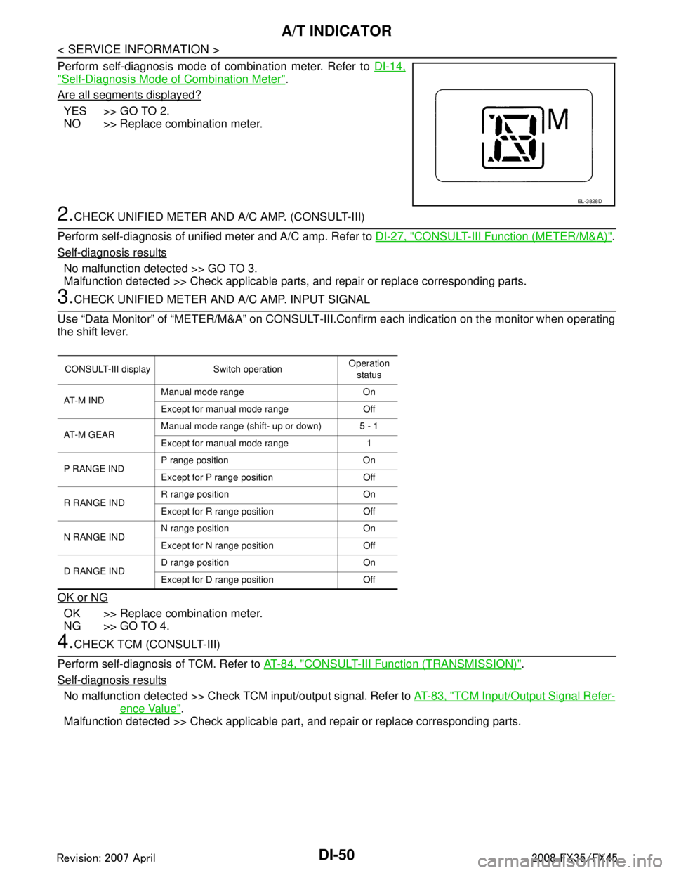
Perform self-diagnosis mode of combination meter. Refer to DI-14,
"Self-Diagnosis Mode of Combination Meter".
Are all segments displayed?
YES >> GO TO 2.
NO >> Replace combination meter.
2.CHECK UNIFIED METER AND A/C AMP. (CONSULT-III)
Perform self-diagnosis of unified meter and A/C amp. Refer to DI-27, "
CONSULT-III Function (METER/M&A)".
Self-diagnosis results
No malfunction detected >> GO TO 3.
Malfunction detected >> Check applicable parts, and repair or replace corresponding parts.
3.CHECK UNIFIED METER AND A/C AMP. INPUT SIGNAL
Use “Data Monitor” of “METER/M&A” on CONSULT-III. Confirm each indication on the monitor when operating
the shift lever.
OK or NG
OK >> Replace combination meter.
NG >> GO TO 4.
4.CHECK TCM (CONSULT-III)
Perform self-diagnosis of TCM. Refer to AT-84, "
CONSULT-III Function (TRANSMISSION)".
Self-diagnosis results
No malfunction detected >> Check TCM input/output signal. Refer to AT-83, "TCM Input/Output Signal Refer-
ence Value".
Malfunction detected >> Check applicable part, and repair or replace corresponding parts.
EL-3828D
CONSULT-III display Switch operation Operation
status
AT - M I N D Manual mode range On
Except for manual mode range Off
AT-M GEAR Manual mode range (shift- up or down) 5 - 1
Except for manual mode range 1
P RANGE IND P range position On
Except for P range position Off
R RANGE IND R range position On
Except for R range position Off
N RANGE IND N range position On
Except for N range position Off
D RANGE IND D range position On
Except for D range position Off
3AA93ABC3ACD3AC03ACA3AC03AC63AC53A913A773A893A873A873A8E3A773A983AC73AC93AC03AC3
3A893A873A873A8F3A773A9D3AAF3A8A3A8C3A863A9D3AAF3A8B3A8C
Page 1212 of 3924

DI-86
< SERVICE INFORMATION >
LANE DEPARTURE WARNING SYSTEM
Perform self-diagnosis of ABS actuator and electric unit (control unit). Refer to \
BRC-26, "CONSULT-III Func-
tions (ABS)".
Self
-diagnosis results
No malfunction detected >> GO TO 2.
Malfunction detected >> Check applicable parts, and repair or replace corresponding parts.
2.CHECK TCM (CONSULT-III)
Perform self-diagnosis of TCM. Refer to AT-84, "
CONSULT-III Function (TRANSMISSION)".
Self
-diagnosis results
No malfunction detected >> Replace LDW camera unit.
Malfunction detected >> Check applicable parts, and repair or replace corresponding parts.
DTC [C1B03] ABNRML TEMP DETECTINFOID:0000000001328507
1.COOLING CAMERA UNIT
1. Cooling camera unit.
2. Erase DTC and perform self-diagnosis the LDW camera unit.
Self
-diagnosis results
No malfunction detected >> INSPECTION END
Malfunction detected >> Replace LDW camera unit.
DTC [U1000] CAN COMM CIRCUITINFOID:0000000001328508
1.CHECK CAN COMMUNICATION
1. Turn ignition switch ON and wait for 2 seconds or more.
2. Check “Self Diagnostic Result” of “LDW”.
>> Go to “LAN SYSTEM”. Refer to LAN-43, "
CAN System Specification Chart".
DTC [U1010] CONTROL UNIT (CAN)INFOID:0000000001328509
Replace LDW camera unit, when “[U1010] CONTROL UNI T (CAN)” is displayed on self-diagnosis display.
LDW Chime Circuit InspectionINFOID:0000000001328510
1.CHECK LDW CHIME OPERATION
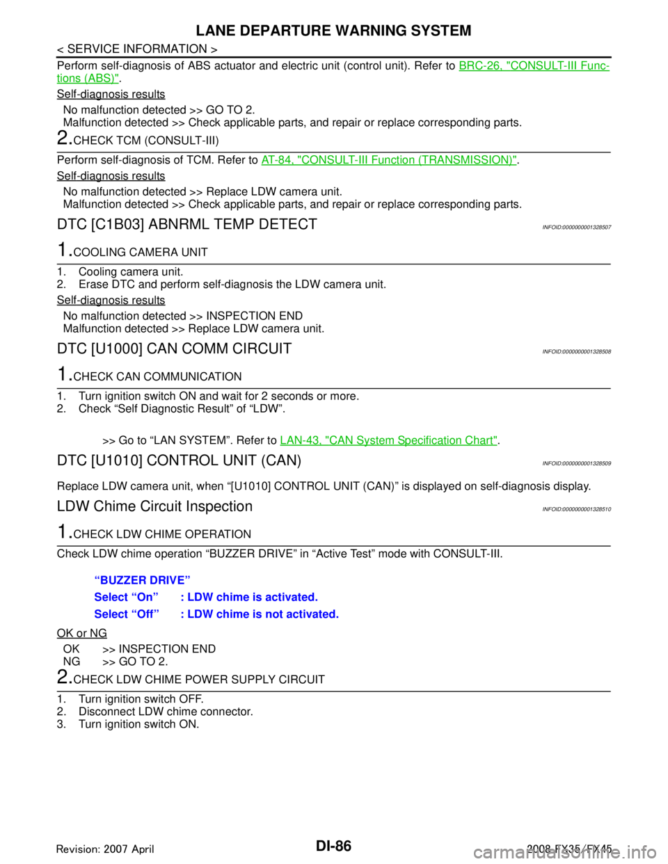
Check LDW chime operation “BUZZER DRIVE” in “Active Test” mode with CONSULT-III.
OK or NG
OK >> INSPECTION END
NG >> GO TO 2.
2.CHECK LDW CHIME POWER SUPPLY CIRCUIT
1. Turn ignition switch OFF.
2. Disconnect LDW chime connector.
3. Turn ignition switch ON. “BUZZER DRIVE”
Select “On” : LDW chime is activated.
Select “Off” : LDW chime is not activated.
3AA93ABC3ACD3AC03ACA3AC03AC63AC53A913A773A893A873A873A8E3A773A983AC73AC93AC03AC3
3A893A873A873A8F3A773A9D3AAF3A8A3A8C3A863A9D3AAF3A8B3A8C
Page 1219 of 3924

CAN COMMUNICATIONDI-93
< SERVICE INFORMATION >
C
DE
F
G H
I
J
L
M A
B
DI
N
O P
CAN COMMUNICATION
System DescriptionINFOID:0000000001328518
CAN (Controller Area Network) is a serial communication li ne for real time application. It is an on-vehicle mul-
tiplex communication line with high data communication speed and excellent error detection ability. Many elec-
tronic control units are equipped onto a vehicle, and each control unit shares information and links with other
control units during operation (not independent). In CAN communication, control units are connected with 2
communication lines (CAN-H line, CAN-L line) allowing a high rate of information transmission with less wiring.
Each control unit transmits/receives data but selectively reads required data only.
CAN Communication UnitINFOID:0000000001328519
Refer to LAN-43, "CAN System Specification Chart" in “LAN SYSTEM”.
3AA93ABC3ACD3AC03ACA3AC03AC63AC53A913A773A893A873A873A8E3A773A983AC73AC93AC03AC3
3A893A873A873A8F3A773A9D3AAF3A8A3A8C3A863A9D3AAF3A8B3A8C
Page 1265 of 3924
![INFINITI FX35 2008 Service Manual
PRECAUTIONSEC-25
< SERVICE INFORMATION > [VQ35DE]
C
D
E
F
G H
I
J
K L
M A
EC
NP
O
PRECAUTIONS
Precaution for Supplemental
Restraint System (SRS) "AIR BAG" and "SEAT BELT
PRE-TENSIONER"
INFOID:00000 INFINITI FX35 2008 Service Manual
PRECAUTIONSEC-25
< SERVICE INFORMATION > [VQ35DE]
C
D
E
F
G H
I
J
K L
M A
EC
NP
O
PRECAUTIONS
Precaution for Supplemental
Restraint System (SRS) "AIR BAG" and "SEAT BELT
PRE-TENSIONER"
INFOID:00000](/manual-img/42/57017/w960_57017-1264.png)
PRECAUTIONSEC-25
< SERVICE INFORMATION > [VQ35DE]
C
D
E
F
G H
I
J
K L
M A
EC
NP
O
PRECAUTIONS
Precaution for Supplemental
Restraint System (SRS) "AIR BAG" and "SEAT BELT
PRE-TENSIONER"
INFOID:0000000001612915
The Supplemental Restraint System such as “A IR BAG” and “SEAT BELT PRE-TENSIONER”, used along
with a front seat belt, helps to reduce the risk or severi ty of injury to the driver and front passenger for certain
types of collision. This system includes seat belt switch inputs and dual stage front air bag modules. The SRS
system uses the seat belt switches to determine the front air bag deployment, and may only deploy one front
air bag, depending on the severity of a collision and whether the front occupants are belted or unbelted.
Information necessary to service the system safely is included in the “SUPPLEMENTAL RESTRAINT SYS-
TEM” and “SEAT BELTS” of this Service Manual.
WARNING:
To avoid rendering the SRS inoper ative, which could increase the risk of personal injury or death in
the event of a collision which would result in air bag inflation, all maintenance must be performed by
an authorized NISSAN/INFINITI dealer.
Improper maintenance, including in correct removal and installation of the SRS, can lead to personal
injury caused by unintentional act ivation of the system. For removal of Spiral Cable and Air Bag
Module, see the “SUPPLEMEN TAL RESTRAINT SYSTEM”.
Do not use electrical test equipm ent on any circuit related to the SRS unless instructed to in this
Service Manual. SRS wiring harnesses can be identi fied by yellow and/or orange harnesses or har-
ness connectors.
Precaution for Procedur e without Cowl Top CoverINFOID:0000000001612935
When performing the procedure after removing cowl top cover, cover
the lower end of windshield with urethane, etc.
On Board Diagnosis (OBD) System of Engine and A/TINFOID:0000000001325891
The ECM has an on board diagnostic system. It will light up the malfunction indicator lamp (MIL) to warn the
driver of a malfunction causing emission deterioration.
CAUTION:
Be sure to turn the ignition switch OFF and di sconnect the negative battery cable before any repair
or inspection work. The op en/short circuit of related switches, sensors, solenoid valves, etc. will
cause the MIL to light up.
Be sure to connect and lock the connectors secure ly after work. A loose (unlocked) connector will
cause the MIL to light up due to the open circuit. (Be sure the connector is free from water, grease,
dirt, bent terminals, etc.)
Certain systems and components, especially those related to OBD, may use a new style slide-lock-
ing type harness connector. For descripti on and how to disconnect, refer to PG-68
.
Be sure to route and secure the harnesses properly after work. The interference of the harness with
a bracket, etc. may cause the MIL to li ght up due to the short circuit.
Be sure to connect rubber tubes properly afte r work. A misconnected or disconnected rubber tube
may cause the MIL to light up due to the malfuncti on of the EVAP system or fuel injection system,
etc.
Be sure to erase the unnecessary ma lfunction information (repairs completed) from the ECM and
TCM (Transmission control module) before returning the vehicle to the customer.
PIIB3706J
3AA93ABC3ACD3AC03ACA3AC03AC63AC53A913A773A893A873A873A8E3A773A983AC73AC93AC03AC3
3A893A873A873A8F3A773A9D3AAF3A8A3A8C3A863A9D3AAF3A8B3A8C
Page 1279 of 3924
![INFINITI FX35 2008 Service Manual
CAN COMMUNICATIONEC-39
< SERVICE INFORMATION > [VQ35DE]
C
D
E
F
G H
I
J
K L
M A
EC
NP
O
CAN COMMUNICATION
System DescriptionINFOID:0000000001325903
CAN (Controller Area Network) is a serial communica INFINITI FX35 2008 Service Manual
CAN COMMUNICATIONEC-39
< SERVICE INFORMATION > [VQ35DE]
C
D
E
F
G H
I
J
K L
M A
EC
NP
O
CAN COMMUNICATION
System DescriptionINFOID:0000000001325903
CAN (Controller Area Network) is a serial communica](/manual-img/42/57017/w960_57017-1278.png)
CAN COMMUNICATIONEC-39
< SERVICE INFORMATION > [VQ35DE]
C
D
E
F
G H
I
J
K L
M A
EC
NP
O
CAN COMMUNICATION
System DescriptionINFOID:0000000001325903
CAN (Controller Area Network) is a serial communication li
ne for real time application. It is an on-vehicle mul-
tiplex communication line with high data communication speed and excellent error detection ability. Many elec-
tronic control units are equipped onto a vehicle, and each control unit shares information and links with other
control units during operation (not independent). In CAN communication, control units are connected with 2
communication lines (CAN H line, CAN L line) allowing a high rate of information transmission with less wiring.
Each control unit transmits/receives data but selectively reads required data only.
Refer to LAN-43, "
CAN System Specification Chart", about CAN communication for detail.
3AA93ABC3ACD3AC03ACA3AC03AC63AC53A913A773A893A873A873A8E3A773A983AC73AC93AC03AC3
3A893A873A873A8F3A773A9D3AAF3A8A3A8C3A863A9D3AAF3A8B3A8C