2008 INFINITI FX35 clutch
[x] Cancel search: clutchPage 2912 of 3924

GI-50
< SERVICE INFORMATION >
TERMINOLOGY
Nonvolatile random access memory NVRAM ***
On board diagnostic system OBD system Self-diagnosis
Open loop OL Open loop
Oxidation catalyst OC Catalyst
Oxidation catalytic converter system OC system ***
Oxygen sensor O2S Exhaust gas sensor
Park position switch *** Park switch
Park/neutral position switch PNP switchPark/neutral switch
Inhibitor switch
Neutral position switch
Periodic trap oxidizer system PTOX system ***
Positive crankcase ventilation PCV Positive crankcase ventilation
Positive crankcase ventilation valve PCV valve PCV valve
Powertrain cont rol module PCM ***
Programmable read only memory PROM ***
Pulsed secondary air injection control sole-
noid valve PAIRC solenoid valve AIV control solenoid valve
Pulsed secondary air injection system PAIR system Air induction valve (AIV) control
Pulsed secondary air injection valve PAIR valve Air induction valve
Random access memory RAM ***
Read only memory ROM ***
Scan tool ST ***
Secondary air injection pump AIR pump ***
Secondary air injection system AIR system ***
Sequential multiport fuel injection system SFI system Sequential fuel injection
Service reminder indicator SRI ***
Simultaneous multiport fuel injection sys-
tem *** Simultaneous fuel injection
Smoke puff limiter system SPL system ***
Supercharger SC ***
Supercharger bypass SCB ***
System readiness test SRT ***
Thermal vacuum valve TVV Thermal vacuum valve
Three way catalyst TWC Catalyst
Three way catalytic converter system TWC system ***
Three way + oxidation catalyst TWC + OC Catalyst
Three way + oxidation catalytic converter
system TWC + OC system ***
Throttle body TB Throttle chamber
SPI body
Throttle body fuel injection system TBI system Fuel injection control
Throttle position TP Throttle position
Throttle position sensor TPS Throttle sensor
Throttle position switch TP switch Throttle switch
Torque converter clutch solenoid valve TCC solenoid valve Lock-up cancel solenoid
Lock-up solenoid
NEW TERM
NEW ACRONYM /
ABBREVIATION OLD TERM
3AA93ABC3ACD3AC03ACA3AC03AC63AC53A913A773A893A873A873A8E3A773A983AC73AC93AC03AC3
3A893A873A873A8F3A773A9D3AAF3A8A3A8C3A863A9D3AAF3A8B3A8C
Page 3006 of 3924

SQUEAK AND RATTLE TROUBLE DIAGNOSESIP-5
< SERVICE INFORMATION >
C
DE
F
G H
J
K L
M A
B
IP
N
O P
If the noise can be duplicated easily during the test drive, to help identify the source of the noise, try to dupli-
cate the noise with the vehicle stopped by doing one or all of the following:
1) Close a door.
2) Tap or push/pull around the area where the noise appears to be coming from.
3) Rev the engine.
4) Use a floor jack to recreate vehicle “twist”.
5) At idle, apply engine load (electrical load, half- clutch on M/T model, drive position on A/T model).
6) Raise the vehicle on a hoist and hit a tire with a rubber hammer.
Drive the vehicle and attempt to duplicate the conditions the customer states exist when the noise occurs.
If it is difficult to duplicate the noise, drive the vehicle slowly on an undulating or rough road to stress the vehicle body.
CHECK RELATED SERVICE BULLETINS
After verifying the customer concern or symptom, che ck ASIST for Technical Service Bulletins (TSBs) related
to that concern or symptom.
If a TSB relates to the symptom, follow the procedure to repair the noise.
LOCATE THE NOISE AND IDENTIFY THE ROOT CAUSE
1. Narrow down the noise to a general area. To help pinpoint the source of the noise, use a listening tool (Chassis Ear: J39570, Engine Ea r and mechanics stethoscope).
2. Narrow down the noise to a more specific area and identify the cause of the noise by:
Removing the components in the area that you suspect the noise is coming from.
Do not use too much force when removing clips and fasteners, otherwise clips and fastener can be broken
or lost during the repair, resulting in the creation of new noise.
Tapping or pushing/pulling the component that you suspect is causing the noise.
Do not tap or push/pull the component with excessive force, otherwise the noise will be eliminated only tem-
porarily.
Feeling for a vibration with your hand by touching t he component(s) that you suspect is (are) causing the
noise.
Placing a piece of paper between components that you suspect are causing the noise.
Looking for loose components and contact marks. Refer to IP-6, "
Generic Squeak and Rattle Troubleshooting".
REPAIR THE CAUSE
If the cause is a loose component, tighten the component securely.
If the cause is insufficient clearance between components:
- Separate components by repositioning or loosening and retightening the component, if possible.
- Insulate components with a suitable insulator such as urethane pads, foam blocks, felt cloth tape or ure-
thane tape. A NISSAN Squeak and Rattle Kit (J43980) is available through your authorized NISSAN Parts
Department.
CAUTION:
Do not use excessive force as many components are constructed of plastic and may be damaged.
NOTE:
Always check with the Parts Department for the latest parts information.
The following materials are contained in the NISS AN Squeak and Rattle Kit (J43980). Each item can be
ordered separately as needed.
URETHANE PADS [1.5 mm (0.059 in) thick]
Insulates connectors, harness, etc.
76268-9E005: 100 × 135 mm (3.94 × 5.31 in)/ 76884-71L01: 60 × 85 mm (2.36 × 3.35 in)/76884-71L02: 15 ×
25 mm (0.59 × 0.98 in)
INSULATOR (Foam blocks)
Insulates components from contact. Can be used to fill space behind a panel.
73982-9E000: 45 mm (1.77 in) thick, 50 × 50 mm (1.97 × 1.97 in)/73982-50Y00: 10 mm (0.39 in) think, 50
× 50 mm (1.97 × 1.97 in)
INSULATOR (Light foam block)
80845 - 71L00: 30 mm (1.18 in) thick, 30 × 50 mm (1.18 × 1.97 in)
FELT CLOTH TAPE
Used to insulate where movement does not oc cur.Ideal for instrument panel applications.
68370 - 4B000: 15 × 25 mm (0.59 × 0.98 in) pad / 68239-13E00: 5 mm (0.20 in) wide tape roll The following
materials, not found in the kit, can also be used to repair squeaks and rattles.
UHMW (TEFLON) TAPE
3AA93ABC3ACD3AC03ACA3AC03AC63AC53A913A773A893A873A873A8E3A773A983AC73AC93AC03AC3
3A893A873A873A8F3A773A9D3AAF3A8A3A8C3A863A9D3AAF3A8B3A8C
Page 3344 of 3924

CHASSIS AND BODY MAINTENANCEMA-27
< SERVICE INFORMATION >
C
DE
F
G H
I
J
K
M A
B
MA
N
O P
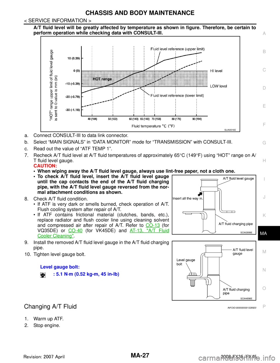
A/T fluid level will be greatly affected by temper ature as shown in figure. Therefore, be certain to
perform operation while checki ng data with CONSULT-III.
a. Connect CONSULT-III to data link connector.
b. Select “MAIN SIGNALS” in “DATA MONITOR” mode for “TRANSMISSION” with CONSULT-III.
c. Read out the value of “ATF TEMP 1”.
7. Recheck A/T fluid level at A/T fluid temperatures of approximately 65 °C (149 °F) using “HOT” range on A/
T fluid level gauge.
CAUTION:
When wiping away the A/T fluid level gauge, always use lint-free paper, not a cloth one.
To check A/T fluid level, inser t the A/T fluid level gauge
until the cap contacts the en d of the A/T fluid charging
pipe, with the A/T fluid level gauge reversed from the nor-
mal attachment conditions as shown.
8. Check A/T fluid condition. If ATF is very dark or smells burned, check operation of A/T.
Flush cooling system after repair of A/T.
If ATF contains frictional material (clutches, bands, etc.), replace radiator and flush cooler line using cleaning solvent
and compressed air after repair of A/T. Refer to CO-13
(for
VQ35DE) or CO-40
(for VK45DE) and AT-13, "A/T Fluid
Cooler Cleaning".
9. Install the removed A/T fluid level gauge in the A/T fluid charging pipe.
10. Tighten level gauge bolt.
Changing A/T FluidINFOID:0000000001328920
1. Warm up ATF.
2. Stop engine. Level gauge bolt:
: 5.1 N·m (0.52 kg-m, 45 in-lb)
SLIA0016E
SCIA2899E
SCIA4896E
3AA93ABC3ACD3AC03ACA3AC03AC63AC53A913A773A893A873A873A8E3A773A983AC73AC93AC03AC3
3A893A873A873A8F3A773A9D3AAF3A8A3A8C3A863A9D3AAF3A8B3A8C
Page 3381 of 3924

IPDM E/R (INTELLIGENT POWER DISTRIBUTION MODULE ENGINE ROOM)
PG-17
< SERVICE INFORMATION >
C
D E
F
G H
I
J
L
M A
B
PG
N
O P
IPDM E/R (INTELLIGENT POWER DISTRIBUTION MODULE ENGINE
ROOM)
System DescriptionINFOID:0000000001328870
IPDM E/R (Intelligent Power Distribution Module Engi ne Room) integrates the relay box and fuse block
which were originally placed in engine compartment. It c ontrols integrated relay via IPDM E/R control circuit.
IPDM E/R-integrated control circuit performs ON-OFF operation of relay, CAN communication control, oil
pressure switch signal, and hood switch signal reception, etc.
It controls operation of each electrical pa rt via ECM, BCM and CAN communication lines.
CAUTION:
None of the IPDM E/R-integr ated relays can be removed.
SYSTEMS CONTROLLED BY IPDM E/R
IPDM E/R receives a request signal fr om each control unit with CAN communication. It controls each system.
CAN COMMUNICATION LINE CONTROL
With CAN communication, by connecting each control uni t using two communication lines (CAN-L line, CAN-H
line), it is possible to transmit maximum amount of in formation with minimum wiring. Each control unit can
transmit and receive data, and reads necessary information only.
Fail- Safe Control
When CAN communication with other control units is impos sible, IPDM E/R performs fail-safe control. After
CAN communication recovers normally, it also returns to normal control.
Operation of control parts by IPDM E/R during fail-safe mode is as follows:
IPDM E/R STATUS CONTROL
In order to save power, IPDM E/R switches status by itself based on each operating condition.
1. CAN communication status CAN communication is normally performed with other control units.
Individual unit control by IPDM E/R is normally performed.
When sleep request signal is received from BCM, mode is switched to sleep waiting status.
2. Sleep waiting status Process to stop CAN communication is activated.
Control system Transmit control unit Control part
Lamp control BCM Headlamps (HI, LO)
Front fog lamps
Parking, license plate, side marker and tail lamps
Wiper control BCM Front wipers
Rear window defogger control BCM Rear window defogger
A/C compressor control ECM A/C compressor (magnet clutch)
Cooling fan control ECM Cooling fan
Horn control BCM Horn
Controlled system Fail-safe mode
Headlamp With the ignition switch ON, the headlamp (low) is ON.
With the ignition switch OFF, the headlamp (low) is OFF.
Parking, license plate side marker, and
tail lamps With the ignition switch ON, the parking, license plate, side marker and tail lamps is ON.
With the ignition switch OFF, the parking, license plate, side marker and tail lamps is OFF.
Cooling fan With the ignition switch ON, the cooling fan HI operates.
With the ignition switch OFF, the cooling fan stops.
Front wiper Until the ignition switch is turned OFF, the front wiper LO and HI remains in the same status
it was in just before fail-safe control was initiated.
Rear window defogger Rear window defogger relay OFF
A/C compressor A/C compressor OFF
Front fog lamps Front fog lamp relay OFF
3AA93ABC3ACD3AC03ACA3AC03AC63AC53A913A773A893A873A873A8E3A773A983AC73AC93AC03AC3
3A893A873A873A8F3A773A9D3AAF3A8A3A8C3A863A9D3AAF3A8B3A8C
Page 3384 of 3924

PG-20
< SERVICE INFORMATION >
IPDM E/R (INTELLIGENT POWER DISTRIBUTION MODULE ENGINE ROOM)
NOTE:
This item is displayed, but cannot be tested.
Auto Active TestINFOID:0000000001328875
DESCRIPTION
In auto active test mode, operation inspection can be performed when IPDM E/R sends a drive signal to the
following systems:
Rear window defogger
Front wipers
Parking, license plate, side marker and tail lamps
Front fog lamps
Headlamps (Hi, Lo)
A/C compressor (magnetic clutch)
Cooling fan
OPERATION PROCEDURE
1. Close hood and front door (passenger side), and then lift wiper arms away from windshield (to prevent
glass damage by wiper operation).
NOTE:
When auto active test is performed with hood opened, sprinkle water on windshield beforehand.
2. Turn ignition switch OFF.
3. Turn ignition switch ON, and within 20 seconds, pre ss drivers door switch 10 times (close other doors).
Then turn ignition switch OFF.
4. Turn ignition switch ON within 10 seconds after ignition switch OFF.
5. When auto active test mode is actuated, horn chir ps once oil pressure warning lamp starts blinking.
6. After a series of operations is repeated three times, auto active test is completed. NOTE:
When auto active test mode has to be cancelled halfway, turn ignition switch OFF.
CAUTION:
Be sure to inspect BL-38, "
Check Door Switch" when the auto active t est cannot be performed.
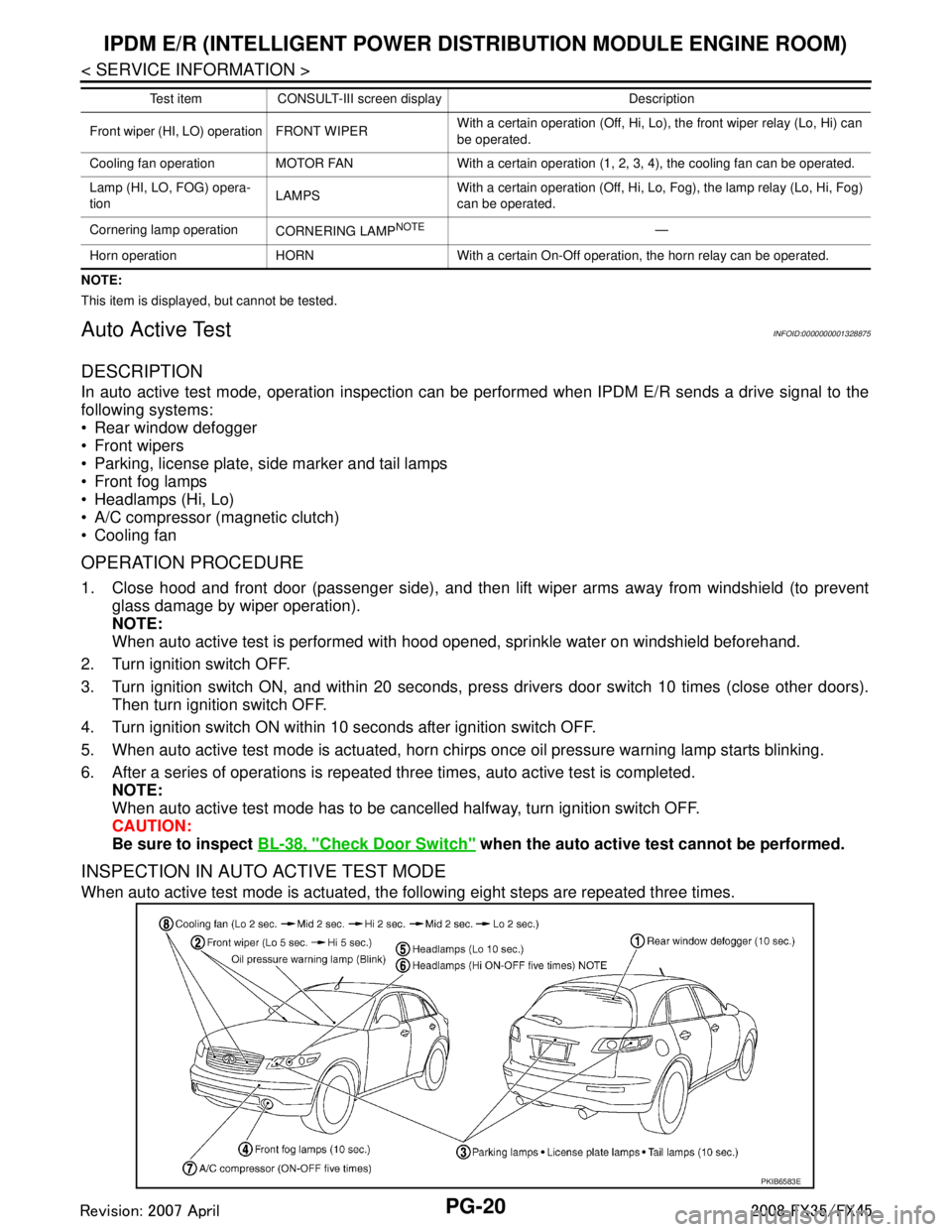
INSPECTION IN AUTO ACTIVE TEST MODE
When auto active test mode is actuated, the following eight steps are repeated three times.
Front wiper (HI, LO) operation FRONT WIPER With a certain operation (Off, Hi, Lo),
the front wiper relay (Lo, Hi) can
be operated.
Cooling fan operation MOTOR FAN With a certain operation (1, 2, 3, 4), the cooling fan can be operated.
Lamp (HI, LO, FOG) opera-
tion LAMPSWith a certain operation (Off, Hi, Lo, Fog), the lamp relay (Lo, Hi, Fog)
can be operated.
Cornering lamp operation CORNERING LAMP
NOTE—
Horn operation HORN With a certain On-Off operation, the horn relay can be operated. Test item CONSULT-III screen display Description
PKIB6583E
3AA93ABC3ACD3AC03ACA3AC03AC63AC53A913A773A893A873A873A8E3A773A983AC73AC93AC03AC3
3A893A873A873A8F3A773A9D3AAF3A8A3A8C3A863A9D3AAF3A8B3A8C
Page 3385 of 3924

IPDM E/R (INTELLIGENT POWER DISTRIBUTION MODULE ENGINE ROOM)
PG-21
< SERVICE INFORMATION >
C
D E
F
G H
I
J
L
M A
B
PG
N
O P
NOTE:
Turns ON-OFF the solenoid to switch Hi/Lo. In this case, the bulb does not illuminate.
Concept of Auto Active Test
IPDM E/R actuates auto active test mode when it re ceives door switch signal from BCM via CAN communi-
cation line. Therefore, when auto active test mode is activated successfully, CAN communication between
IPDM E/R and BCM is normal.
If any of systems controlled by IPDM E/R cannot be operated, possible cause can be easily diagnosed using
auto active test.
Diagnosis chart in auto active test mode
Symptom Inspection contents Possible cause
Any of front wipers, tail
and parking lamps, front
fog lamps, and head
lamps (Hi, Lo) do not op-
erate. Perform auto active
test. Does system in
question operate?YES BCM signal input system malfunction
NO Lamp/wiper motor malfunction
Lamp/wiper motor ground circuit malfunction
Harness/connector malfunction between IPDM E/R and system in question
IPDM E/R (integrated relay) malfunction
Rear window defogger
does not operate. Perform auto active
test. Does rear win-
dow defogger oper-
ate?YES BCM signal input circuit malfunction
NO Rear window defogger relay malfunction
Harness/connector malfunction between IPDM E/R and rear window de-
fogger relay.
Open circuit of rear window defogger
IPDM E/R malfunction
A/C compressor does
not operate. Perform auto active
test. Does magnetic
clutch operate?YES
BCM signal input circuit malfunction
CAN communication signal between BCM and ECM.
CAN communication signal between ECM and IPDM E/R
NO Magnetic clutch malfunction
Harness/connector malfunction between IPDM E/R and magnetic clutch
IPDM E/R (integrated relay) malfunction
Cooling fan does not op-
erate. Perform auto active
test. Does cooling
fan operate?YES
ECM signal input circuit
CAN communication signal between ECM and IPDM E/R
NO Cooling fan motor malfunction
Harness/connector malfunction between IPDM E/R and cooling fan motor
IPDM E/R (integrated relay) malfunction
Oil pressure warning
lamp does not operate. Perform auto active
test. Does oil pres-
sure warning lamp
blink?YES
Harness/connector malfunction between IPDM E/R and oil pressure switch
Oil pressure switch malfunction
IPDM E/R malfunction
NO CAN communication signal between BCM and unified meter and A/C amp.
Combination meter
3AA93ABC3ACD3AC03ACA3AC03AC63AC53A913A773A893A873A873A8E3A773A983AC73AC93AC03AC3
3A893A873A873A8F3A773A9D3AAF3A8A3A8C3A863A9D3AAF3A8B3A8C
Page 3520 of 3924

SQUEAK AND RATTLE TROUBLE DIAGNOSESRF-5
< SERVICE INFORMATION >
C
DE
F
G H
J
K L
M A
B
RF
N
O P
If the noise can be duplicated easily during the test drive, to help identify the source of the noise, try to dupli-
cate the noise with the vehicle stopped by doing one or all of the following:
1) Close a door.
2) Tap or push/pull around the area where the noise appears to be coming from.
3) Rev the engine.
4) Use a floor jack to recreate vehicle “twist”.
5) At idle, apply engine load (electrical load, half- clutch on M/T model, drive position on A/T model).
6) Raise the vehicle on a hoist and hit a tire with a rubber hammer.
Drive the vehicle and attempt to duplicate the conditions the customer states exist when the noise occurs.
If it is difficult to duplicate the noise, drive the vehicle slowly on an undulating or rough road to stress the vehicle body.
CHECK RELATED SERVICE BULLETINS
After verifying the customer concern or symptom, che ck ASIST for Technical Service Bulletins (TSBs) related
to that concern or symptom.
If a TSB relates to the symptom, follow the procedure to repair the noise.
LOCATE THE NOISE AND IDENTIFY THE ROOT CAUSE
1. Narrow down the noise to a general area. To help pinpoint the source of the noise, use a listening tool (Chassis Ear: J39570, Engine Ea r and mechanics stethoscope).
2. Narrow down the noise to a more specific area and identify the cause of the noise by:
removing the components in the area that you suspect the noise is coming from. Do not use too much force when removing clips and fasteners, otherwise clips and fastener can be broken
or lost during the repair, resulting in the creation of new noise.
tapping or pushing/pulling the component that you suspect is causing the noise.
Do not tap or push/pull the component with excessive force, otherwise the noise will be eliminated only tem-
porarily.
feeling for a vibration with your hand by touching the component(s) that you suspect is (are) causing the
noise.
placing a piece of paper between components that you suspect are causing the noise.
looking for loose components and contact marks. Refer to RF-6, "
Generic Squeak and Rattle Troubleshooting".
REPAIR THE CAUSE
If the cause is a loose component, tighten the component securely.
If the cause is insufficient clearance between components:
- separate components by repositioning or loos ening and retightening the component, if possible.
- insulate components with a suitable insulator such as urethane pads, foam blocks, felt cloth tape or urethane tape. A Nissan Squeak and Rattle Kit (J43980) is available through your authorized Nissan Parts Depart-
ment.
CAUTION:
Do not use excessive force as many components are constructed of plastic and may be damaged.
NOTE:
Always check with the Parts Department for the latest parts information.
The following materials are contained in the Nissan Squeak and Rattle Kit (J43980). Each item can be ordered
separately as needed.
URETHANE PADS [1.5 mm (0.059 in) thick]
Insulates connectors, harness, etc.
76268-9E005: 100 × 135 mm (3.94 × 5.31 in)/76884-71L01: 60 × 85 mm (2.36 × 3.35 in)/76884-71L02: 15 ×
25 mm (0.59 × 0.98 in)
INSULATOR (Foam blocks)
Insulates components from contact.Can be used to fill space behind a panel.
73982-9E000: 45 mm (1.77 in) thick, 50 × 50 mm (1.97 × 1.97 in)/73982-50Y00: 10 mm (0.39 in) thick, 50
× 50 mm (1.97 × 1.97 in)
INSULATOR (Light foam block)
80845-71L00: 30 mm (1.18 in) thick, 30 × 50 mm (1.18 × 1.97 in)
FELT CLOTHTAPE
Used to insulate where movement does not occur. Ideal for instrument panel applications.
68370-4B000: 15 × 25 mm (0.59 × 0.98 in) pad/68239-13E00: 5 mm (0.20 in) wide tape roll
The following materials, not found in the kit, can also be used to repair squeaks and rattles.
UHMW(TEFLON) TAPE
3AA93ABC3ACD3AC03ACA3AC03AC63AC53A913A773A893A873A873A8E3A773A983AC73AC93AC03AC3
3A893A873A873A8F3A773A9D3AAF3A8A3A8C3A863A9D3AAF3A8B3A8C
Page 3625 of 3924

SC-16
< SERVICE INFORMATION >
STARTING SYSTEM
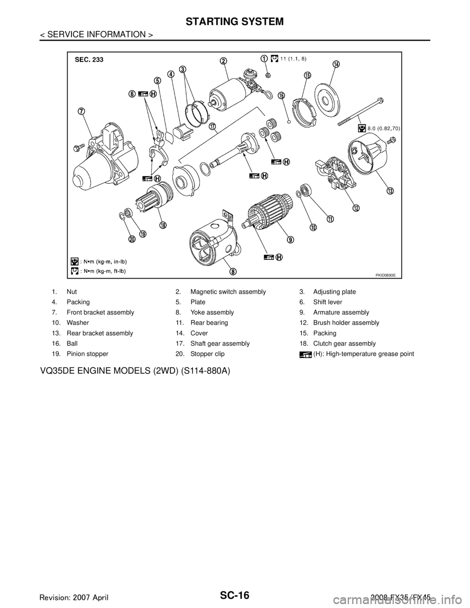
VQ35DE ENGINE MODELS (2WD) (S114-880A)
1. Nut 2. Magnetic switch assembly 3. Adjusting plate
4. Packing 5. Plate 6. Shift lever
7. Front bracket assembly 8. Yoke assembly 9. Armature assembly
10. Washer 11. Rear bearing 12. Brush holder assembly
13. Rear bracket assembly 14. Cover 15. Packing
16. Ball 17. Shaft gear assembly 18. Clutch gear assembly
19. Pinion stopper 20. Stopper clip (H): High-temperature grease point
PKID0693E
3AA93ABC3ACD3AC03ACA3AC03AC63AC53A913A773A893A873A873A8E3A773A983AC73AC93AC03AC3
3A893A873A873A8F3A773A9D3AAF3A8A3A8C3A863A9D3AAF3A8B3A8C