2008 INFINITI FX35 ABS
[x] Cancel search: ABSPage 2315 of 3924
![INFINITI FX35 2008 Service Manual
DTC P1574 ICC VEHICLE SPEED SENSOREC-1075
< SERVICE INFORMATION > [VK45DE]
C
D
E
F
G H
I
J
K L
M A
EC
NP
O
DTC P1574 ICC VEHIC
LE SPEED SENSOR
Component DescriptionINFOID:0000000001326949
The ECM rec INFINITI FX35 2008 Service Manual
DTC P1574 ICC VEHICLE SPEED SENSOREC-1075
< SERVICE INFORMATION > [VK45DE]
C
D
E
F
G H
I
J
K L
M A
EC
NP
O
DTC P1574 ICC VEHIC
LE SPEED SENSOR
Component DescriptionINFOID:0000000001326949
The ECM rec](/manual-img/42/57017/w960_57017-2314.png)
DTC P1574 ICC VEHICLE SPEED SENSOREC-1075
< SERVICE INFORMATION > [VK45DE]
C
D
E
F
G H
I
J
K L
M A
EC
NP
O
DTC P1574 ICC VEHIC
LE SPEED SENSOR
Component DescriptionINFOID:0000000001326949
The ECM receives two vehicle speed signals via CAN comm unication line. One is sent from “unified meter and
A/C amp.”, and the other is from TCM (Transmission control module). The ECM uses these signals for ICC
control. Refer to ACS-7
for ICC functions.
On Board Diagnosis LogicINFOID:0000000001326950
This self-diagnosis has the on e trip detection logic.
The MIL will not light up for this diagnosis.
NOTE:
If DTC P1574 is displayed with DTC U1000, U1001, first perform th e trouble diagnosis for DTC U1000,
U1001. Refer to EC-724
.
If DTC P1574 is displayed with DTC U1010, first pe rform the trouble diagnosis for DTC U1010. Refer
to EC-726
.
If DTC P1574 is displayed with DT C P0500, first perform the trouble diagnosis for DTC P0500. Refer
to EC-992
.
If DTC P1574 is displayed with DTC P0605, firs t perform the trouble diagnosis for DTC P0605.
Refer to EC-1007
.
DTC Confirmation ProcedureINFOID:0000000001326951
CAUTION:
Always drive vehicle at a safe speed.
NOTE:
If DTC Confirmation Procedure has been previously conduc ted, always turn ignition switch OFF and wait at
least 10 seconds before conducting the next test.
TESTING CONDITION:
Step 3 may be conducted with the dr ive wheels lifted in the shop or by driving the vehicle. If a road test
is expected to be easier, it is unnecessary to lift the vehicle.
1. Start engine (VDC switch OFF).
2. Drive the vehicle at more than 40 km/h (25MPH).
3. Check DTC.
4. If DTC is detected, go to EC-1075, "
Diagnosis Procedure".
Diagnosis ProcedureINFOID:0000000001326952
1.CHECK DTC WITH TCM
Check DTC with TCM. Refer to AT- 3 8
.
OK or NG
OK >> GO TO 2.
NG >> Perform trouble shooting relevant to DTC indicated.
2.CHECK DTC WITH “ABS ACTUATOR AND ELECTRIC UNIT (CONTROL UNIT)”
Refer to BRC-13
.
OK or NG
DTC No. Trouble diagnosis
name DTC detecting condition Possible cause
P1574
1574 ICC vehicle speed
sensor ECM detects a difference between two vehicle
speed signals is out of the specified range. Harness or connectors
(The CAN communication line is open or
shorted.)
Unified meter and A/C amp.
ABS actuator and electric unit (control unit)
Wheel sensor
TCM
ECM
3AA93ABC3ACD3AC03ACA3AC03AC63AC53A913A773A893A873A873A8E3A773A983AC73AC93AC03AC3
3A893A873A873A8F3A773A9D3AAF3A8A3A8C3A863A9D3AAF3A8B3A8C
Page 2317 of 3924
![INFINITI FX35 2008 Service Manual
DTC P1574 ASCD VEHICLE SPEED SENSOR
EC-1077
< SERVICE INFORMATION > [VK45DE]
C
D
E
F
G H
I
J
K L
M A
EC
NP
O
DTC P1574 ASCD VEHIC
LE SPEED SENSOR
Component DescriptionINFOID:0000000001326953
The ECM INFINITI FX35 2008 Service Manual
DTC P1574 ASCD VEHICLE SPEED SENSOR
EC-1077
< SERVICE INFORMATION > [VK45DE]
C
D
E
F
G H
I
J
K L
M A
EC
NP
O
DTC P1574 ASCD VEHIC
LE SPEED SENSOR
Component DescriptionINFOID:0000000001326953
The ECM](/manual-img/42/57017/w960_57017-2316.png)
DTC P1574 ASCD VEHICLE SPEED SENSOR
EC-1077
< SERVICE INFORMATION > [VK45DE]
C
D
E
F
G H
I
J
K L
M A
EC
NP
O
DTC P1574 ASCD VEHIC
LE SPEED SENSOR
Component DescriptionINFOID:0000000001326953
The ECM receives two vehicle speed sensor signals via CAN communication line. One is sent from “unified
meter and A/C amp.”, and the other is from TCM (Tr ansmission control module). The ECM uses these signals
for ASCD control. Refer to EC-615
for ASCD functions.
On Board Diagnosis LogicINFOID:0000000001326954
This self-diagnosis has the on e trip detection logic.
The MIL will not light up for this diagnosis.
NOTE:
If DTC P1574 is displayed with DTC U1000, U1001, first perform th e trouble diagnosis for DTC U1000,
U1001. Refer to EC-724
.
If DTC P1574 is displayed with DTC U1010, first pe rform the trouble diagnosis for DTC U1010. Refer
to EC-726
.
If DTC P1574 is displayed with DT C P0500, first perform the trouble diagnosis for DTC P0500. Refer
to EC-992
If DTC P1574 is displayed with DT C P0605, first perform the trouble diagnosis for DTC P0605. Refer
to EC-1007
DTC Confirmation ProcedureINFOID:0000000001326955
CAUTION:
Always drive vehicle at a safe speed.
NOTE:
If DTC Confirmation Procedure has been previously conduc ted, always turn ignition switch OFF and wait at
least 10 seconds before conducting the next test.
TESTING CONDITION:
Step 3 may be conducted with the dr ive wheels lifted in the shop or by driving the vehicle. If a road test
is expected to be easier, it is unnecessary to lift the vehicle.
1. Start engine (VDC switch OFF).
2. Drive the vehicle at more than 40 km/h (25 MPH).
3. Check DTC.
4. If DTC is detected, go to EC-1077, "
Diagnosis Procedure".
Diagnosis ProcedureINFOID:0000000001326956
1.CHECK DTC WITH TCM
Check DTC with TCM. Refer to AT- 3 8
.
OK or NG
OK >> GO TO 2.
NG >> Perform trouble shooting relevant to DTC indicated.
2.CHECK DTC WITH “ABS ACTUATOR AND ELECTRIC UNIT (CONTROL UNIT)”
Refer to BRC-13
.
OK or NG
DTC No. Trouble diagnosis
name DTC detecting condition Possible cause
P1574
1574 ASCD vehicle speed
sensor ECM detects a difference between two vehicle
speed signals is out of the specified range. Harness or connectors
(The CAN communication line is open or
shorted.)
Unified meter and A/C amp.
ABS actuator and electric unit (control unit)
Wheel sensor
TCM
ECM
3AA93ABC3ACD3AC03ACA3AC03AC63AC53A913A773A893A873A873A8E3A773A983AC73AC93AC03AC3
3A893A873A873A8F3A773A9D3AAF3A8A3A8C3A863A9D3AAF3A8B3A8C
Page 2451 of 3924

EI-14
< SERVICE INFORMATION >
FRONT BUMPER
FRONT BUMPER
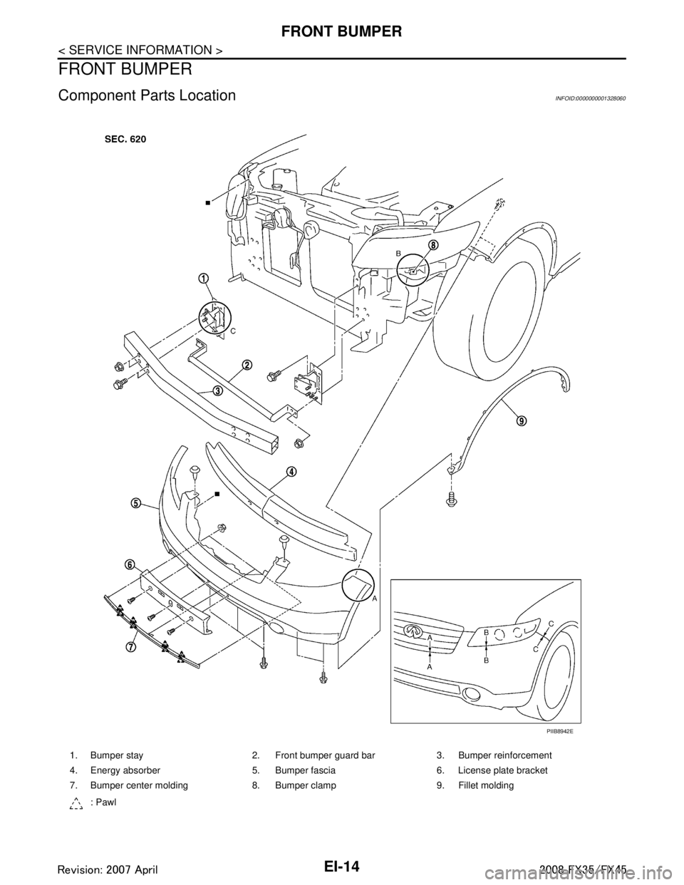
Component Parts LocationINFOID:0000000001328060
1. Bumper stay 2. Front bumper guard bar 3. Bumper reinforcement
4. Energy absorber 5. Bumper fascia 6. License plate bracket
7. Bumper center molding 8. Bumper clamp 9. Fillet molding: Pawl
PIIB8942E
3AA93ABC3ACD3AC03ACA3AC03AC63AC53A913A773A893A873A873A8E3A773A983AC73AC93AC03AC3
3A893A873A873A8F3A773A9D3AAF3A8A3A8C3A863A9D3AAF3A8B3A8C
Page 2452 of 3924

FRONT BUMPEREI-15
< SERVICE INFORMATION >
C
DE
F
G H
J
K L
M A
B
EI
N
O P
Removal and InstallationINFOID:0000000001529395
CAUTION:
Bumper fascia is made of resin. Do not apply strong force to it, and be careful to prevent contact with
oil.
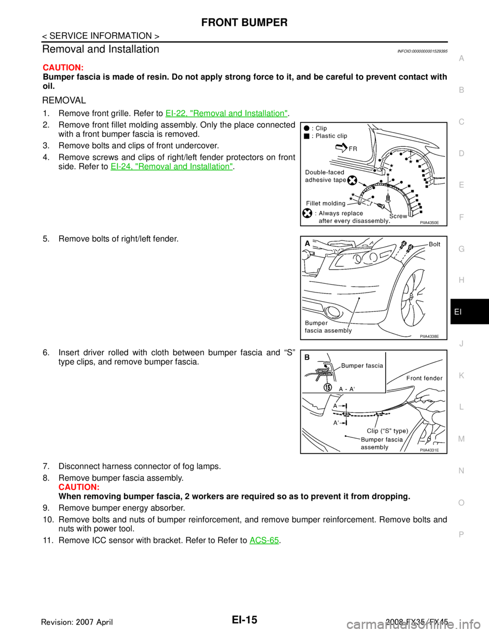
REMOVAL
1. Remove front grille. Refer to EI-22, "Removal and Installation".
2. Remove front fillet molding assembly. Only the place connected with a front bumper fascia is removed.
3. Remove bolts and clips of front undercover.
4. Remove screws and clips of right/left fender protectors on front side. Refer to EI-24, "
Removal and Installation".
5. Remove bolts of right/left fender.
6. Insert driver rolled with cloth between bumper fascia and “S” type clips, and remove bumper fascia.
7. Disconnect harness connector of fog lamps.
8. Remove bumper fascia assembly. CAUTION:
When removing bumper fascia, 2 workers are required so as to prevent it from dropping.
9. Remove bumper energy absorber.
10. Remove bolts and nuts of bumper reinforcement, and remove bumper reinforcement. Remove bolts and nuts with power tool.
11. Remove ICC sensor with bracket. Refer to Refer to ACS-65
.
PIIA4350E
PIIA4338E
PIIA4331E
3AA93ABC3ACD3AC03ACA3AC03AC63AC53A913A773A893A873A873A8E3A773A983AC73AC93AC03AC3
3A893A873A873A8F3A773A9D3AAF3A8A3A8C3A863A9D3AAF3A8B3A8C
Page 2455 of 3924

EI-18
< SERVICE INFORMATION >
REAR BUMPER
Removal and Installation
INFOID:0000000001529396
CAUTION:
Bumper fascia is made of resin. Do not apply strong force to it, and be careful to prevent contact with
oil.
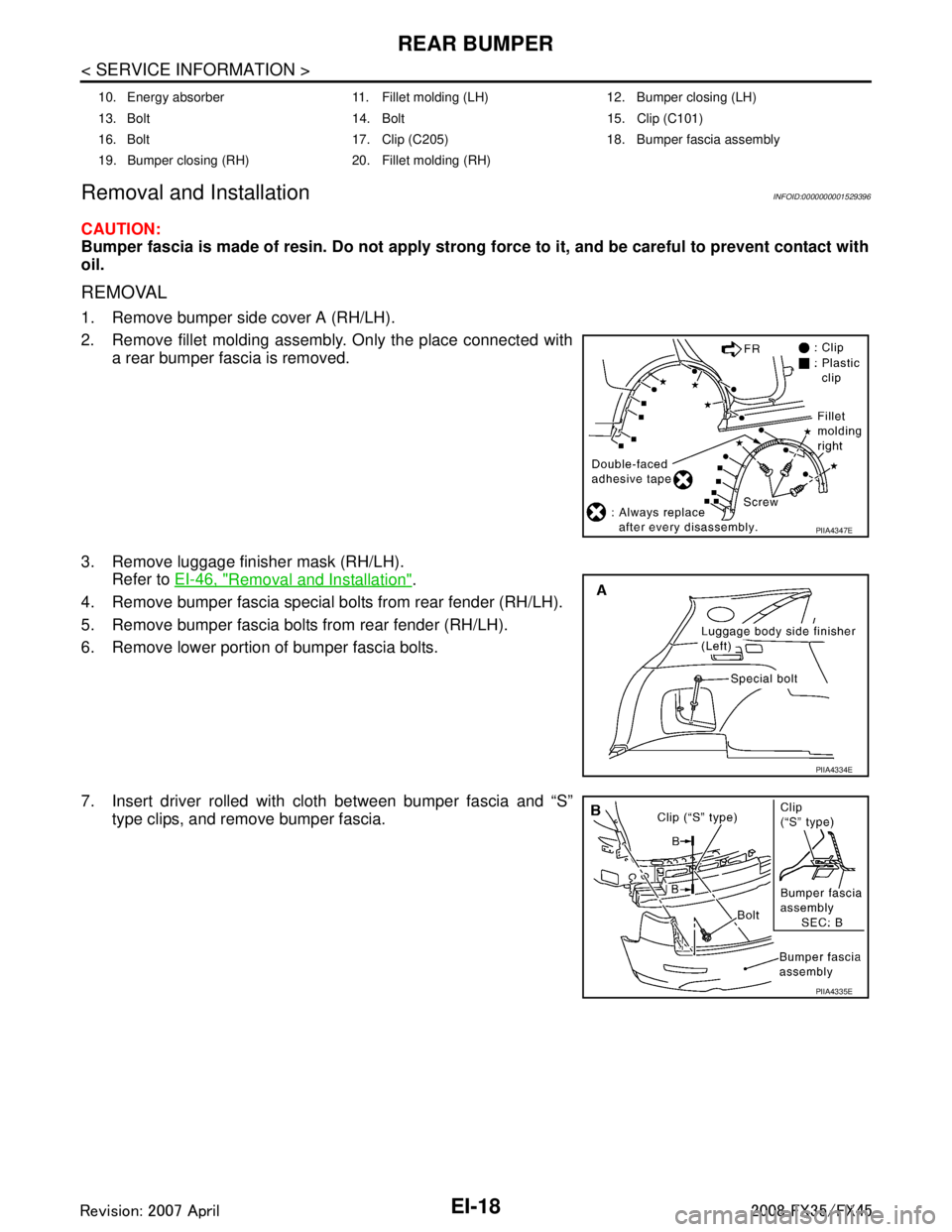
REMOVAL
1. Remove bumper side cover A (RH/LH).
2. Remove fillet molding assembly. Only the place connected with a rear bumper fascia is removed.
3. Remove luggage finisher mask (RH/LH). Refer to EI-46, "
Removal and Installation".
4. Remove bumper fascia special bolts from rear fender (RH/LH).
5. Remove bumper fascia bolts from rear fender (RH/LH).
6. Remove lower portion of bumper fascia bolts.
7. Insert driver rolled with cloth between bumper fascia and “S” type clips, and remove bumper fascia.
10. Energy absorber 11. Fillet molding (LH) 12. Bumper closing (LH)
13. Bolt 14. Bolt 15. Clip (C101)
16. Bolt 17. Clip (C205) 18. Bumper fascia assembly
19. Bumper closing (RH) 20. Fillet molding (RH)
PIIA4347E
PIIA4334E
PIIA4335E
3AA93ABC3ACD3AC03ACA3AC03AC63AC53A913A773A893A873A873A8E3A773A983AC73AC93AC03AC3
3A893A873A873A8F3A773A9D3AAF3A8A3A8C3A863A9D3AAF3A8B3A8C
Page 2456 of 3924

REAR BUMPEREI-19
< SERVICE INFORMATION >
C
DE
F
G H
J
K L
M A
B
EI
N
O P
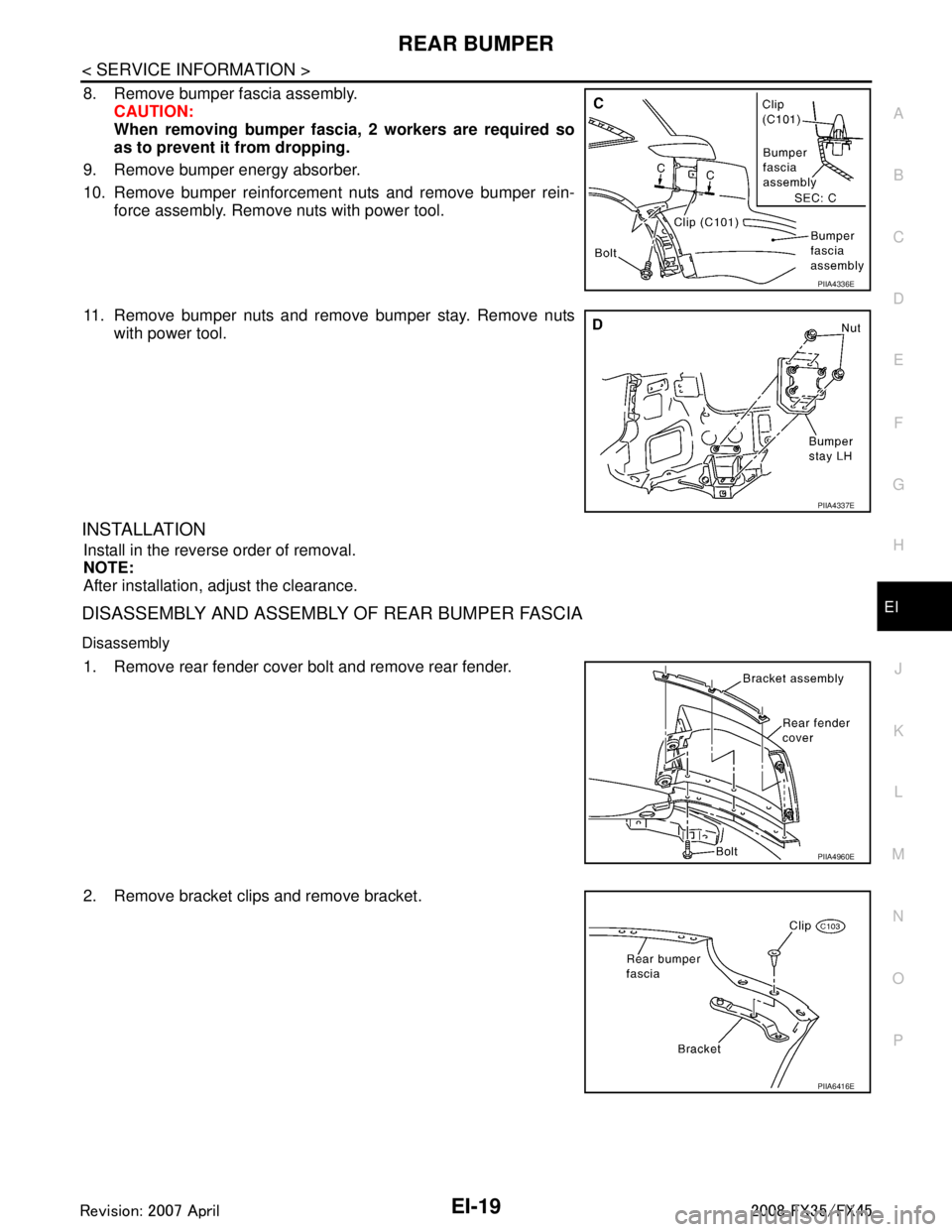
8. Remove bumper fascia assembly. CAUTION:
When removing bumper fasci a, 2 workers are required so
as to prevent it from dropping.
9. Remove bumper energy absorber.
10. Remove bumper reinforcement nuts and remove bumper rein- force assembly. Remove nuts with power tool.
11. Remove bumper nuts and remove bumper stay. Remove nuts with power tool.
INSTALLATION
Install in the reverse order of removal.
NOTE:
After installation, adjust the clearance.
DISASSEMBLY AND ASSEMBLY OF REAR BUMPER FASCIA
Disassembly
1. Remove rear fender cover bolt and remove rear fender.
2. Remove bracket clips and remove bracket.
PIIA4336E
PIIA4337E
PIIA4960E
PIIA6416E
3AA93ABC3ACD3AC03ACA3AC03AC63AC53A913A773A893A873A873A8E3A773A983AC73AC93AC03AC3
3A893A873A873A8F3A773A9D3AAF3A8A3A8C3A863A9D3AAF3A8B3A8C
Page 2530 of 3924
![INFINITI FX35 2008 Service Manual
EM-46
< SERVICE INFORMATION >[VQ35DE]
FUEL INJECTOR AND FUEL TUBE
4. Remove fuel feed hose (wit
h damper) from fuel sub-tube.
NOTE:
There is no fuel return route.
CAUTION:
While hoses are disconnec INFINITI FX35 2008 Service Manual
EM-46
< SERVICE INFORMATION >[VQ35DE]
FUEL INJECTOR AND FUEL TUBE
4. Remove fuel feed hose (wit
h damper) from fuel sub-tube.
NOTE:
There is no fuel return route.
CAUTION:
While hoses are disconnec](/manual-img/42/57017/w960_57017-2529.png)
EM-46
< SERVICE INFORMATION >[VQ35DE]
FUEL INJECTOR AND FUEL TUBE
4. Remove fuel feed hose (wit
h damper) from fuel sub-tube.
NOTE:
There is no fuel return route.
CAUTION:
While hoses are disconnected, plug them to prevent fuel
from draining.
Do not separate damper and hose.
5. When separating fuel feed hose (with damper) and centralized under-floor piping connection, disconnect
quick connector as the following:
a. Remove quick connector cap from quick connector connection on right member side.
b. Disconnect fuel feed hose (with damper) from bracket hose clamp.
c. Disconnect quick connector from centralized under-floor piping as follows: CAUTION:
Disconnect quick connector by using quick conn ector release [SST: — (J-45488)], not by picking
out retainer tabs.
i. With the sleeve side of quick connector release facing quick connector, install quick connector release
onto centralized under-floor piping.
ii. Insert quick connector release into quick connector until sleeve contacts and goes no further. Hold quick connector release on
that position.
CAUTION:
Inserting quick connector re lease hard will not disconnect
quick connector. Hold qui ck connector release where it
contacts and goes no further.
iii. Draw and pull out quick connector straight from centralized under-floor piping.
CAUTION:
Pull quick connector holding “A” position as shown in thefigure.
Do not pull with lateral force applied. O-ring inside quick connector may be damaged.
Prepare container and cloth beforehand as fuel will leak out.
Avoid fire and sparks.
Keep parts away from heat source. Especially, be careful when welding is performed around
them.
Do not expose parts to battery electrolyte or other acids.
Do not bend or twist connection between quick connector and fuel feed hose (with damper) dur-
ing installation/removal.
KBIA1293E
PBIC2083E
PBIC1898E
3AA93ABC3ACD3AC03ACA3AC03AC63AC53A913A773A893A873A873A8E3A773A983AC73AC93AC03AC3
3A893A873A873A8F3A773A9D3AAF3A8A3A8C3A863A9D3AAF3A8B3A8C
Page 2590 of 3924
![INFINITI FX35 2008 Service Manual
EM-106
< SERVICE INFORMATION >[VQ35DE]
CYLINDER HEAD
6. Remove valve oil seal using the valve oil seal puller (SST).
7. If valve seat must be replaced, refer to
EM-107, "
Inspection After Disassembl INFINITI FX35 2008 Service Manual
EM-106
< SERVICE INFORMATION >[VQ35DE]
CYLINDER HEAD
6. Remove valve oil seal using the valve oil seal puller (SST).
7. If valve seat must be replaced, refer to
EM-107, "
Inspection After Disassembl](/manual-img/42/57017/w960_57017-2589.png)
EM-106
< SERVICE INFORMATION >[VQ35DE]
CYLINDER HEAD
6. Remove valve oil seal using the valve oil seal puller (SST).
7. If valve seat must be replaced, refer to
EM-107, "
Inspection After Disassembly".
8. If valve guide must be replaced, refer to EM-107, "
Inspection After Disassembly".
9. Remove spark plug tube, as necessary. Using a pliers, pull spark plug tube out of cylinder head.
CAUTION:
Take care not to damage cylinder head.
Once removed, spark plug tube will be deformed and cannot be reused. Do not remove it unless
absolutely necessary.
ASSEMBLY
1. When valve guide is removed, install it. Refer to EM-107, "Inspection After Disassembly".
2. When valve seat is removed, install it. Refer to EM-107, "
Inspection After Disassembly".
3. Install new valve oil seals as follows:
a. Apply new engine oil on valve oil seal joint and seal lip.
b. Install with the valve oil seal drift (SST) to match dimension in the figure.
4. Install valve spring seat.
5. Install valve. Larger diameter valves are for intake side.NOTE:
Larger diameter valves are for intake side.
6. Install valve spring (uneven pitch type). Install narrow pitch end (paint mark) to cylinder head side(valve spring seat side).
Intake side and exhaust side valve springs are different. Install
them referring to the following paint mark collar.
7. Install valve spring retainer.
PBIC0884E
Height “H” (Without valve spring seat installed) Intake and exhaust : 14.3 - 14.9 mm (0.563 - 0.587 in)
PBIC2769E
Paint mark collarIntake and Exhaust : Blue
SEM085D
3AA93ABC3ACD3AC03ACA3AC03AC63AC53A913A773A893A873A873A8E3A773A983AC73AC93AC03AC3
3A893A873A873A8F3A773A9D3AAF3A8A3A8C3A863A9D3AAF3A8B3A8C