2008 INFINITI FX35 ABS
[x] Cancel search: ABSPage 2675 of 3924
![INFINITI FX35 2008 Service Manual
FUEL INJECTOR AND FUEL TUBEEM-191
< SERVICE INFORMATION > [VK45DE]
C
D
E
F
G H
I
J
K L
M A
EM
NP
O
3. Disconnect fuel feed hose on engine side as follows: (Perform
same procedure for the side of cent INFINITI FX35 2008 Service Manual
FUEL INJECTOR AND FUEL TUBEEM-191
< SERVICE INFORMATION > [VK45DE]
C
D
E
F
G H
I
J
K L
M A
EM
NP
O
3. Disconnect fuel feed hose on engine side as follows: (Perform
same procedure for the side of cent](/manual-img/42/57017/w960_57017-2674.png)
FUEL INJECTOR AND FUEL TUBEEM-191
< SERVICE INFORMATION > [VK45DE]
C
D
E
F
G H
I
J
K L
M A
EM
NP
O
3. Disconnect fuel feed hose on engine side as follows: (Perform
same procedure for the side of centralized under-floor piping as
well.)
a. Remove quick connector cap from quick connector connection.
b. Disconnect quick connector from fuel feed damper as follows:
CAUTION:
Disconnect quick connector by using quick connector release [S ST: J-45488], not by picking out
retainer tabs (centralized under-floor piping side).
i. With the sleeve side of quick connector release facing to quick connecto\
r, install quick connector release onto fuel tube.
ii. Insert quick connector releas e into quick connector until sleeve
contacts and goes no further. Hold quick connector release on
that position.
CAUTION:
Inserting quick connector re lease hard will not disconnect
quick connector. Hold qui ck connector release where it
contacts and goes no further.
iii. Draw and pull out quick connector straight from fuel feed damper.
CAUTION:
Pull quick connector holding “A” position as shown in thefigure.
Do not pull with lateral force applied. O-ring inside quick connector may be damaged.
Prepare container and cloth be forehand as fuel will leak out.
Avoid fire and sparks.
Keep parts away from heat source. Especially, be careful when welding is performed around
them.
Do not expose parts to battery electrolyte or other acids.
Do not bend or twist connection between quick co nnector and fuel feed hose during installation/
removal.
PBIC4552E
SBIA0354E
KBIA0702E
3AA93ABC3ACD3AC03ACA3AC03AC63AC53A913A773A893A873A873A8E3A773A983AC73AC93AC03AC3
3A893A873A873A8F3A773A9D3AAF3A8A3A8C3A863A9D3AAF3A8B3A8C
Page 2678 of 3924
![INFINITI FX35 2008 Service Manual
EM-194
< SERVICE INFORMATION >[VK45DE]
FUEL INJECTOR AND FUEL TUBE
Tighten mounting bolts in two steps in numerical order as
shown in the figure.
6. Connect fuel feed hose on engine side as follows INFINITI FX35 2008 Service Manual
EM-194
< SERVICE INFORMATION >[VK45DE]
FUEL INJECTOR AND FUEL TUBE
Tighten mounting bolts in two steps in numerical order as
shown in the figure.
6. Connect fuel feed hose on engine side as follows](/manual-img/42/57017/w960_57017-2677.png)
EM-194
< SERVICE INFORMATION >[VK45DE]
FUEL INJECTOR AND FUEL TUBE
Tighten mounting bolts in two steps in numerical order as
shown in the figure.
6. Connect fuel feed hose on engine side as follows: (Unless otherwise indicated, the installation to the engine side and centralized under-floor piping side is exactly alike.)
a. Make sure no foreign substances are deposited in and around fuel tube and quick connector, and no dam- age on them.
b. Thinly apply new engine oil around fuel tube from tip end to spool end.
c. Align center to insert quick connector straightly into fuel tube. Engine side:
Insert fuel tube into quick connector until top spool is com-
pletely inside quick connector, and 2nd level spool exposes
right below quick connector.
CAUTION:
Hold “A” position as shown in the figure when inserting
fuel tube into quick connector.
Carefully align center to avoid inclined insertion to pre-
vent damage to O-ring inside quick connector.
Insert until you hear a “click” sound and actually feel the
engagement.
To avoid misidentification of engagement with a si milar sound, be sure to perform the next step.
Centralized under-floor piping side:
Visually confirm that the two retainer tabs are connected to the connector.
CAUTION:
Carefully align center to avoid inclined insertion to prevent dama ge to O-ring inside quick con-
nector.
Insert until you hear a “click” soun d and actually feel the engagement.
To avoid misidentification of engagement with a si milar sound, be sure to perform the next step.
d. Pull quick connector by hand holding position. Make su re it is completely engaged (connected) so that it
does not come out from fuel tube.
e. Install quick connector cap on quick connector connection. CAUTION:
If cap cannot be installed smoothly, quick connector may
have not been installed corr ectly. Check connection again.
f. Install fuel feed hose to hose clamps.
7. Install in the reverse order of removal after this step.
INSPECTION AFTER INSTALLATION
Check on Fuel Leakage
1. Turn ignition switch “ON” (with engine stopped). With fuel pressure applied to fuel piping, check for fuel leakage at connection points.
NOTE:
Use mirrors for checking at points out of clear sight.
A : Right bank
B : Left bank
: Engine front
1st step : 10.1 N·m (1.0 kg-m, 7 ft-lb)
2nd step : 23.5 N·m (2.4 kg-m, 17 ft-lb)
PBIC3303E
KBIA0272E
SBIA0354E
3AA93ABC3ACD3AC03ACA3AC03AC63AC53A913A773A893A873A873A8E3A773A983AC73AC93AC03AC3
3A893A873A873A8F3A773A9D3AAF3A8A3A8C3A863A9D3AAF3A8B3A8C
Page 2715 of 3924
![INFINITI FX35 2008 Service Manual
CYLINDER HEADEM-231
< SERVICE INFORMATION > [VK45DE]
C
D
E
F
G H
I
J
K L
M A
EM
NP
O
6. Remove valve oil seal with valve oil seal puller (SST).
7. If valve seat must be replaced, refer to
EM-232, "
INFINITI FX35 2008 Service Manual
CYLINDER HEADEM-231
< SERVICE INFORMATION > [VK45DE]
C
D
E
F
G H
I
J
K L
M A
EM
NP
O
6. Remove valve oil seal with valve oil seal puller (SST).
7. If valve seat must be replaced, refer to
EM-232, "](/manual-img/42/57017/w960_57017-2714.png)
CYLINDER HEADEM-231
< SERVICE INFORMATION > [VK45DE]
C
D
E
F
G H
I
J
K L
M A
EM
NP
O
6. Remove valve oil seal with valve oil seal puller (SST).
7. If valve seat must be replaced, refer to
EM-232, "
Inspection After Disassembly".
8. If valve guide must be replaced, refer to EM-232, "
Inspection After Disassembly".
9. Remove spark plug tube, as necessary. Using pair of pliers, pull spark plug tube out of cylinder head.
CAUTION:
Take care not to damage cylinder head.
Once removed, spark plug tube will be deforme d and cannot be reused. Do not remove it unless
absolutely necessary.
ASSEMBLY
1. When valve guide is removed, install it. Refer to EM-232, "Inspection After Disassembly".
2. When valve seat is removed, install it. Refer to EM-232, "
Inspection After Disassembly".
3. Install new valve oil seal as follows:
a. Apply new engine oil on valve oil seal joint and seal lip.
b. Install with valve oil seal drift (SST) to match dimension in the figure.
4. Install valve. Install in the original position.NOTE:
Larger diameter valves are for intake side.
5. Install valve spring (with valve spring seat). Install smaller pitch (valve spring seat side) to cylinder head
side.
6. Install valve spring retainer.
7. Install valve collet.
PBIC0072E
PBIC0073E
PBIC0074E
3AA93ABC3ACD3AC03ACA3AC03AC63AC53A913A773A893A873A873A8E3A773A983AC73AC93AC03AC3
3A893A873A873A8F3A773A9D3AAF3A8A3A8C3A863A9D3AAF3A8B3A8C
Page 2837 of 3924
FUEL LEVEL SENSOR UNIT, FUEL FILTER AND FUEL PUMP ASSEMBLY
FL-5
< SERVICE INFORMATION >
C
D E
F
G H
I
J
K L
M A
FL
NP
O
2. Release the fuel pressure from the fuel lines. Refer to
EC-87, "Fuel Pressure Check" (VQ35DE) or EC-
665, "Fuel Pressure Check" (VK45DE).
3. Open fuel filler lid.
4. Open filler cap and release the pressure inside fuel tank.
5. Remove rear seat cushion. Refer to SE-95, "
Removal and Installation".
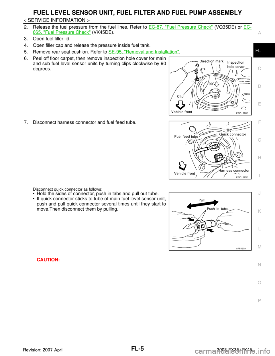
6. Peel off floor carpet, then remove inspection hole cover for main and sub fuel level sensor units by turning clips clockwise by 90
degrees.
7. Disconnect harness connector and fuel feed tube.
Disconnect quick connector as follows: Hold the sides of connector, push in tabs and pull out tube.
If quick connector sticks to tube of main fuel level sensor unit, push and pull quick connector several times until they start to
move.Then disconnect them by pulling.
CAUTION:
PBIC1576E
PBIC1577E
SFE562A
3AA93ABC3ACD3AC03ACA3AC03AC63AC53A913A773A893A873A873A8E3A773A983AC73AC93AC03AC3
3A893A873A873A8F3A773A9D3AAF3A8A3A8C3A863A9D3AAF3A8B3A8C
Page 2838 of 3924
FL-6
< SERVICE INFORMATION >
FUEL LEVEL SENSOR UNIT, FUEL FILTER AND FUEL PUMP ASSEMBLY
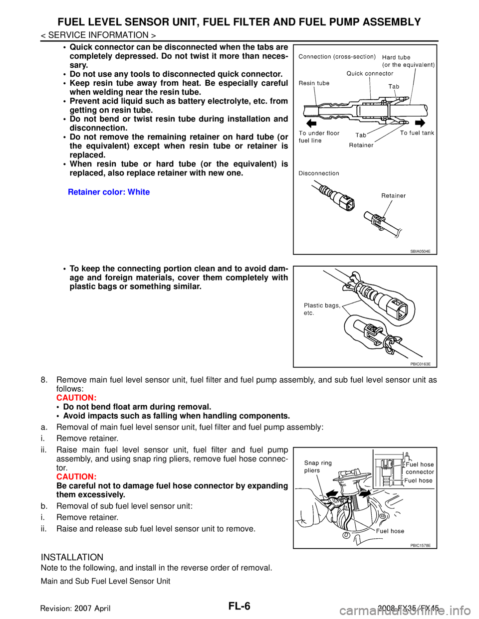
Quick connector can be disconnected when the tabs are
completely depressed. Do not twist it more than neces-
sary.
Do not use any tools to disconnected quick connector.
Keep resin tube away from heat. Be especially careful when welding near the resin tube.
Prevent acid liquid such as battery electrolyte, etc. from getting on resin tube.
Do not bend or twist resin tube during installation and
disconnection.
Do not remove the remaining retainer on hard tube (or the equivalent) except when resin tube or retainer is
replaced.
When resin tube or hard tube (or the equivalent) is replaced, also replace retainer with new one.
To keep the connecting porti on clean and to avoid dam-
age and foreign materials, cover them completely with
plastic bags or something similar.
8. Remove main fuel level sensor unit, fuel filter and fuel pump assembly, and sub fuel level sensor unit as
follows:
CAUTION:
Do not bend float arm during removal.
Avoid impacts such as fallin g when handling components.
a. Removal of main fuel level sensor uni t, fuel filter and fuel pump assembly:
i. Remove retainer.
ii. Raise main fuel level sensor unit, fuel filter and fuel pump assembly, and using snap ring pliers, remove fuel hose connec-
tor.
CAUTION:
Be careful not to damage fu el hose connector by expanding
them excessively.
b. Removal of sub fuel level sensor unit:
i. Remove retainer.
ii. Raise and release sub fuel level sensor unit to remove.
INSTALLATION
Note to the following, and install in the reverse order of removal.
Main and Sub Fuel Level Sensor Unit
Retainer color: White
SBIA0504E
PBIC0163E
PBIC1578E
3AA93ABC3ACD3AC03ACA3AC03AC63AC53A913A773A893A873A873A8E3A773A983AC73AC93AC03AC3
3A893A873A873A8F3A773A9D3AAF3A8A3A8C3A863A9D3AAF3A8B3A8C
Page 2839 of 3924
FUEL LEVEL SENSOR UNIT, FUEL FILTER AND FUEL PUMP ASSEMBLY
FL-7
< SERVICE INFORMATION >
C
D E
F
G H
I
J
K L
M A
FL
NP
O
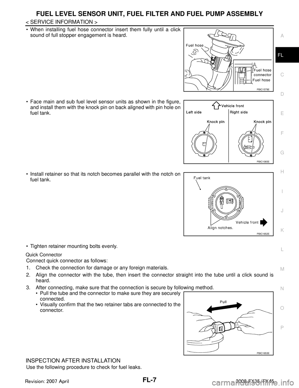
When installing fuel hose connector insert them fully until a click
sound of full stopper engagement is heard.
Face main and sub fuel level sensor units as shown in the figure, and install them with the knock pin on back aligned with pin hole on
fuel tank.
Install retainer so that its notch becomes parallel with the notch on fuel tank.
Tighten retainer mounting bolts evenly.
Quick Connector
Connect quick connector as follows:
1. Check the connection for damage or any foreign materials.
2. Align the connector with the tube, then insert the connector straight into the tube until a click sound is
heard.
3. After connecting, make sure that the connection is secure by following method. Pull the tube and the connector to make sure they are securelyconnected.
Visually confirm that the two retainer tabs are connected to the
connector.
INSPECTION AFTER INSTALLATION
Use the following procedure to check for fuel leaks.
PBIC1579E
PBIC1065E
PBIC1652E
PBIC1653E
3AA93ABC3ACD3AC03ACA3AC03AC63AC53A913A773A893A873A873A8E3A773A983AC73AC93AC03AC3
3A893A873A873A8F3A773A9D3AAF3A8A3A8C3A863A9D3AAF3A8B3A8C
Page 2840 of 3924
FL-8
< SERVICE INFORMATION >
FUEL LEVEL SENSOR UNIT, FUEL FILTER AND FUEL PUMP ASSEMBLY
1. Turn ignition switch “ON” (with engine stopped), then check connections for leaks by applying fuel pres-
sure to fuel piping.
2. Start engine and let it idle and make sure there are no fuel leaks at the fuel system connections.
ComponentINFOID:0000000001327108
Disassembly and AssemblyINFOID:0000000001327109
CAUTION:
Sub fuel level sensor unit cannot be disassembled and should be replaced as a unit.
DISASSEMBLY
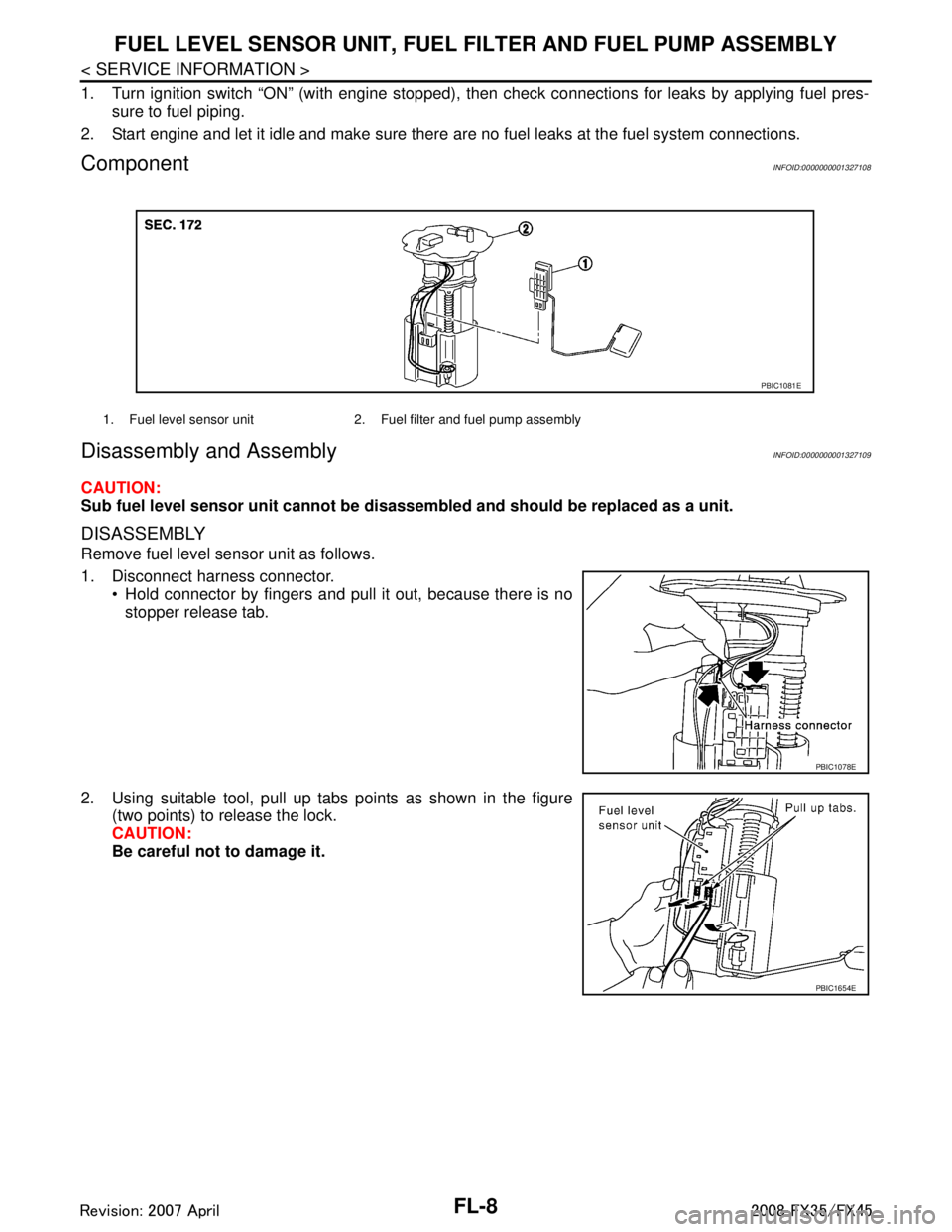
Remove fuel level sensor unit as follows.
1. Disconnect harness connector.
Hold connector by fingers and pull it out, because there is no
stopper release tab.
2. Using suitable tool, pull up tabs points as shown in the figure (two points) to release the lock.
CAUTION:
Be careful not to damage it.
1. Fuel level sensor unit 2. Fuel filter and fuel pump assembly
PBIC1081E
PBIC1078E
PBIC1654E
3AA93ABC3ACD3AC03ACA3AC03AC63AC53A913A773A893A873A873A8E3A773A983AC73AC93AC03AC3
3A893A873A873A8F3A773A9D3AAF3A8A3A8C3A863A9D3AAF3A8B3A8C
Page 2841 of 3924
FUEL LEVEL SENSOR UNIT, FUEL FILTER AND FUEL PUMP ASSEMBLY
FL-9
< SERVICE INFORMATION >
C
D E
F
G H
I
J
K L
M A
FL
NP
O
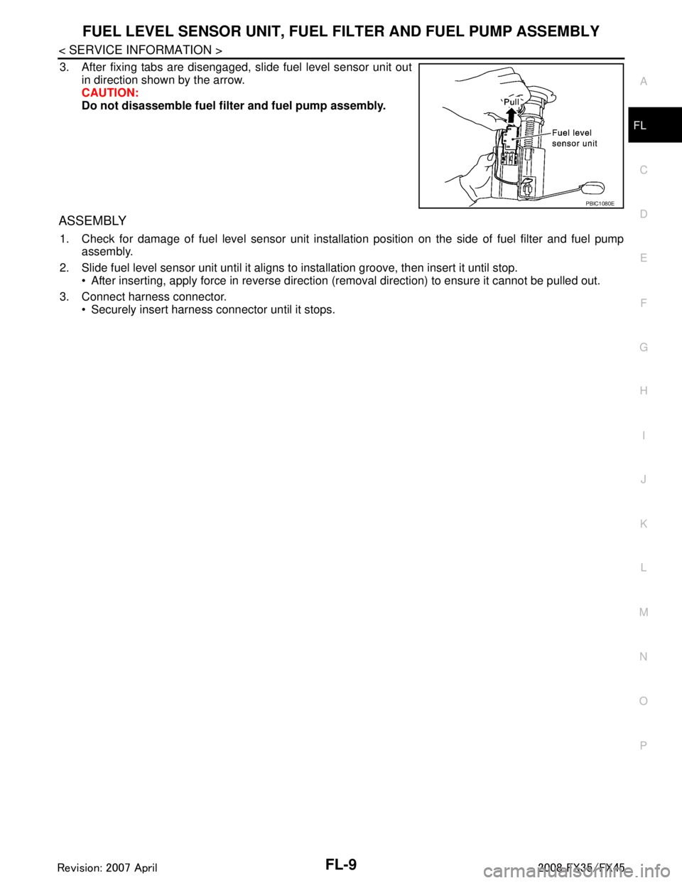
3. After fixing tabs are disengaged, slide fuel level sensor unit out
in direction shown by the arrow.
CAUTION:
Do not disassemble fuel filt er and fuel pump assembly.
ASSEMBLY
1. Check for damage of fuel level sensor unit installa tion position on the side of fuel filter and fuel pump
assembly.
2. Slide fuel level sensor unit until it aligns to installation groove, then insert it until stop. After inserting, apply force in reverse direction (removal direction) to ensure it cannot be pulled out.
3. Connect harness connector. Securely insert harness connector until it stops.
PBIC1080E
3AA93ABC3ACD3AC03ACA3AC03AC63AC53A913A773A893A873A873A8E3A773A983AC73AC93AC03AC3
3A893A873A873A8F3A773A9D3AAF3A8A3A8C3A863A9D3AAF3A8B3A8C