Page 1173 of 3924

A/T INDICATORDI-47
< SERVICE INFORMATION >
C
DE
F
G H
I
J
L
M A
B
DI
N
O P
A/T INDICATOR
System DescriptionINFOID:0000000001328470
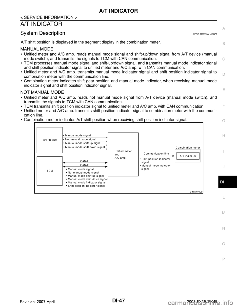
A/T shift position is displayed in the s egment display in the combination meter.
MANUAL MODE
Unified meter and A/C amp. reads manual mode signal and shift-up/down signal from A/T device (manual
mode switch), and transmits the signals to TCM with CAN communication.
TCM processes manual mode signal and shift-up/down signal, and transmits manual mode indicator signal and shift position indicator signal to unified meter and A/C amp. with CAN communication.
Unified meter and A/C amp. transmits manual mode indicator signal and shift position indicator signal to
combination meter with the communication line.
Combination meter indicates shift gear position and manual mode indicator, when receiving manual mode
indicator signal and shift position indicator signal.
NOT MANUAL MODE
Unified meter and A/C amp. reads not manual mode signal from A/T device (manual mode switch), and
transmits the signals to TCM with CAN communication.
TCM transmits shift position indicator signal to unified meter and A/C amp. with CAN communication.
Unified meter and A/C amp. transmits shift position indicator signal to combination meter with the communi- cation line.
Combination meter indicates A/T shift position when receiving shift position indicator signal.
JPNIA0373GB
3AA93ABC3ACD3AC03ACA3AC03AC63AC53A913A773A893A873A873A8E3A773A983AC73AC93AC03AC3
3A893A873A873A8F3A773A9D3AAF3A8A3A8C3A863A9D3AAF3A8B3A8C
Page 1174 of 3924
DI-48
< SERVICE INFORMATION >
A/T INDICATOR
Wiring Diagram - AT/IND -
INFOID:0000000001328471
TKWM4354E
3AA93ABC3ACD3AC03ACA3AC03AC63AC53A913A773A893A873A873A8E3A773A983AC73AC93AC03AC3
3A893A873A873A8F3A773A9D3AAF3A8A3A8C3A863A9D3AAF3A8B3A8C
Page 1175 of 3924
A/T INDICATORDI-49
< SERVICE INFORMATION >
C
DE
F
G H
I
J
L
M A
B
DI
N
O P
A/T Indicator Is MalfunctionINFOID:0000000001328472
1.CHECK SEGMENTS OF A/T INDICATOR
TKWM4355E
3AA93ABC3ACD3AC03ACA3AC03AC63AC53A913A773A893A873A873A8E3A773A983AC73AC93AC03AC3
3A893A873A873A8F3A773A9D3AAF3A8A3A8C3A863A9D3AAF3A8B3A8C
Page 1176 of 3924

DI-50
< SERVICE INFORMATION >
A/T INDICATOR
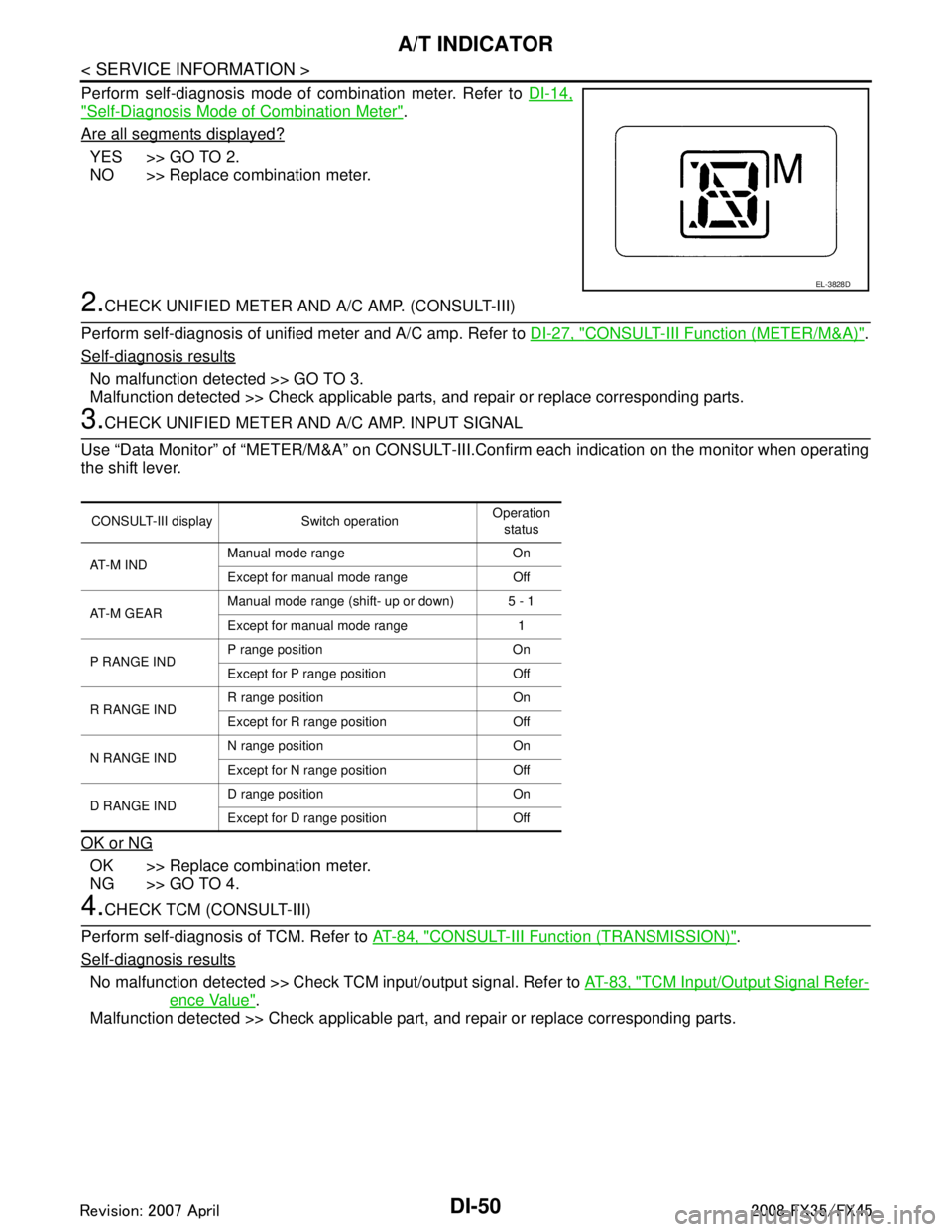
Perform self-diagnosis mode of combination meter. Refer to DI-14,
"Self-Diagnosis Mode of Combination Meter".
Are all segments displayed?
YES >> GO TO 2.
NO >> Replace combination meter.
2.CHECK UNIFIED METER AND A/C AMP. (CONSULT-III)
Perform self-diagnosis of unified meter and A/C amp. Refer to DI-27, "
CONSULT-III Function (METER/M&A)".
Self-diagnosis results
No malfunction detected >> GO TO 3.
Malfunction detected >> Check applicable parts, and repair or replace corresponding parts.
3.CHECK UNIFIED METER AND A/C AMP. INPUT SIGNAL
Use “Data Monitor” of “METER/M&A” on CONSULT-III. Confirm each indication on the monitor when operating
the shift lever.
OK or NG
OK >> Replace combination meter.
NG >> GO TO 4.
4.CHECK TCM (CONSULT-III)
Perform self-diagnosis of TCM. Refer to AT-84, "
CONSULT-III Function (TRANSMISSION)".
Self-diagnosis results
No malfunction detected >> Check TCM input/output signal. Refer to AT-83, "TCM Input/Output Signal Refer-
ence Value".
Malfunction detected >> Check applicable part, and repair or replace corresponding parts.
EL-3828D
CONSULT-III display Switch operation Operation
status
AT - M I N D Manual mode range On
Except for manual mode range Off
AT-M GEAR Manual mode range (shift- up or down) 5 - 1
Except for manual mode range 1
P RANGE IND P range position On
Except for P range position Off
R RANGE IND R range position On
Except for R range position Off
N RANGE IND N range position On
Except for N range position Off
D RANGE IND D range position On
Except for D range position Off
3AA93ABC3ACD3AC03ACA3AC03AC63AC53A913A773A893A873A873A8E3A773A983AC73AC93AC03AC3
3A893A873A873A8F3A773A9D3AAF3A8A3A8C3A863A9D3AAF3A8B3A8C
Page 1177 of 3924

WARNING CHIMEDI-51
< SERVICE INFORMATION >
C
DE
F
G H
I
J
L
M A
B
DI
N
O P
WARNING CHIME
System DescriptionINFOID:0000000001328473
Buzzer for warning chime system is installed in the combination meter.
The buzzer sounds when the combination meter receives buzzer output signal from each unit through uni- fied meter and A/C amp.
POWER SUPPLY AND CIRCUIT
Power is supplied at all times
through 50A fusible link (letter M, located in the fuse and fusible link block)
to BCM terminal 55,
through 15A fuse [No. 22, located in the fuse block (J/B)]
to key switch and ignition knob switch terminal 3 (with Intelligent Key), and
to key switch terminal 2 (without Intelligent Key), and
to BCM terminal 42,
through 10A fuse [No. 38, located in the fuse and fusible link block (with Intelligent Key)]
to key switch and ignition knob switch terminal 1,
through 10A fuse [No. 19, located in the fuse block (J/B)]
to unified meter and A/C amp. terminal 21, and
to combination meter terminal 8.
When ignition switch is in ON or START position, power is supplied
through 15A fuse [No. 1, located in the fuse block (J/B)]
to BCM terminal 38,
through 10A fuse [No. 12, located in the fuse block (J/B)]
to unified meter and A/C amp. terminal 22,
through 10A fuse [No. 14, located in the fuse block (J/B)]
to combination meter terminal 7.
Ground is supplied
to BCM terminals 49 and 52,
to unified meter and A/C amp. terminals 29 and 30, and
to combination meter terminals 5, 6 and 15
through grounds M35, M45 and M85.
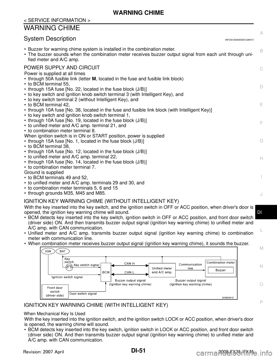
IGNITION KEY WARNING CHIME (WITHOUT INTELLIGENT KEY)
With the key inserted into the key switch, and the igniti on switch in OFF or ACC position, when driver's door is
opened, the ignition key warning chime will sound.
BCM detects key inserted into the key switch, igniti on switch in OFF or ACC position, and front door switch
(driver side) ON. And then transmits buzzer output signal (ignition key warning chime) to unified meter and
A/C amp. with CAN communication.
Unified meter and A/C amp. transmits buzzer output signal (ignition key warning chime) to combination
meter with communication line.
When combination meter receives buzzer output signal (ignition key warning chime), it sounds the buzzer.
IGNITION KEY WARNING CHIME (WITH INTELLIGENT KEY)
When Mechanical Key Is Used
With the key inserted into the ignition switch, and the i gnition switch LOCK or ACC position, when driver's door
is opened, the warning chime will sound.
BCM detects key inserted into the key switch, ignition switch in LOCK or ACC position, and front door switch
(driver side) ON. And then transmits buzzer output signal (ignition key warning chime) to unified meter and
A/C amp. with CAN communication.
SKIB6481E
3AA93ABC3ACD3AC03ACA3AC03AC63AC53A913A773A893A873A873A8E3A773A983AC73AC93AC03AC3
3A893A873A873A8F3A773A9D3AAF3A8A3A8C3A863A9D3AAF3A8B3A8C
Page 1178 of 3924

DI-52
< SERVICE INFORMATION >
WARNING CHIME
Unified meter and A/C amp. transmits buzzer output signal (ignition key warning chime) to combinationmeter with communication line.
When combination meter receives buzzer output signal (ignition key warning chime), it sounds the buzzer.
When Intelligent Key Is Carried With The Driver
Refer to BL-78, "System Description".
LIGHT WARNING CHIME
With ignition switch in LOCK or ACC position, driver 's door is opened, and lighting switch in 1ST or 2ND posi-
tion, the light warning chime will sound.
BCM detects ignition switch in LOCK or ACC position, front door switch (driver side) ON, and lighting switch
in 1ST or 2ND position. And then transmits buzzer output signal (light warning chime) to unified meter and A/
C amp. with CAN communication.
Unified meter and A/C amp. transmits buzzer output signal (light warning chime) to combination meter with
communication line.
When combination meter receives buzzer output signal (light warning chime), it sounds the buzzer.
NOTE:
For further details of combination switch, refer to BCS-4, "
System Description".
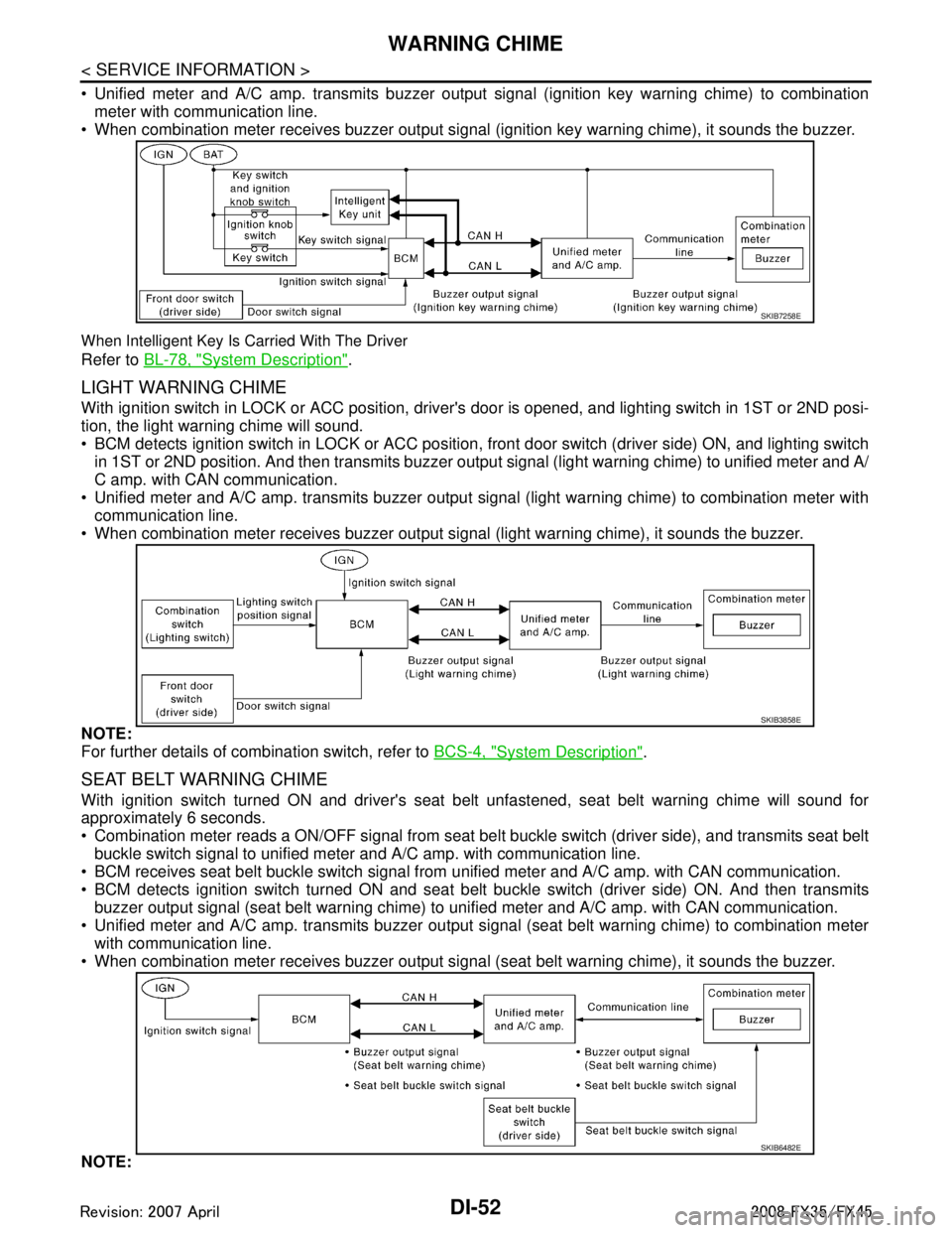
SEAT BELT WARNING CHIME
With ignition switch turned ON and driver's seat belt unfastened, seat belt warning chime will sound for
approximately 6 seconds.
Combination meter reads a ON/OFF signal from seat bel t buckle switch (driver side), and transmits seat belt
buckle switch signal to unified meter and A/C amp. with communication line.
BCM receives seat belt buckle switch signal from unified meter and A/C amp. with CAN communication.
BCM detects ignition switch turned ON and seat bel t buckle switch (driver side) ON. And then transmits
buzzer output signal (seat belt warning chime) to unified meter and A/C amp. with CAN communication.
Unified meter and A/C amp. transmits buzzer output signal (seat belt warning chime) to combination meter with communication line.
When combination meter receives buzzer output signal (seat belt warning chime), it sounds the buzzer.
NOTE:
SKIB7258E
SKIB3858E
SKIB6482E
3AA93ABC3ACD3AC03ACA3AC03AC63AC53A913A773A893A873A873A8E3A773A983AC73AC93AC03AC3
3A893A873A873A8F3A773A9D3AAF3A8A3A8C3A863A9D3AAF3A8B3A8C
Page 1179 of 3924
WARNING CHIMEDI-53
< SERVICE INFORMATION >
C
DE
F
G H
I
J
L
M A
B
DI
N
O P
When ignition key warning chime, light warning chime, and seat belt warning chime should be performed at
the same time, the priorities for each chime are the following.
1. Seat belt warning chime
2. Light warning chime
3. Ignition key warning chime
Component Parts and Har ness Connector LocationINFOID:0000000001328474
SKIB8485E
3AA93ABC3ACD3AC03ACA3AC03AC63AC53A913A773A893A873A873A8E3A773A983AC73AC93AC03AC3
3A893A873A873A8F3A773A9D3AAF3A8A3A8C3A863A9D3AAF3A8B3A8C
Page 1180 of 3924
DI-54
< SERVICE INFORMATION >
WARNING CHIME
Schematic
INFOID:0000000001328475
TKWM4356E
3AA93ABC3ACD3AC03ACA3AC03AC63AC53A913A773A893A873A873A8E3A773A983AC73AC93AC03AC3
3A893A873A873A8F3A773A9D3AAF3A8A3A8C3A863A9D3AAF3A8B3A8C