Page 1157 of 3924

UNIFIED METER AND A/C AMPDI-31
< SERVICE INFORMATION >
C
DE
F
G H
I
J
L
M A
B
DI
N
O P
NO >> GO TO 6.
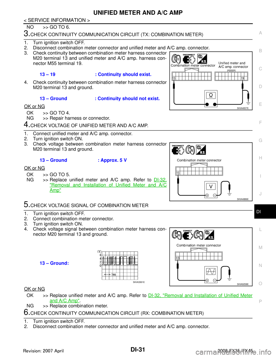
3.CHECK CONTINUITY COMM UNICATION CIRCUIT (TX: COMBINATION METER)
1. Turn ignition switch OFF.
2. Disconnect combination meter connector and unified meter and A/C amp. connector.
3. Check continuity between combination meter harness connector M20 terminal 13 and unified meter and A/C amp. harness con-
nector M55 terminal 19.
4. Check continuity between combination meter harness connector M20 terminal 13 and ground.
OK or NG
OK >> GO TO 4.
NG >> Repair harness or connector.
4.CHECK VOLTAGE OF UNIFIED METER AND A/C AMP.
1. Connect unified meter and A/C amp. connector.
2. Turn ignition switch ON.
3. Check voltage between combination meter harness connector M20 terminal 13 and ground.
OK or NG
OK >> GO TO 5.
NG >> Replace unified meter and A/C amp. Refer to DI-32,
"Removal and Installation of Unified Meter and A/C
Amp"
5.CHECK VOLTAGE SIGNAL OF COMBINATION METER
1. Turn ignition switch OFF.
2. Connect combination meter connector.
3. Turn ignition switch ON.
4. Check voltage signal between combination meter harness con- nector M20 terminal 13 and ground.
OK or NG
OK >> Replace unified meter and A/C amp. Refer to DI-32, "Removal and Installation of Unified Meter
and A/C Amp".
NG >> Replace combination meter.
6.CHECK CONTINUITY COMM UNICATION CIRCUIT (RX: COMBINATION METER)
1. Turn ignition switch OFF.
2. Disconnect combination meter connector and unified meter and A/C amp. connector.
13 – 19 : Continuity should exist.
13 – Ground : Continuity should not exist.
SKIA4837E
13 – Ground : Approx. 5 V
SKIA4886E
13 – Ground:
SKIA9258ESKIA3361E
3AA93ABC3ACD3AC03ACA3AC03AC63AC53A913A773A893A873A873A8E3A773A983AC73AC93AC03AC3
3A893A873A873A8F3A773A9D3AAF3A8A3A8C3A863A9D3AAF3A8B3A8C
Page 1158 of 3924

DI-32
< SERVICE INFORMATION >
UNIFIED METER AND A/C AMP
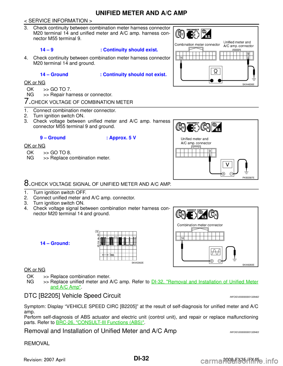
3. Check continuity between combination meter harness connectorM20 terminal 14 and unified meter and A/C amp. harness con-
nector M55 terminal 9.
4. Check continuity between combination meter harness connector M20 terminal 14 and ground.
OK or NG
OK >> GO TO 7.
NG >> Repair harness or connector.
7.CHECK VOLTAGE OF COMBINATION METER
1. Connect combination meter connector.
2. Turn ignition switch ON.
3. Check voltage between unified meter and A/C amp. harness connector M55 terminal 9 and ground.
OK or NG
OK >> GO TO 8.
NG >> Replace combination meter.
8.CHECK VOLTAGE SIGNAL OF UNIFIED METER AND A/C AMP.
1. Turn ignition switch OFF.
2. Connect unified meter and A/C amp. connector.
3. Turn ignition switch ON.
4. Check voltage signal between combination meter harness con- nector M20 terminal 14 and ground.
OK or NG
OK >> Replace combination meter.
NG >> Replace unified meter and A/C amp. Refer to DI-32, "
Removal and Installation of Unified Meter
and A/C Amp".
DTC [B2205] Vehicle Speed CircuitINFOID:0000000001328462
Symptom: Display “VEHICLE SPEED CIRC [B2205]” at the result of self-diagnosis for unified meter and A/C
amp.
Perform self-diagnosis of ABS actuator and electric unit (control unit), and repair or replace malfunctioning
parts. Refer to BRC-26, "
CONSULT-III Functions (ABS)".
Removal and Installation of Unified Meter and A/C AmpINFOID:0000000001328463
REMOVAL
14 – 9 : Continuity should exist.
14 – Ground : Continuity should not exist.
SKIA4836E
9 – Ground : Approx. 5 V
PKIB3587E
14 – Ground:
SKIA9260ESKIA3362E
3AA93ABC3ACD3AC03ACA3AC03AC63AC53A913A773A893A873A873A8E3A773A983AC73AC93AC03AC3
3A893A873A873A8F3A773A9D3AAF3A8A3A8C3A863A9D3AAF3A8B3A8C
Page 1159 of 3924
UNIFIED METER AND A/C AMPDI-33
< SERVICE INFORMATION >
C
DE
F
G H
I
J
L
M A
B
DI
N
O P
1. Remove the audio unit (1). Refer to AV-41, "Removal and Instal-
lation of Audio Unit".
2. Remove the screws (A).
3. Remove the screws (B) and remove the unified meter and A/C amp. (2).
INSTALLATION
Installation is the reverse order of removal.
NOTE:
Use appropriate screws for each, as screws for audio unit and display unit are different from that for unified
meter and A/C amp.
SKIB8483E
3AA93ABC3ACD3AC03ACA3AC03AC63AC53A913A773A893A873A873A8E3A773A983AC73AC93AC03AC3
3A893A873A873A8F3A773A9D3AAF3A8A3A8C3A863A9D3AAF3A8B3A8C
Page 1160 of 3924
DI-34
< SERVICE INFORMATION >
WARNING LAMPS
WARNING LAMPS
System DescriptionINFOID:0000000001328464
OIL PRESSURE WARNING LAMP
Oil pressure warning lamp turns ON when reducing engine oil pressure abnormally.
IPDM E/R reads oil pressure switch signal from oil pressure switch, and transmits the signal to unified meterand A/C amp. through BCM with CAN communication.
Unified meter and A/C amp. transmits oil pressure s witch signal to combination meter with communication
line.
Combination meter turns oil pressure warning lamp ON with received oil pressure switch signal.
PKIB7655E
3AA93ABC3ACD3AC03ACA3AC03AC63AC53A913A773A893A873A873A8E3A773A983AC73AC93AC03AC3
3A893A873A873A8F3A773A9D3AAF3A8A3A8C3A863A9D3AAF3A8B3A8C
Page 1161 of 3924
WARNING LAMPSDI-35
< SERVICE INFORMATION >
C
DE
F
G H
I
J
L
M A
B
DI
N
O P
SchematicINFOID:0000000001328465
TKWM4895E
3AA93ABC3ACD3AC03ACA3AC03AC63AC53A913A773A893A873A873A8E3A773A983AC73AC93AC03AC3
3A893A873A873A8F3A773A9D3AAF3A8A3A8C3A863A9D3AAF3A8B3A8C
Page 1162 of 3924
DI-36
< SERVICE INFORMATION >
WARNING LAMPS
Wiring Diagram - WARN -
INFOID:0000000001328466
TKWM4346E
3AA93ABC3ACD3AC03ACA3AC03AC63AC53A913A773A893A873A873A8E3A773A983AC73AC93AC03AC3
3A893A873A873A8F3A773A9D3AAF3A8A3A8C3A863A9D3AAF3A8B3A8C
Page 1163 of 3924
WARNING LAMPSDI-37
< SERVICE INFORMATION >
C
DE
F
G H
I
J
L
M A
B
DI
N
O P
TKWM4347E
3AA93ABC3ACD3AC03ACA3AC03AC63AC53A913A773A893A873A873A8E3A773A983AC73AC93AC03AC3
3A893A873A873A8F3A773A9D3AAF3A8A3A8C3A863A9D3AAF3A8B3A8C
Page 1164 of 3924
DI-38
< SERVICE INFORMATION >
WARNING LAMPS
TKWM4348E
3AA93ABC3ACD3AC03ACA3AC03AC63AC53A913A773A893A873A873A8E3A773A983AC73AC93AC03AC3
3A893A873A873A8F3A773A9D3AAF3A8A3A8C3A863A9D3AAF3A8B3A8C