2008 INFINITI FX35 ignition switch
[x] Cancel search: ignition switchPage 3100 of 3924
![INFINITI FX35 2008 Service Manual
LAN-80
< SERVICE INFORMATION >[CAN]
TROUBLE DIAGNOSIS
2.CHECK HARNESS FOR OPEN CIRCUIT
1. Disconnect the connector of driver seat control unit.
2. Check the resistance between the driver seat contro INFINITI FX35 2008 Service Manual
LAN-80
< SERVICE INFORMATION >[CAN]
TROUBLE DIAGNOSIS
2.CHECK HARNESS FOR OPEN CIRCUIT
1. Disconnect the connector of driver seat control unit.
2. Check the resistance between the driver seat contro](/manual-img/42/57017/w960_57017-3099.png)
LAN-80
< SERVICE INFORMATION >[CAN]
TROUBLE DIAGNOSIS
2.CHECK HARNESS FOR OPEN CIRCUIT
1. Disconnect the connector of driver seat control unit.
2. Check the resistance between the driver seat control unit harness connector terminals.
OK or NG
OK >> GO TO 3.
NG >> Repair the driver seat control unit branch line.
3.CHECK POWER SUPPLY AND GROUND CIRCUIT
Check the power supply and the ground circuit of the driver seat control unit. Refer to SE-18, "
Schematic".
OK or NG
OK >> Present error: Replace the driver seat control unit. Refer to SE-16, "Component Parts and Har-
ness Connector Location".
Past error: Error was detected in t he driver seat control unit branch line.
NG >> Repair the power supply and the ground circuit.
IPDM E/R Branch Line CircuitINFOID:0000000001328668
INSPECTION PROCEDURE
1.CHECK CONNECTOR
1. Turn the ignition switch OFF.
2. Disconnect the battery cable from the negative terminal.
3. Check the following terminals and connectors fo r damage, bend and loose connection (unit side and con-
nector side).
- IPDM E/R
- Harness connector E205
- Harness connector B5
OK or NG
OK >> GO TO 2.
NG >> Repair the terminal and connector.
2.CHECK HARNESS FOR OPEN CIRCUIT
1. Disconnect the connector of IPDM E/R.
2. Check the resistance between the IPDM E/R harness connector terminals.
OK or NG
OK >> GO TO 3.
NG >> Repair the IPDM E/R branch line.
3.CHECK POWER SUPPLY AND GROUND CIRCUIT
Check the power supply and the ground circuit of the IPDM E/R. Refer to PG-23, "
IPDM E/R Power/Ground
Circuit Inspection".
OK or NG
OK >> Present error: Replace the IPDM E/R. Refer to PG-24, "Removal and Installation of IPDM E/R".
Past error: Error was detected in the IPDM E/R branch line.
NG >> Repair the power supply and the ground circuit.
Driver seat control unit harness connector Resistance (Ω)
Connector No. Terminal No.
B152 14 15 Approx. 54 – 66
IPDM E/R harness connector Resistance (Ω)
Connector No. Terminal No.
E9 48 49 Approx. 108 – 132
3AA93ABC3ACD3AC03ACA3AC03AC63AC53A913A773A893A873A873A8E3A773A983AC73AC93AC03AC3
3A893A873A873A8F3A773A9D3AAF3A8A3A8C3A863A9D3AAF3A8B3A8C
Page 3101 of 3924
![INFINITI FX35 2008 Service Manual
TROUBLE DIAGNOSISLAN-81
< SERVICE INFORMATION > [CAN]
C
D
E
F
G H
I
J
L
M A
B
LAN
N
O P
CAN Communication CircuitINFOID:0000000001328669
INSPECTION PROCEDURE
1.CONNECTOR INSPECTION
1. Turn the igniti INFINITI FX35 2008 Service Manual
TROUBLE DIAGNOSISLAN-81
< SERVICE INFORMATION > [CAN]
C
D
E
F
G H
I
J
L
M A
B
LAN
N
O P
CAN Communication CircuitINFOID:0000000001328669
INSPECTION PROCEDURE
1.CONNECTOR INSPECTION
1. Turn the igniti](/manual-img/42/57017/w960_57017-3100.png)
TROUBLE DIAGNOSISLAN-81
< SERVICE INFORMATION > [CAN]
C
D
E
F
G H
I
J
L
M A
B
LAN
N
O P
CAN Communication CircuitINFOID:0000000001328669
INSPECTION PROCEDURE
1.CONNECTOR INSPECTION
1. Turn the ignition switch OFF
2. Disconnect the battery cabl e from the negative terminal.
3. Disconnect all the unit connectors on CAN communication system.
4. Check terminals and connectors for damage, bend and loose connection.
OK or NG
OK >> GO TO 2.
NG >> Repair the terminal and connector.
2.CHECK HARNESS CONTINUI TY (SHORT CIRCUIT)
Check the continuity between the data link connector terminals.
OK or NG
OK >> GO TO 3.
NG >> Check the harness and repair the root cause.
3.CHECK HARNESS CONTINUI TY (SHORT CIRCUIT)
Check the continuity between the data link connector and the ground.
OK or NG
OK >> GO TO 4.
NG >> Check the harness and repair the root cause.
4.CHECK ECM AND IPDM E/R TERMINATION CIRCUIT
1. Remove the ECM and the IPDM E/R.
2. Check the resistance between the ECM terminals.
3. Check the resistance between the IPDM E/R terminals.
OK or NG
OK >> GO TO 5.
NG >> Replace the ECM and/or the IPDM E/R.
5.CHECK SYMPTOM
Connect all the connectors. Check if the symptoms descr ibed in the “Symptom (Results from interview with
customer)” are reproduced.
Data link connector Continuity
Connector No. Terminal No.
M5 6 14 No
Data link connector
GroundContinuity
Connector No. Terminal No.
M5 6No
14 No
ECM Resistance (Ω)
Te r m i n a l N o .
94 86 Approx. 108 – 132
IPDM E/R Resistance (Ω)
Te r m i n a l N o .
48 49 Approx. 108 – 132
LKIA0037E
3AA93ABC3ACD3AC03ACA3AC03AC63AC53A913A773A893A873A873A8E3A773A983AC73AC93AC03AC3
3A893A873A873A8F3A773A9D3AAF3A8A3A8C3A863A9D3AAF3A8B3A8C
Page 3102 of 3924
![INFINITI FX35 2008 Service Manual
LAN-82
< SERVICE INFORMATION >[CAN]
TROUBLE DIAGNOSIS
Inspection result
Reproduced>>GO TO 6.
Non-reproduced>>Start the diagnosis again. Follow
the trouble diagnosis procedure when past error is
dete INFINITI FX35 2008 Service Manual
LAN-82
< SERVICE INFORMATION >[CAN]
TROUBLE DIAGNOSIS
Inspection result
Reproduced>>GO TO 6.
Non-reproduced>>Start the diagnosis again. Follow
the trouble diagnosis procedure when past error is
dete](/manual-img/42/57017/w960_57017-3101.png)
LAN-82
< SERVICE INFORMATION >[CAN]
TROUBLE DIAGNOSIS
Inspection result
Reproduced>>GO TO 6.
Non-reproduced>>Start the diagnosis again. Follow
the trouble diagnosis procedure when past error is
detected.
6.CHECK UNIT REPRODUCTION
Perform the reproduction test as per the following procedure for each unit.
1. Turn the ignition switch OFF
2. Disconnect the battery cable from the negative terminal.
3. Disconnect one of the unit connecto rs of CAN communication system.
NOTE:
ECM and IPDM E/R have a termination circuit. Check other units first.
4. Connect the battery cable to the negative terminal. Check if the symptoms described in the “Symptom
(Results from interview with customer)” are reproduced.
NOTE:
Although unit-related error symptoms occur, do not confuse them with other symptoms.
Inspection result
Reproduced>>Connect the connector. Check other units as per the above procedure.
Non-reproduced>>Replace unit whose connector was disconnected.
3AA93ABC3ACD3AC03ACA3AC03AC63AC53A913A773A893A873A873A8E3A773A983AC73AC93AC03AC3
3A893A873A873A8F3A773A9D3AAF3A8A3A8C3A863A9D3AAF3A8B3A8C
Page 3107 of 3924

HEADLAMP - XENON TYPE -LT-5
< SERVICE INFORMATION >
C
DE
F
G H
I
J
L
M A
B
LT
N
O P
HEADLAMP - XENON TYPE -
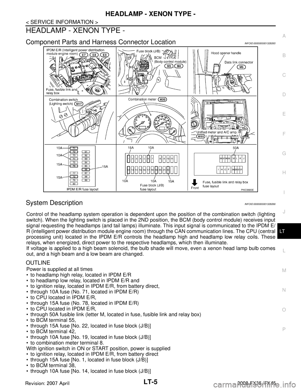
Component Parts and Har ness Connector LocationINFOID:0000000001328265
System DescriptionINFOID:0000000001328266
Control of the headlamp system operation is dependent upon t he position of the combination switch (lighting
switch). When the lighting switch is placed in the 2ND position, the BCM (body control module) receives input
signal requesting the headlamps (and tail lamps) illuminate. This input signal is communicated to the IPDM E/
R (intelligent power distribution module engine room) through the CAN communication lines. The CPU (central
processing unit) located in the IPDM E/R contro ls the headlamp high and headlamp low relay coils. These
relays, when energized, direct power to the respective headlamps, which then illuminate.
If voltage is applied to a high beam solenoid, the bulb shade will move, even a xenon head lamp bulb comes
out, and a high beam and a low beam are changed.
OUTLINE
Power is supplied at all times
to headlamp high relay, located in IPDM E/R
to headlamp low relay, located in IPDM E/R and
to ignition relay, located in IPDM E/R, from battery direct,
through 10A fuse (No. 71, located in IPDM E/R)
to CPU located in IPDM E/R,
through 15A fuse (No. 78, located in IPDM E/R)
to CPU located in IPDM E/R,
through 50A fusible link (letter M, located in fuse, fusible link and relay box)
to BCM terminal 55,
through 15A fuse [No. 22, located in fuse block (J/B)]
to BCM terminal 42,
through 10A fuse [No. 19, located in fuse block (J/B)]
to combination meter terminal 8.
With ignition switch in ON or START position, power is supplied
to ignition relay, located in IPDM E/R, from battery direct
through 15A fuse [No. 1, located in fuse block (J/B)]
to BCM terminal 38,
through 10A fuse [No. 14, located in fuse block (J/B)]
PKIC9683E
3AA93ABC3ACD3AC03ACA3AC03AC63AC53A913A773A893A873A873A8E3A773A983AC73AC93AC03AC3
3A893A873A873A8F3A773A9D3AAF3A8A3A8C3A863A9D3AAF3A8B3A8C
Page 3108 of 3924

LT-6
< SERVICE INFORMATION >
HEADLAMP - XENON TYPE -
to combination meter terminal 7.
With ignition switch in ACC or ON position, power is supplied
through 10A fuse [No. 6, located in fuse block (J/B)]
to BCM terminal 11.
Ground is supplied
to BCM terminals 49 and 52
through grounds M35, M45 and M85,
to IPDM E/R terminals 38 and 60
through grounds E21, E50 and E51,
to combination meter terminals 5, 6 and 15
through grounds M35, M45 and M85.
HEADLAMP OPERATION
Low Beam Operation
With the lighting switch in the 2ND position, the BCM receives input signal requesting the headlamps to illumi-
nate. This input signal is communicated to the IP DM E/R through the CAN communication lines. The CPU
located in the IPDM E/R controls the headlamp lo w relay coil, which when energized, directs power
through 15A fuse (No. 76, located in IPDM E/R)
through IPDM E/R terminal 20
to front combination lamp RH terminal 6,
through 15A fuse (No. 86, located in IPDM E/R)
through IPDM E/R terminal 30
to front combination lamp LH terminal 6.
Ground is supplied
to front combination lamp RH and LH terminals 7
through grounds E21, E50 and E51,
With power and ground supplied, low beam headlamps illuminate.
High Beam Operation/Flash-to-Pass Operation
With the lighting switch in the 2ND position and placed in the HIGH or PASS position, the BCM receives input
signal requesting the headlamp high beams to illuminate. Th is input signal is communicated to the IPDM E/R
through the CAN communication lines. The CPU located in the IPDM E/R controls the headlamp high relay
coil and low relay coil, which when energized, directs power
through 15A fuse (No. 76, located in IPDM E/R)
through IPDM E/R terminal 20
to front combination lamp RH terminal 6,
through 15A fuse (No. 86, located in IPDM E/R)
through IPDM E/R terminal 30
to front combination lamp LH terminal 6,
through 10A fuse (No. 72, located in IPDM E/R)
through IPDM E/R terminal 27
to front combination lamp RH terminal 5,
through 10A fuse (No. 74, located in IPDM E/R)
through IPDM E/R terminal 28
to front combination lamp LH terminal 5.
Ground is supplied
to front combination lamp RH and LH terminals 7
through grounds E21, E50 and E51,
With power and ground supplied, the high beam headlamps illuminate.
If voltage is applied to a high beam solenoid, the bulb shade will move, even a xenon head lamp bulb comes
out, and a high beam and a low beam are changed.
The unified meter and A/C amp. that received the hi gh beam request signal by BCM through the CAN commu-
nication makes a high beam indicator lamp turn on in combination meter.
COMBINATION SWITCH READING FUNCTION
Refer to BCS-4, "System Description".
EXTERIOR LAMP BATTERY SAVER CONTROL
When the combination switch (lighting switch) is in the 2ND position (ON), and the ignition switch is turned
from ON or ACC to OFF, the battery saver control function is activated.
Under this condition, the headlamps remain illumi nated for 5 minutes, then the headlamps are turned OFF.
3AA93ABC3ACD3AC03ACA3AC03AC63AC53A913A773A893A873A873A8E3A773A983AC73AC93AC03AC3
3A893A873A873A8F3A773A9D3AAF3A8A3A8C3A863A9D3AAF3A8B3A8C
Page 3115 of 3924

HEADLAMP - XENON TYPE -LT-13
< SERVICE INFORMATION >
C
DE
F
G H
I
J
L
M A
B
LT
N
O P
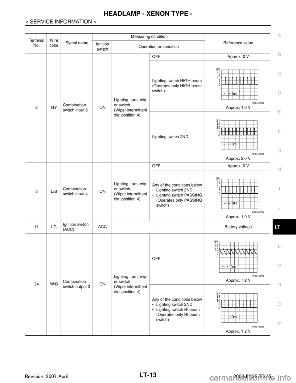
Te r m i n a l No. Wire
color Signal name Measuring condition
Reference value
Ignition
switch Operation or condition
2GY Combination
switch input 5 ONLighting, turn, wip-
er switch
(Wiper intermittent
dial position 4) OFF Approx. 0 V
Lighting switch HIGH beam
(Operates only HIGH beam
switch)
Approx. 1.0 V
Lighting switch 2ND Approx. 2.0 V
3L/B Combination
switch input 4 ONLighting, turn, wip-
er switch
(Wiper intermittent
dial position 4) OFF Approx. 0 V
Any of the conditions below
Lighting switch 2ND
Lighting switch PASSING
(Operates only PASSING
switch)
Approx. 1.0 V
11 L G Ignition switch
(ACC) ACC — Battery voltage
34 W/B Combination
switch output 3 ONLighting, turn, wip-
er switch
(Wiper intermittent
dial position 4) OFF
Approx. 7.2 V
Any of the conditions below
Lighting switch 2ND
Lighting switch HI beam (Operates only HI beam
switch)
Approx. 1.2 V
PKIB4959J
PKIB4953J
PKIB4959J
PKIB4960J
PKIB4958J
3AA93ABC3ACD3AC03ACA3AC03AC63AC53A913A773A893A873A873A8E3A773A983AC73AC93AC03AC3
3A893A873A873A8F3A773A9D3AAF3A8A3A8C3A863A9D3AAF3A8B3A8C
Page 3116 of 3924

LT-14
< SERVICE INFORMATION >
HEADLAMP - XENON TYPE -
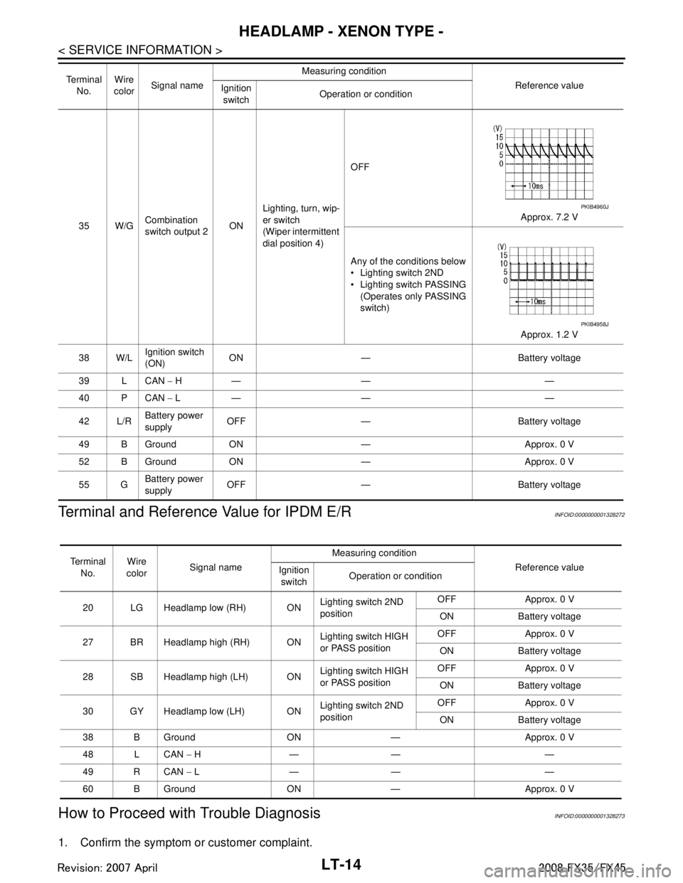
Terminal and Reference Value for IPDM E/R
INFOID:0000000001328272
How to Proceed with Trouble DiagnosisINFOID:0000000001328273
1. Confirm the symptom or customer complaint.
35 W/G Combination
switch output 2 ONLighting, turn, wip-
er switch
(Wiper intermittent
dial position 4) OFF
Approx. 7.2 V
Any of the conditions below
Lighting switch 2ND
Lighting switch PASSING (Operates only PASSING
switch)
Approx. 1.2 V
38 W/L Ignition switch
(ON)
ON — Battery voltage
39 L CAN − H— — —
40 P CAN − L— — —
42 L/R Battery power
supply
OFF — Battery voltage
49 B Ground ON — Approx. 0 V
52 B Ground ON — Approx. 0 V
55 G Battery power
supply OFF — Battery voltage
Te r m i n a l
No. Wire
color Signal name Measuring condition
Reference value
Ignition
switch Operation or condition
PKIB4960J
PKIB4958J
Te r m i n a l
No. Wire
color Signal name Measuring condition
Reference value
Ignition
switch Operation or condition
20 LG Headlamp low (RH) ON Lighting switch 2ND
positionOFF Approx. 0 V
ON Battery voltage
27 BR Headlamp high (RH) ON Lighting switch HIGH
or PASS positionOFF Approx. 0 V
ON Battery voltage
28 SB Headlamp high (LH) ON Lighting switch HIGH
or PASS positionOFF Approx. 0 V
ON Battery voltage
30 GY Headlamp low (LH) ON Lighting switch 2ND
positionOFF Approx. 0 V
ON Battery voltage
38 B Ground ON — Approx. 0 V
48 L CAN − H— — —
49 R CAN − L— — —
60 B Ground ON — Approx. 0 V
3AA93ABC3ACD3AC03ACA3AC03AC63AC53A913A773A893A873A873A8E3A773A983AC73AC93AC03AC3
3A893A873A873A8F3A773A9D3AAF3A8A3A8C3A863A9D3AAF3A8B3A8C
Page 3117 of 3924

HEADLAMP - XENON TYPE -LT-15
< SERVICE INFORMATION >
C
DE
F
G H
I
J
L
M A
B
LT
N
O P
2. Understand operation description and function description. Refer to LT- 5 , "System Description".
3. Perform Preliminary Check. Refer to LT-15, "
Preliminary Check".
4. Check symptom and repair or replace the cause of malfunction.
5. Does headlamp operate normally? If YES, GO TO 6. If NO, GO TO 4.
6. INSPECTION END
Preliminary CheckINFOID:0000000001328274
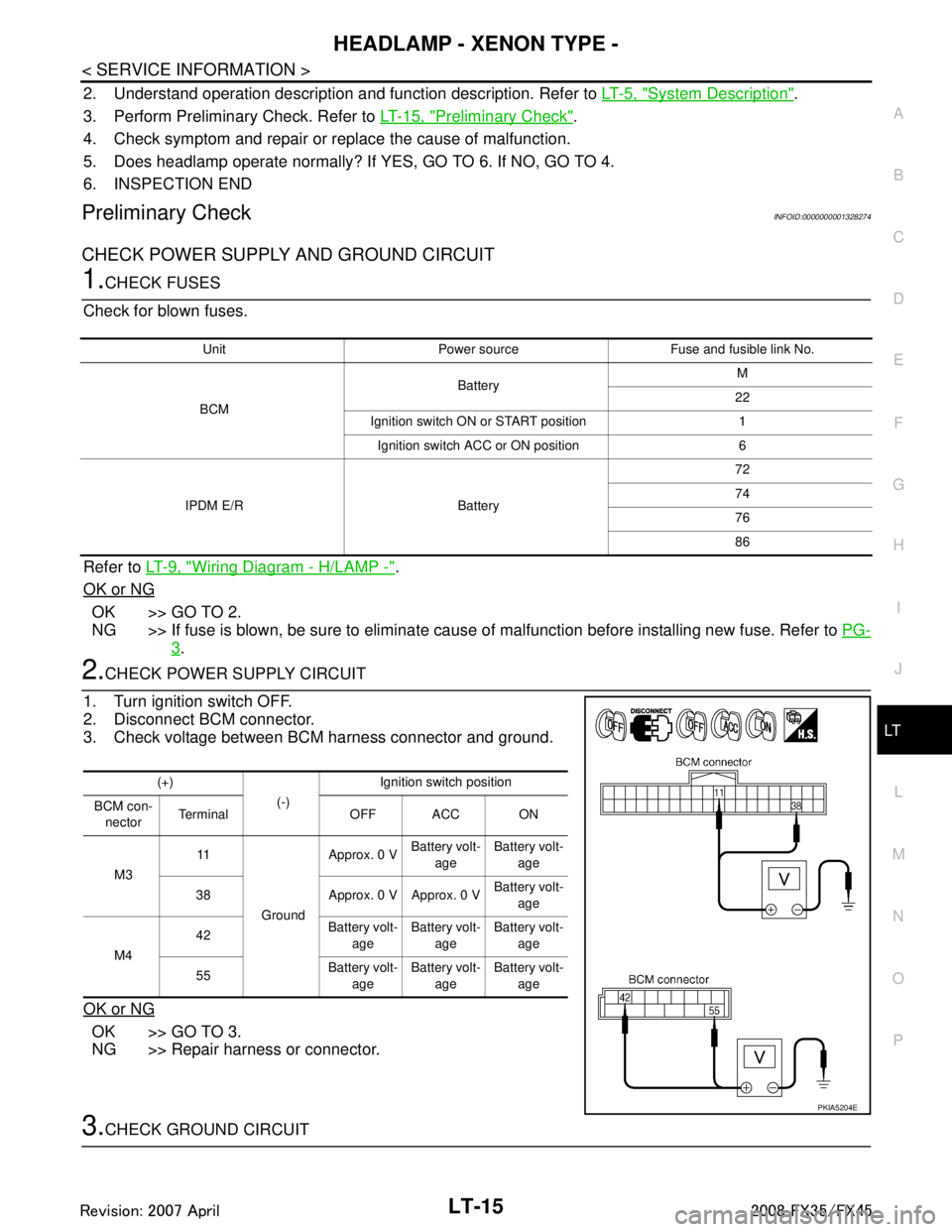
CHECK POWER SUPPLY AND GROUND CIRCUIT
1.CHECK FUSES
Check for blown fuses.
Refer to LT- 9 , "
Wiring Diagram - H/LAMP -".
OK or NG
OK >> GO TO 2.
NG >> If fuse is blown, be sure to eliminate caus e of malfunction before installing new fuse. Refer to PG-
3.
2.CHECK POWER SUPPLY CIRCUIT
1. Turn ignition switch OFF.
2. Disconnect BCM connector.
3. Check voltage between BCM harness connector and ground.
OK or NG
OK >> GO TO 3.
NG >> Repair harness or connector.
3.CHECK GROUND CIRCUIT
Unit Power source Fuse and fusible link No.
BCM Battery
M
22
Ignition switch ON or START position 1 Ignition switch ACC or ON position 6
IPDM E/R Battery 72
74
76
86
(+)
(-)Ignition switch position
BCM con- nector Terminal OFF ACC ON
M3 11
Ground Approx. 0 V
Battery volt-
age Battery volt-
age
38 Approx. 0 V Approx. 0 V Battery volt-
age
M4 42
Battery volt-
age Battery volt-
age Battery volt-
age
55 Battery volt-
age Battery volt-
age Battery volt-
age
PKIA5204E
3AA93ABC3ACD3AC03ACA3AC03AC63AC53A913A773A893A873A873A8E3A773A983AC73AC93AC03AC3
3A893A873A873A8F3A773A9D3AAF3A8A3A8C3A863A9D3AAF3A8B3A8C