2008 INFINITI FX35 engine
[x] Cancel search: enginePage 3066 of 3924
![INFINITI FX35 2008 Service Manual
LAN-46
< SERVICE INFORMATION >[CAN]
TROUBLE DIAGNOSIS
NOTE:
CAN data of the air bag diagnosis sensor unit is not
used by usual service work, thus it is omitted.
TYPE 3
NOTE:
Refer to LAN-37, "
Abbre INFINITI FX35 2008 Service Manual
LAN-46
< SERVICE INFORMATION >[CAN]
TROUBLE DIAGNOSIS
NOTE:
CAN data of the air bag diagnosis sensor unit is not
used by usual service work, thus it is omitted.
TYPE 3
NOTE:
Refer to LAN-37, "
Abbre](/manual-img/42/57017/w960_57017-3065.png)
LAN-46
< SERVICE INFORMATION >[CAN]
TROUBLE DIAGNOSIS
NOTE:
CAN data of the air bag diagnosis sensor unit is not
used by usual service work, thus it is omitted.
TYPE 3
NOTE:
Refer to LAN-37, "
Abbreviation List" for the abbreviations of the connecting units.
T: Transmit R: Receive
Manual mode shift up signal R T
Manual mode signal R T
Not manual mode signal R T
Snow mode switch signal R T
Stop lamp switch signal R T
Turn LED burnout status signal R T
Vehicle speed signal RT
RRRRR T R
A/T shift schedule change demand signal R T
ABS operation signal T
ABS warning lamp signal RT
Brake warning lamp signal RT
SLIP indicator lamp signal RT
TCS operation signal T
VDC OFF indicator lamp signal R T
VDC OFF switch signal T
VDC operation signal T
Front wiper stop position signal R T
High beam status signal R T
Hood switch signal R T
Low beam status signal R T
Rear window defogger control signal R R T Signal name/Connecting unit
ECM
DISP TCM
BCM
I-KEY
STRG M&AABS
ADP
IPDM-E
Signal name/Connecting unitECM
DISP ICC
TCM
BCM
I-KEY
LANE
STRG M&AABS
LASER ADP
IPDM-E
A/C compressor feedback signal T R
A/C compressor request signal T R
Accelerator pedal position signal T R R R
ASCD OD cancel request signal T R
ASCD operation signal T R
Battery voltage signal T R
Closed throttle position signal T R R
Cooling fan speed request signal T R
Engine coolant temperature signal T R
Engine speed signal T R R R R R
Engine status signal T R
Fuel consumption monitor signal TR
RT
3AA93ABC3ACD3AC03ACA3AC03AC63AC53A913A773A893A873A873A8E3A773A983AC73AC93AC03AC3
3A893A873A873A8F3A773A9D3AAF3A8A3A8C3A863A9D3AAF3A8B3A8C
Page 3069 of 3924
![INFINITI FX35 2008 Service Manual
TROUBLE DIAGNOSISLAN-49
< SERVICE INFORMATION > [CAN]
C
D
E
F
G H
I
J
L
M A
B
LAN
N
O P
CAN data of the air bag diagnosis sensor unit is not used by usual service work, thus it is omitted.
TYPE 4/TY INFINITI FX35 2008 Service Manual
TROUBLE DIAGNOSISLAN-49
< SERVICE INFORMATION > [CAN]
C
D
E
F
G H
I
J
L
M A
B
LAN
N
O P
CAN data of the air bag diagnosis sensor unit is not used by usual service work, thus it is omitted.
TYPE 4/TY](/manual-img/42/57017/w960_57017-3068.png)
TROUBLE DIAGNOSISLAN-49
< SERVICE INFORMATION > [CAN]
C
D
E
F
G H
I
J
L
M A
B
LAN
N
O P
CAN data of the air bag diagnosis sensor unit is not used by usual service work, thus it is omitted.
TYPE 4/TYPE 5/TYPE 7
NOTE:
Refer to LAN-37, "
Abbreviation List" for the abbreviations of the connecting units.
T: Transmit R: Receive
Signal name/Connecting unitECM
4WD
DISP TCM
BCM
I-KEY
STRG M&AABS
ADP
IPDM-E
A/C compressor feedback signal T R
A/C compressor request signal T R
Accelerator pedal position signal T R R R
ASCD CRUISE lamp signal T R
ASCD OD cancel request signal T R
ASCD operation signal T R
ASCD SET lamp signal T R
Battery voltage signal T R
Closed throttle position signal T R
Cooling fan speed request signal T R
Engine coolant temperature signal T R
Engine speed signal T R R R R R
Engine status signal T R
Fuel consumption monitor signal TR
RT
Malfunction indicator lamp signal T R
Wide open throttle position signal T R
AWD warning lamp signal T R
A/C switch/indicator signal TR
RT
System setting signal TR R
RT T
A/T CHECK indicato r lamp signal T R
A/T self-diagnosis signal R T
Current gear position signal T R
Manual mode indicator signal T R
Output shaft revolution signal R T
P range signal T R R
Shift position indicator signal T R
Turbine revolution signal R T
A/C switch signal R T
Buzzer output signal TR
TR
Blower fan motor switch signal R T
Day time running light request signal T R
Door lock/unlock status signal T R
Door switch signal R T R R R R
Front fog light request signal T R
Front wiper request signal T R
3AA93ABC3ACD3AC03ACA3AC03AC63AC53A913A773A893A873A873A8E3A773A983AC73AC93AC03AC3
3A893A873A873A8F3A773A9D3AAF3A8A3A8C3A863A9D3AAF3A8B3A8C
Page 3071 of 3924
![INFINITI FX35 2008 Service Manual
TROUBLE DIAGNOSISLAN-51
< SERVICE INFORMATION > [CAN]
C
D
E
F
G H
I
J
L
M A
B
LAN
N
O P
NOTE:
CAN data of the air bag diagnosis sensor unit is not used by usual service work, thus it is omitted.
TYP INFINITI FX35 2008 Service Manual
TROUBLE DIAGNOSISLAN-51
< SERVICE INFORMATION > [CAN]
C
D
E
F
G H
I
J
L
M A
B
LAN
N
O P
NOTE:
CAN data of the air bag diagnosis sensor unit is not used by usual service work, thus it is omitted.
TYP](/manual-img/42/57017/w960_57017-3070.png)
TROUBLE DIAGNOSISLAN-51
< SERVICE INFORMATION > [CAN]
C
D
E
F
G H
I
J
L
M A
B
LAN
N
O P
NOTE:
CAN data of the air bag diagnosis sensor unit is not used by usual service work, thus it is omitted.
TYPE 6/TYPE 8
NOTE:
Refer to LAN-37, "
Abbreviation List" for the abbreviations of the connecting units.
T: Transmit R: Receive
VDC OFF indicator lamp signal RT
VDC OFF switch signal T
VDC operation signal T
Front wiper stop position signal R T
High beam status signal R T
Hood switch signal R T
Low beam status signal R T
Rear window defogger control signal R R T Signal name/Connecting unit
ECM
4WD
DISP TCM
BCM
I-KEY
STRG M&AABS
ADP
IPDM-E
Signal name/Connecting unitECM
4WD
DISP ICC
TCM
BCM
I-KEY
LANE
STRG M&AABS
LASER
ADP
IPDM-E
A/C compressor feedback signal T R
A/C compressor request signal T R
Accelerator pedal position signal T R R R R
ASCD OD cancel request signal T R
ASCD operation signal T R
Battery voltage signal T R
Closed throttle position signal T R R
Cooling fan speed request signal T R
Engine coolant temperature signal T R
Engine speed signal T RRRR RR
Engine status signal T R
Fuel consumption monitor signal TR
RT
ICC steering switch signal T R
Malfunction indicator lamp signal T R
Snow mode switch signal RT
TR
Wide open throttle position signal T R
AWD warning lamp signal T R
A/C switch/indicator signal TR
RT
System setting signal TR R
RT T
Buzzer output signal TR
TR
TR
ICC OD cancel request signal T R
3AA93ABC3ACD3AC03ACA3AC03AC63AC53A913A773A893A873A873A8E3A773A983AC73AC93AC03AC3
3A893A873A873A8F3A773A9D3AAF3A8A3A8C3A863A9D3AAF3A8B3A8C
Page 3092 of 3924
![INFINITI FX35 2008 Service Manual
LAN-72
< SERVICE INFORMATION >[CAN]
TROUBLE DIAGNOSIS
OK or NG
OK >> Present error: Check the following items again.
- Decision of CAN system type.
- Not received CONSULT-III data [SELF-DIAG RESUL INFINITI FX35 2008 Service Manual
LAN-72
< SERVICE INFORMATION >[CAN]
TROUBLE DIAGNOSIS
OK or NG
OK >> Present error: Check the following items again.
- Decision of CAN system type.
- Not received CONSULT-III data [SELF-DIAG RESUL](/manual-img/42/57017/w960_57017-3091.png)
LAN-72
< SERVICE INFORMATION >[CAN]
TROUBLE DIAGNOSIS
OK or NG
OK >> Present error: Check the following items again.
- Decision of CAN system type.
- Not received CONSULT-III data [SELF-DIAG RESULTS, CAN DIAG SUPPORT MNTR (“ECU
list” included)].
- Not copied from on-board diagnosis.
- Procedure for detecting root cause.
Past error: Error was detected in the main li ne between the ABS actuator and electric unit (con-
trol unit) and the driver seat control unit.
NG >> Repair the main line between the harness connectors B5 and B8.
ECM Branch Line CircuitINFOID:0000000001328654
INSPECTION PROCEDURE
1.CHECK CONNECTOR
1. Turn the ignition switch OFF.
2. Disconnect the battery cable from the negative terminal.
3. Check the terminals and connectors of the ECM for damage, bend and loose connection (unit side and connector side).
OK or NG
OK >> GO TO 2.
NG >> Repair the terminal and connector.
2.CHECK HARNESS FOR OPEN CIRCUIT
1. Disconnect the connector of ECM.
2. Check the resistance between the ECM harness connector terminals.
OK or NG
OK >> GO TO 3.
NG >> Repair the ECM branch line.
3.CHECK POWER SUPPLY AND GROUND CIRCUIT
Check the power supply and the ground circuit of the ECM. Refer to EC-141, "
Diagnosis Procedure"
(VQ35DE), EC-719, "Diagnosis Procedure" (VK45DE).
OK or NG
OK >> Present error: Replace the ECM. Refer to EC-100, "Engine Control Component Parts Loca-
tion"(VQ35DE), EC-677, "Engine Control Component Parts Location" (VK45DE).
Past error: Error was detected in the ECM branch line.
NG >> Repair the power supply and the ground circuit.
AWD Control Unit Branch Line CircuitINFOID:0000000001328655
INSPECTION PROCEDURE
1.CHECK CONNECTOR
1. Turn the ignition switch OFF.
2. Disconnect the battery cable from the negative terminal.
Harness connector Harness connector Continuity
Connector No. Terminal No. Connector No. Terminal No.
B5 4
B8 10 Yes
10 9 Yes
ECM harness connector Resistance (Ω)
Connector No. Terminal No.
M90 94 86 Approx. 108 – 132
3AA93ABC3ACD3AC03ACA3AC03AC63AC53A913A773A893A873A873A8E3A773A983AC73AC93AC03AC3
3A893A873A873A8F3A773A9D3AAF3A8A3A8C3A863A9D3AAF3A8B3A8C
Page 3107 of 3924

HEADLAMP - XENON TYPE -LT-5
< SERVICE INFORMATION >
C
DE
F
G H
I
J
L
M A
B
LT
N
O P
HEADLAMP - XENON TYPE -
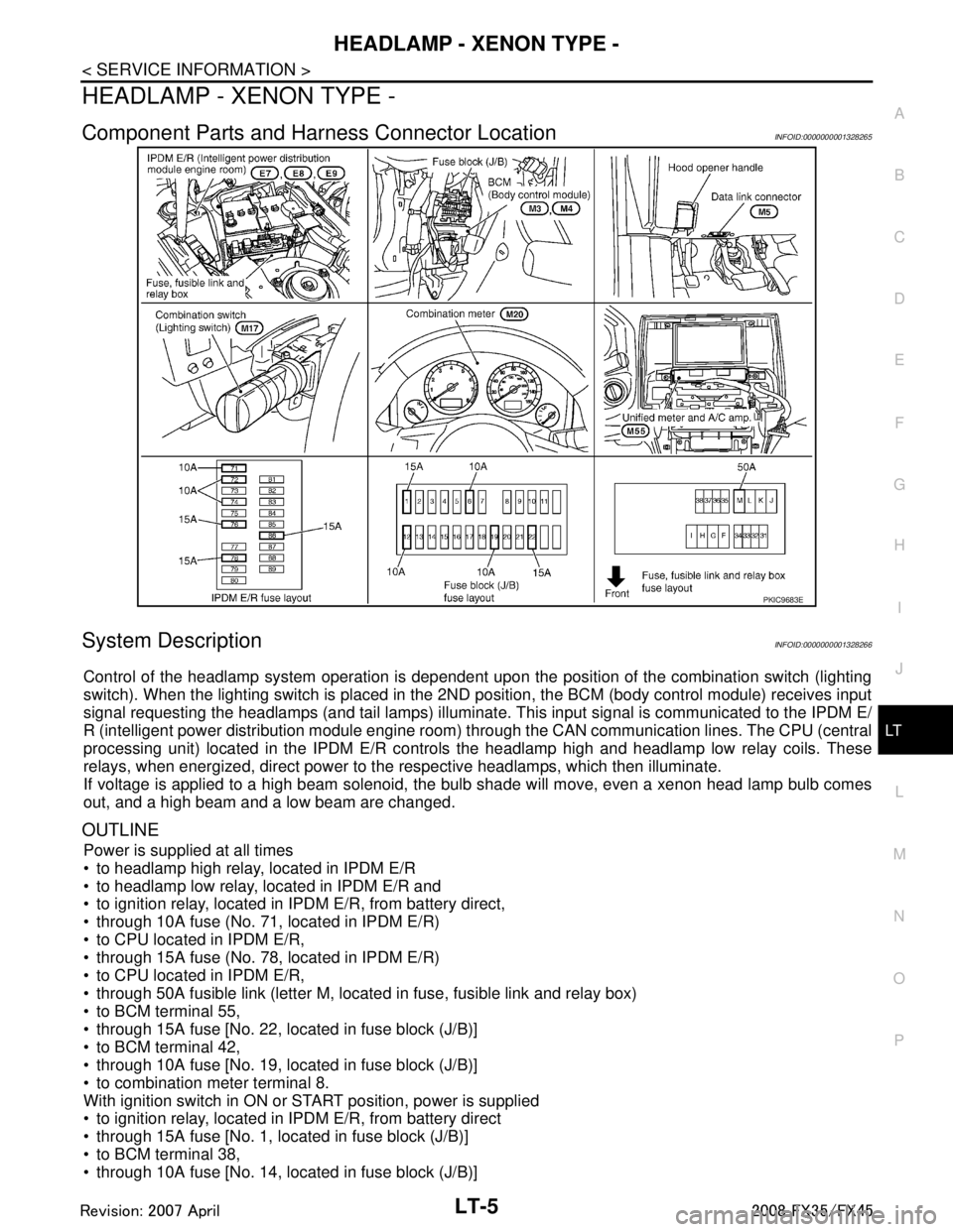
Component Parts and Har ness Connector LocationINFOID:0000000001328265
System DescriptionINFOID:0000000001328266
Control of the headlamp system operation is dependent upon t he position of the combination switch (lighting
switch). When the lighting switch is placed in the 2ND position, the BCM (body control module) receives input
signal requesting the headlamps (and tail lamps) illuminate. This input signal is communicated to the IPDM E/
R (intelligent power distribution module engine room) through the CAN communication lines. The CPU (central
processing unit) located in the IPDM E/R contro ls the headlamp high and headlamp low relay coils. These
relays, when energized, direct power to the respective headlamps, which then illuminate.
If voltage is applied to a high beam solenoid, the bulb shade will move, even a xenon head lamp bulb comes
out, and a high beam and a low beam are changed.
OUTLINE
Power is supplied at all times
to headlamp high relay, located in IPDM E/R
to headlamp low relay, located in IPDM E/R and
to ignition relay, located in IPDM E/R, from battery direct,
through 10A fuse (No. 71, located in IPDM E/R)
to CPU located in IPDM E/R,
through 15A fuse (No. 78, located in IPDM E/R)
to CPU located in IPDM E/R,
through 50A fusible link (letter M, located in fuse, fusible link and relay box)
to BCM terminal 55,
through 15A fuse [No. 22, located in fuse block (J/B)]
to BCM terminal 42,
through 10A fuse [No. 19, located in fuse block (J/B)]
to combination meter terminal 8.
With ignition switch in ON or START position, power is supplied
to ignition relay, located in IPDM E/R, from battery direct
through 15A fuse [No. 1, located in fuse block (J/B)]
to BCM terminal 38,
through 10A fuse [No. 14, located in fuse block (J/B)]
PKIC9683E
3AA93ABC3ACD3AC03ACA3AC03AC63AC53A913A773A893A873A873A8E3A773A983AC73AC93AC03AC3
3A893A873A873A8F3A773A9D3AAF3A8A3A8C3A863A9D3AAF3A8B3A8C
Page 3119 of 3924

HEADLAMP - XENON TYPE -LT-17
< SERVICE INFORMATION >
C
DE
F
G H
I
J
L
M A
B
LT
N
O P
NOTE:
1. Vehicles without auto light system display this item, but cannot be monitored.
2. Vehicles without daytime light system display this item, but cannot be monitored.
3. This item is displayed, but cannot be monitored.
ACTIVE TEST
Display Item List
NOTE:
1. Vehicles without daytime light lamp system display this item, but cannot be tested.
2. This item is displayed, but cannot be tested.
CONSULT-III Functions (IPDM E/R)INFOID:0000000001328276
CONSULT-III can display each diagnostic item us ing the diagnostic test modes shown following.
CONSULT-III BASIC OPERATION
Refer to GI-34, "Description".
DATA MONITOR
All Signals, Main Signals, Selection From Menu
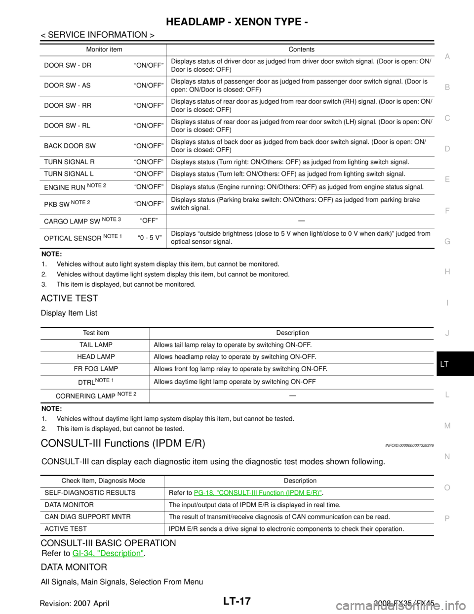
DOOR SW - DR “ON/OFF” Displays status of driver door as judged from driver door switch signal. (Door is open: ON/
Door is closed: OFF)
DOOR SW - AS “ON/OFF” Displays status of passenger door as judged from passenger door switch signal. (Door is
open: ON/Door is closed: OFF)
DOOR SW - RR “ON/OFF” Displays status of rear door as judged from rear door switch (RH) signal. (Door is open: ON/
Door is closed: OFF)
DOOR SW - RL “ON/OFF” Displays status of rear door as judged from rear door switch (LH) signal. (Door is open: ON/
Door is closed: OFF)
BACK DOOR SW “ON/OFF” Displays status of back door as judged from back door switch signal. (Door is open: ON/
Door is closed: OFF)
TURN SIGNAL R “ON/OFF” Display s status (Turn right: ON/Others: OFF) as judged from lighting switch signal.
TURN SIGNAL L “ON/OFF” Display s status (Turn left: ON/Others: OFF) as judged from lighting switch signal.
ENGINE RUN
NOTE 2“ON/OFF” Displays status (Engine running: ON/Others: OFF) as judged from engine status signal.
PKB SW
NOTE 2“ON/OFF” Displays status (Parking brake switch: ON/Others: OFF) as judged from parking brake
switch signal.
CARGO LAMP SW
NOTE 3 “OFF” —
OPTICAL SENSOR
NOTE 1 “0 - 5 V” Displays “outside brightness (close to 5 V when light/close to 0 V when dark)” judged from
optical sensor signal.
Monitor item Contents
Te s t i t e m D e s c r i p t i o n
TAIL LAMP Allows tail lamp relay to operate by switching ON-OFF.
HEAD LAMP Allows headlamp relay to operate by switching ON-OFF.
FR FOG LAMP Allows front fog lamp relay to operate by switching ON-OFF.
DTRL
NOTE 1Allows daytime light lamp operate by switching ON-OFF
CORNERING LAMP
NOTE 2—
Check Item, Diagnosis Mode Description
SELF-DIAGNOSTIC RESULTS Refer to PG-18, "
CONSULT-III Function (IPDM E/R)".
DATA MONITOR The input/output data of IPDM E/R is displayed in real time.
CAN DIAG SUPPORT MNTR The result of transmit/receive diagnosis of CAN communication can be read.
ACTIVE TEST IPDM E/R sends a drive signal to electronic components to check their operation.
3AA93ABC3ACD3AC03ACA3AC03AC63AC53A913A773A893A873A873A8E3A773A983AC73AC93AC03AC3
3A893A873A873A8F3A773A9D3AAF3A8A3A8C3A863A9D3AAF3A8B3A8C
Page 3129 of 3924

HEADLAMP - XENON TYPE -LT-27
< SERVICE INFORMATION >
C
DE
F
G H
I
J
L
M A
B
LT
N
O P
Xenon Headlamp Trouble DiagnosisINFOID:0000000001328286
1.CHECK 1: XENON HEADLAMP LIGHTING
Install normal xenon bulb to corresponding xenon bulb headlamp, and check if lamp lights up.
OK or NG
OK >> Replace xenon bulb.
NG >> GO TO 2.
2.CHECK 2: XENON HEADLAMP LIGHTING
Install normal HID control unit to corresponding xenon headlamp, and check if lamp lights up.
OK or NG
OK >> Replace HID control unit.
NG >> GO TO 3.
3.CHECK 3: XENON HEADLAMP LIGHTING
Install normal xenon lamp housing assembly to corresponding xenon headlamp, and check if lamp lights up.
OK or NG
OK >> Replace xenon headlamp housing assembly. [Malfunction in starter (boosting circuit) in xenon headlamp housing]
NG >> INSPECTION END
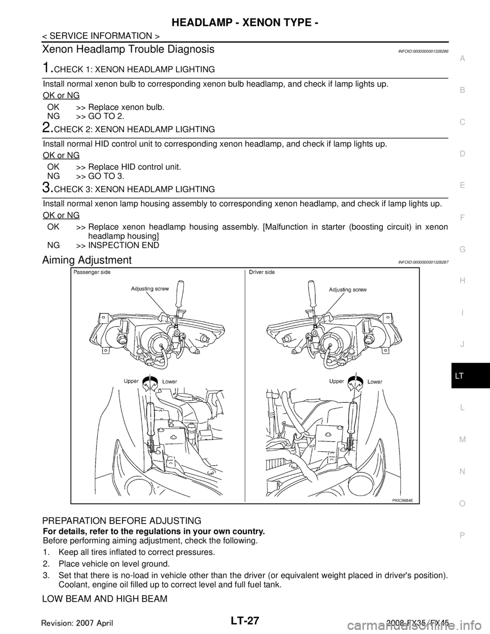
Aiming AdjustmentINFOID:0000000001328287
PREPARATION BEFORE ADJUSTING
For details, refer to the regulations in your own country.
Before performing aiming adjustment, check the following.
1. Keep all tires inflated to correct pressures.
2. Place vehicle on level ground.
3. Set that there is no-load in vehicle other than the driv er (or equivalent weight placed in driver's position).
Coolant, engine oil filled up to correct level and full fuel tank.
LOW BEAM AND HIGH BEAM
PKIC9684E
3AA93ABC3ACD3AC03ACA3AC03AC63AC53A913A773A893A873A873A8E3A773A983AC73AC93AC03AC3
3A893A873A873A8F3A773A9D3AAF3A8A3A8C3A863A9D3AAF3A8B3A8C
Page 3134 of 3924

LT-32
< SERVICE INFORMATION >
DAYTIME LIGHT SYSTEM
DAYTIME LIGHT SYSTEM
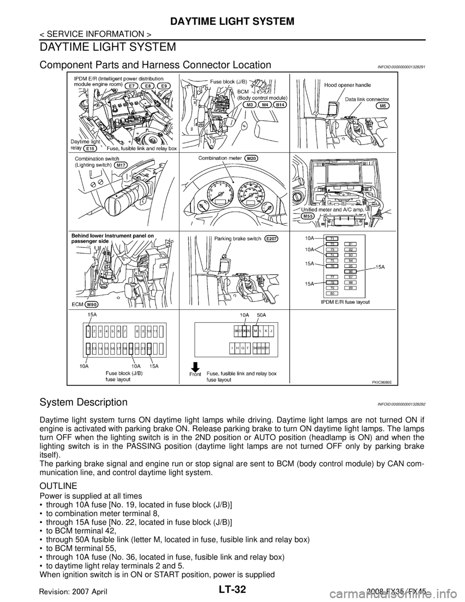
Component Parts and Harness Connector LocationINFOID:0000000001328291
System DescriptionINFOID:0000000001328292
Daytime light system turns ON daytime light lamps while driving. Daytime light lamps are not turned ON if
engine is activated with parking brake ON. Release parki ng brake to turn ON daytime light lamps. The lamps
turn OFF when the lighting switch is in the 2ND pos ition or AUTO position (headlamp is ON) and when the
lighting switch is in the PASSING position (daytime light lamps are not turned OFF only by parking brake
itself).
The parking brake signal and engine run or stop signal ar e sent to BCM (body control module) by CAN com-
munication line, and control daytime light system.
OUTLINE
Power is supplied at all times
through 10A fuse [No. 19, located in fuse block (J/B)]
to combination meter terminal 8,
through 15A fuse [No. 22, located in fuse block (J/B)]
to BCM terminal 42,
through 50A fusible link (letter M, located in fuse, fusible link and relay box)
to BCM terminal 55,
through 10A fuse (No. 36, located in fuse, fusible link and relay box)
to daytime light relay terminals 2 and 5.
When ignition switch is in ON or START position, power is supplied
PKIC9686E
3AA93ABC3ACD3AC03ACA3AC03AC63AC53A913A773A893A873A873A8E3A773A983AC73AC93AC03AC3
3A893A873A873A8F3A773A9D3AAF3A8A3A8C3A863A9D3AAF3A8B3A8C