2008 INFINITI FX35 ECO mode
[x] Cancel search: ECO modePage 1053 of 3924
![INFINITI FX35 2008 Service Manual
BRC-38
< SERVICE INFORMATION >[VDC/TCS/ABS]
TROUBLE DIAGNOSIS FOR SYSTEM
1. Disconnect ABS actuator and electric unit (contro
l unit) connector. Then reconnect it securely.
2. Perform self-diagnosis INFINITI FX35 2008 Service Manual
BRC-38
< SERVICE INFORMATION >[VDC/TCS/ABS]
TROUBLE DIAGNOSIS FOR SYSTEM
1. Disconnect ABS actuator and electric unit (contro
l unit) connector. Then reconnect it securely.
2. Perform self-diagnosis](/manual-img/42/57017/w960_57017-1052.png)
BRC-38
< SERVICE INFORMATION >[VDC/TCS/ABS]
TROUBLE DIAGNOSIS FOR SYSTEM
1. Disconnect ABS actuator and electric unit (contro
l unit) connector. Then reconnect it securely.
2. Perform self-diagnosis again.
Do any self-diagnosis item appear?
YES >> GO TO 3.
NO >> Poor connection. Repair or replace the applicable connector.
3.CHECK ABS MOTOR AND MOTOR RELAY POWER SUPPLY CIRCUIT
1. Turn ignition switch OFF and disconnect ABS actuat or and electric unit (control unit) connector E56.
2. Check voltage between ABS actuator and electric unit (control unit) harness connector and ground.
3. Check continuity between ABS ac tuator and electric unit (control
unit) harness connector and ground.
OK or NG
OK >> Perform self-diagnosis again. If the same result appears, replace ABS actuator and electric unit (control
unit). Refer to BRC-54
.
NG >> Repair harness or connectors.
DTC C1113 G-SENSORINFOID:0000000001327682
CAUTION:
Sudden turns (such as spin turns, acceleration turns), drifting, etc. may cause the G sensor circuit
indicate a malfunction. However, this is not a malf unction, if normal operation can be resumed after
restarting engine.
INSPECTION PROCEDURE
1.CHECK SELF-DIAGNOSTIC RESULTS
Check the self-diagnostic results.
CAUTION:
When on a turntable, such as at a parking structure entrance, or wh en on a moving object with engine
running, VDC OFF indicator lamp might turn on and self-diagnosis using CONSULT-III the yaw rate
sensor system might be displayed, but in this case ther e is no malfunction in yaw rate sensor circuit.
As soon as vehicle leaves turntable or moving object , restart engine to return the system to normal.
Is the above displayed in the self-diagnosis display items?
YES >> GO TO 2.
NO >> INSPECTION END
2.CHECK CONNECTOR
ABS actuator and electric unit (control unit) Ground Voltage
1, 32 — Battery voltage
(Approx. 12 V)
SFIA1198E
ABS actuator and electric unit (control unit) Ground Continuity
16, 47 — Yes
SFIA1197E
Self-diagnostic resultsYAW RATE SENSOR
SIDE G-SEN CIRCUIT
G-SENSOR (AWD models)
3AA93ABC3ACD3AC03ACA3AC03AC63AC53A913A773A893A873A873A8E3A773A983AC73AC93AC03AC3
3A893A873A873A8F3A773A9D3AAF3A8A3A8C3A863A9D3AAF3A8B3A8C
Page 1054 of 3924
![INFINITI FX35 2008 Service Manual
TROUBLE DIAGNOSIS FOR SYSTEMBRC-39
< SERVICE INFORMATION > [VDC/TCS/ABS]
C
D
E
G H
I
J
K L
M A
B
BRC
N
O P
1. Disconnect G sensor connector and ABS actuator and el ectric unit (control unit) connecto INFINITI FX35 2008 Service Manual
TROUBLE DIAGNOSIS FOR SYSTEMBRC-39
< SERVICE INFORMATION > [VDC/TCS/ABS]
C
D
E
G H
I
J
K L
M A
B
BRC
N
O P
1. Disconnect G sensor connector and ABS actuator and el ectric unit (control unit) connecto](/manual-img/42/57017/w960_57017-1053.png)
TROUBLE DIAGNOSIS FOR SYSTEMBRC-39
< SERVICE INFORMATION > [VDC/TCS/ABS]
C
D
E
G H
I
J
K L
M A
B
BRC
N
O P
1. Disconnect G sensor connector and ABS actuator and el ectric unit (control unit) connector and check ter-
minals for deformation, disconnection, looseness, and so on. If any malfunction is found, repair or replace
terminal.
2. Reconnect connectors and perform a ABS actuator and electric unit (control unit) self-diagnosis again.
OK or NG
OK >> Connector terminal contact is loose, damaged, open or shorted.
NG >> GO TO 3.
3.CHECK G SENSOR HARNESS
1. Turn ignition switch OFF and disconnect G sensor connector M79 (2WD models) or M71 (A WD models) and ABS actuator
and electric unit (control unit) connector E56.
2. Check continuity between ABS ac tuator and electric unit (control
unit) harness connector and G sensor harness connector.
OK or NG
OK >> GO TO 4.
NG >> If the open or short in harness, repair or replace harness.
4.CHECK G SENSOR
1. Connect G sensor connector and ABS actuator and electric unit (control unit) connector.
2. Use CONSULT-III “DATA MONITOR” to check if G sensor are normal.
OK or NG
OK >> Perform ABS actuator and electric unit (control unit) self-diagnosis again.
NG >> Replace malfunctioning G sensor, and then perform self-diagnosis for ABS actuator and electric
unit (control unit) again.
DTC C1115 ABS SENSOR [ABNORMAL SIGNAL]INFOID:0000000001569698
Refer to BRC-34, "DTC C1101 RR RH SENSOR-1".
DTC C1116 STOP LAMP SWINFOID:0000000001327686
INSPECTION PROCEDURE
1.CHECK SELF-DIAGNOSTIC RESULTS
Check the self-diagnostic results.
Is the above displayed in the self-diagnosis display item?
ABS actuator and electric unit (c ontrol unit) G sensor Continuity
63
Ye s
24 5
25 1
29 2
SFIA1192E
Vehicle status
Yaw rate sensor
(Data monitor standard) Side G sensor
(Data monitor standard) Decel G sensor (AWD models)
(Data monitor standard)
When stopped − 4 to + 4 deg/s
− 1.1 to + 1.1 m/s
2− 0 . 11 t o + 0 . 11 G
Right turn Negative value Negative value —
Left turn Positive value Positive value —
Speed up — — Negative value
Speed down — — Positive value
Self-diagnostic results STOP LAMP SW
3AA93ABC3ACD3AC03ACA3AC03AC63AC53A913A773A893A873A873A8E3A773A983AC73AC93AC03AC3
3A893A873A873A8F3A773A9D3AAF3A8A3A8C3A863A9D3AAF3A8B3A8C
Page 1133 of 3924

COMBINATION METERSDI-7
< SERVICE INFORMATION >
C
DE
F
G H
I
J
L
M A
B
DI
N
O P
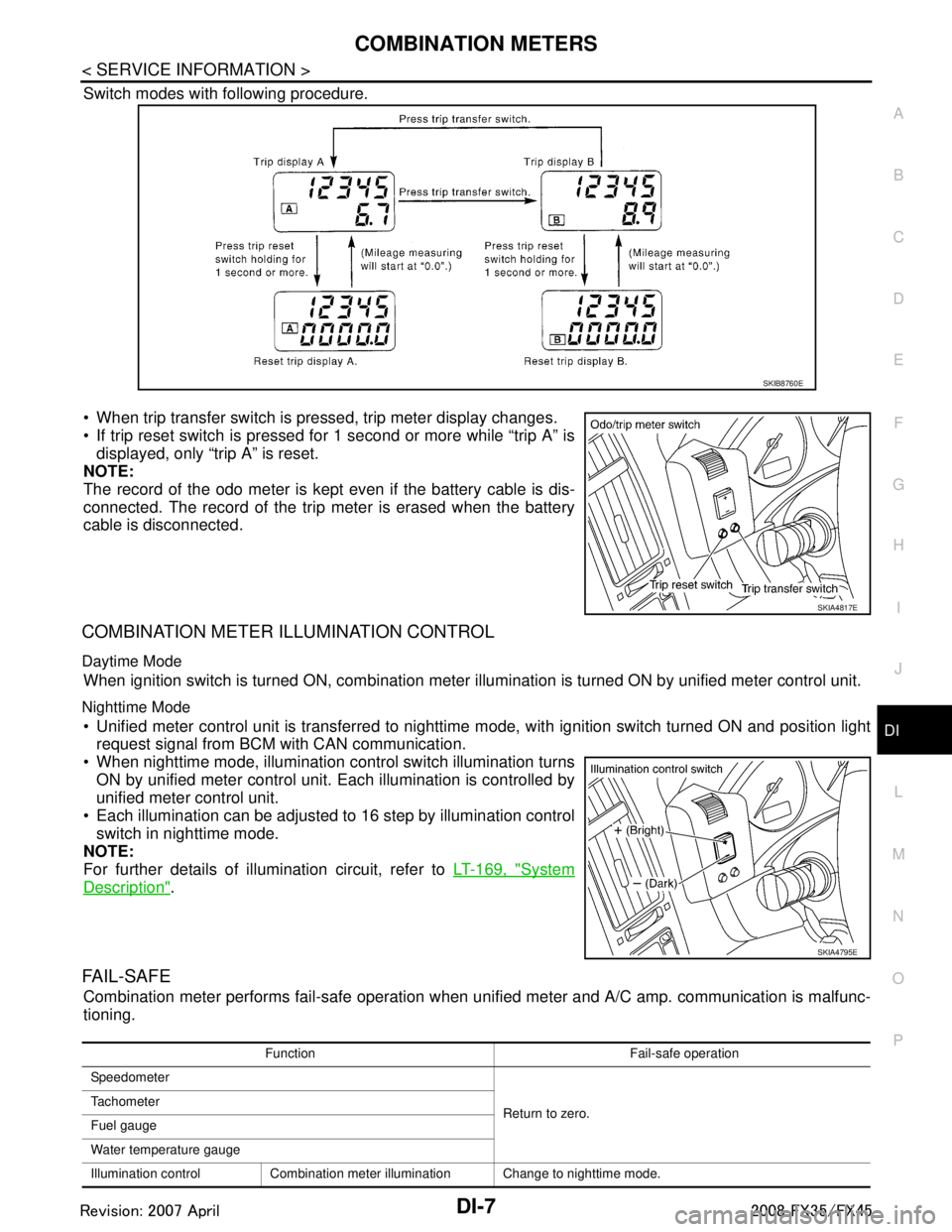
Switch modes with following procedure.
When trip transfer switch is pressed, trip meter display changes.
If trip reset switch is pressed for 1 second or more while “trip A” is displayed, only “trip A” is reset.
NOTE:
The record of the odo meter is kept even if the battery cable is dis-
connected. The record of the trip meter is erased when the battery
cable is disconnected.
COMBINATION METER ILLUMINATION CONTROL
Daytime Mode
When ignition switch is turned ON, combination meter il lumination is turned ON by unified meter control unit.
Nighttime Mode
Unified meter control unit is transferred to nighttime mode, with ignitio\
n switch turned ON and position light
request signal from BCM with CAN communication.
When nighttime mode, illumination c ontrol switch illumination turns
ON by unified meter control unit. Each illumination is controlled by
unified meter control unit.
Each illumination can be adjusted to 16 step by illumination control switch in nighttime mode.
NOTE:
For further details of illumination circuit, refer to LT-169, "
System
Description".
FA I L - S A F E
Combination meter performs fail-safe operation when unified meter and A/C amp. communication is malfunc-
tioning.
SKIB8760E
SKIA4817E
SKIA4795E
Function Fail-safe operation
Speedometer
Return to zero.
Tachometer
Fuel gauge
Water temperature gauge
Illumination control Combination meter illumination Change to nighttime mode.
3AA93ABC3ACD3AC03ACA3AC03AC63AC53A913A773A893A873A873A8E3A773A983AC73AC93AC03AC3
3A893A873A873A8F3A773A9D3AAF3A8A3A8C3A863A9D3AAF3A8B3A8C
Page 1141 of 3924

COMBINATION METERSDI-15
< SERVICE INFORMATION >
C
DE
F
G H
I
J
L
M A
B
DI
N
O P
3. Turn ignition switch ON while pressing trip transfer switch and trip reset switch at the same time.
4. After ignition switch is turned ON, release trip transfer switch and trip reset switch (within 7 seconds after the ignition switch is
turned ON).
5. All the segments on the odo/trip meter, A/T indi cator and ICC system display illuminates, and simulta-
neously the low-fuel warning lamp indicator illuminates. At this time, the unified meter control unit is turned
to self-diagnosis mode.
NOTE:
Check odo/trip meter switch and combination meter power supply and ground circuit when self-diagno-
sis mode of combination meter does not start. Replace combination meter if the results of the check are
normal.
If any of the segments are not disp layed, replace combination meter.
6. Each meter/gauge activates during pressing trip reset switch. (Then low-fuel warning lamp turns OFF.)
NOTE:
If any of the meters/gauges are not activated, replace thecombination meter.
The figure is reference.
CONSULT-III Function (METER/M&A)INFOID:0000000001328441
Refer to DI-27, "CONSULT-III Function (METER/M&A)" in “UNIFIED METER AND A/C AMP”.
Trouble DiagnosisINFOID:0000000001328442
HOW TO PERFORM TROUBLE DIAGNOSIS
1. Confirm the symptom or customer complaint.
2. Perform preliminary check. Refer to "PRELIMINARY CHECK".
3. According to the symptom chart, repair or replace the cause of the symptom. Refer to DI-16, "
Symptom
Chart".
4. Does the meter operate normally? If so, GO TO 5. If not, GO TO 2.
5. INSPECTION END
PRELIMINARY CHECK
1.CHECK OPERATION OF SELF-DIAGNOSIS MODE (COMBINATION METER)
SKIA4817E
SKIA6170E
SKIA4831E
3AA93ABC3ACD3AC03ACA3AC03AC63AC53A913A773A893A873A873A8E3A773A983AC73AC93AC03AC3
3A893A873A873A8F3A773A9D3AAF3A8A3A8C3A863A9D3AAF3A8B3A8C
Page 1154 of 3924

DI-28
< SERVICE INFORMATION >
UNIFIED METER AND A/C AMP
SELF-DIAG RESULTS
Display Item List
NOTE:
“TIME” means the following.
0: Means detected malfunction at present. (From malfunction detection to turning ignition switch OFF)
1 - 63: Means detected malfunction in the past . (Displays the number of ignition switch OFF → ON after
detecting malfunction. “Self Diagnostic Result” is erased when exceeding “63”.)
DATA MONITOR
Display Item List
X: Applicable
System Diagnosis mode Description
METER A/C AMP Self Diagnostic Result
Unified meter and A/C amp. checks the conditions and displays
memorized error.
CAN DIAG SUPPORT MNTR The results of transmit/receive diagnosis of CAN communication
can be read.
Data Monitor Displays unified meter and A/C amp. input data in real time.
Display item [Code] Malfunction is detected when... Reference
page
CAN COMM CIRC [U1000] When unified meter and A/C amp. is not transmitting or receiving CAN communication
signal for 2 seconds or more. DI-30
METER COMM CIRC [B2202]Malfunction is detected in communication of between combination meter and unified
meter and A/C amp.
DI-30
VEHICLE SPEED CIRC [B2205]When an erroneous speed signal is input for 1 second.
NOTE:
Even when there is no malfunction on speed signal system, malfunction may be misin-
terpreted when battery has low voltage (when maintaining 7 - 8 V for about 2 seconds). DI-32
Display item [Unit]
MAIN
SIGNALS SELECTION
FROM MENU Contents
SPEED METER [km/h] or [mph] X X Displays the value of vehicle speed signal, which is input from
ABS actuator and electric unit (control unit).
SPEED OUTPUT [km/h] or [mph] X X Displays the value of vehicle speed signal, which is transmitted
to each unit with CAN communication.
TACHO METER [rpm] X X Displays the value of engine speed signal, which is input from
ECM.
W TEMP METER [ °C] or [ °F] X X Displays the value of engine coolant temperature signal, which is
input from ECM.
FUEL METER [lit.] X X Displays the value, which processes a resistance signal from fuel
gauge.
DISTANCE [km] or [mile] X X Displays the value, which is calculated by vehicle speed signal
from ABS actuator and electric unit
(control unit), fuel gauge and
fuel consumption from ECM.
FUEL W/L [On/Off] X X Indicates [On/Off] condition of low-fuel warning lamp.
MIL [On/Off] X Indicates [On/Off] condition of malfunction indicator lamp.
AIR PRES W/L [On/Off] X Indicates [On/Off] condition of low tire pressure warning lamp.
SEAT BELT W/L [On/Off]
*1X Indicates [On/Off] condition of seat belt warning lamp.
BUZZER [On/Off] X X Indicates [On/Off] condition of buzzer.
DOOR W/L [On/Off] X Indicates [On/Off] condition of door warning lamp.
HI-BEAM IND [On/Off] X Indicates [On/Off] condition of high beam indicator.
TURN IND [On/Off] X Indicates [On/Off] condition of turn indicator.
3AA93ABC3ACD3AC03ACA3AC03AC63AC53A913A773A893A873A873A8E3A773A983AC73AC93AC03AC3
3A893A873A873A8F3A773A9D3AAF3A8A3A8C3A863A9D3AAF3A8B3A8C
Page 1196 of 3924

DI-70
< SERVICE INFORMATION >
LANE DEPARTURE WARNING SYSTEM
- The LDW switch must be pushed to turn on the system.
To the change modes- Push and hold LDW switch for more than 4 seconds, when LDW system ON indicator is off.
- Then LDW chime sounds and blinking of LDW system ON indicator informs that the mode change is com-
pleted.
Temporary disabled status at high temperature
- If the vehicle is parked in direct sunlight under high temperature conditions [approximately over 104 °F
(40 °C)] and then started, the LDW system may sound a ch ime and cancel automatically. Then LDW system
ON indicator will blink.
- When the interior temperature is reduced, the system will resume to operate automatically and the LDW sys-
tem ON indicator illuminates.
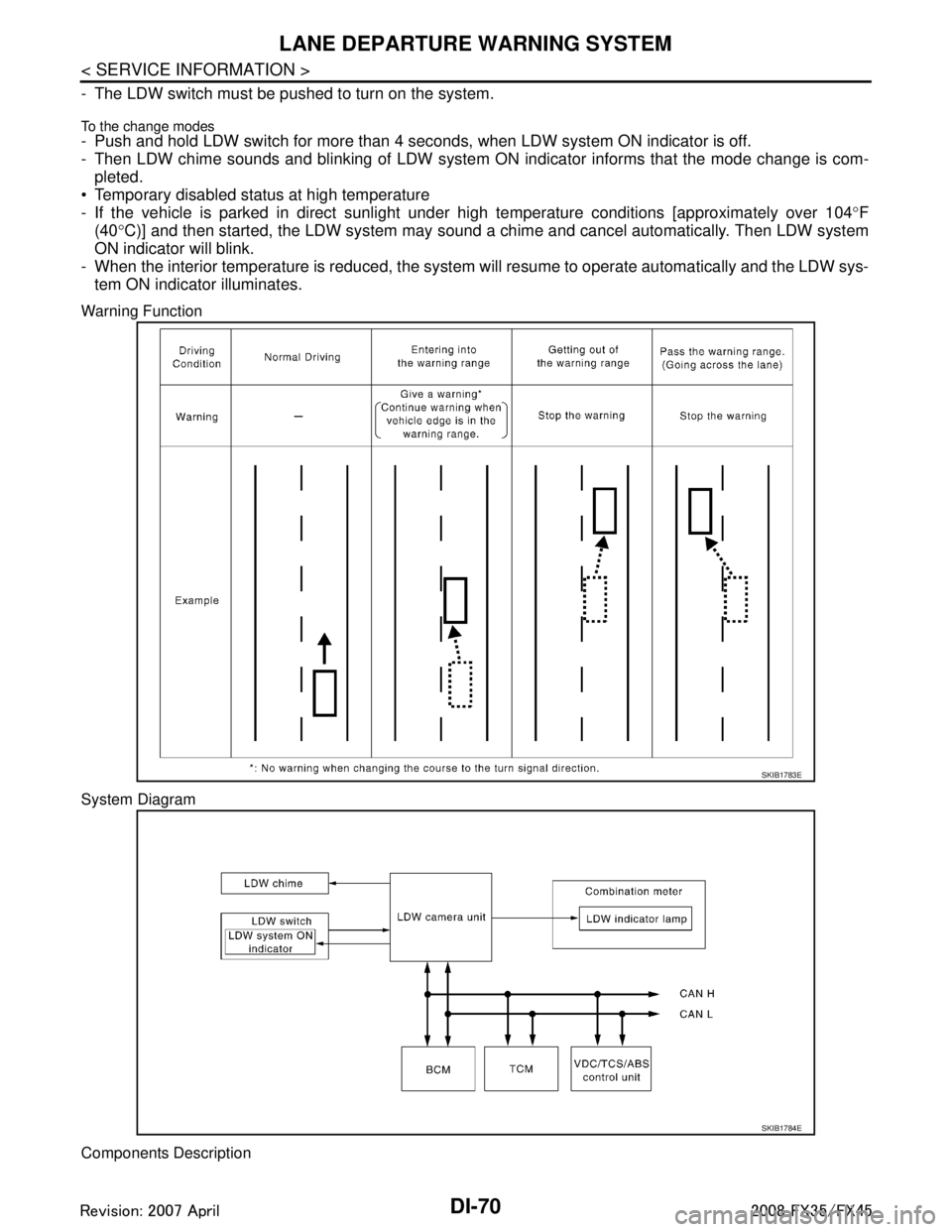
Warning Function
System Diagram
Components Description
SKIB1783E
SKIB1784E
3AA93ABC3ACD3AC03ACA3AC03AC63AC53A913A773A893A873A873A8E3A773A983AC73AC93AC03AC3
3A893A873A873A8F3A773A9D3AAF3A8A3A8C3A863A9D3AAF3A8B3A8C
Page 1212 of 3924

DI-86
< SERVICE INFORMATION >
LANE DEPARTURE WARNING SYSTEM
Perform self-diagnosis of ABS actuator and electric unit (control unit). Refer to \
BRC-26, "CONSULT-III Func-
tions (ABS)".
Self
-diagnosis results
No malfunction detected >> GO TO 2.
Malfunction detected >> Check applicable parts, and repair or replace corresponding parts.
2.CHECK TCM (CONSULT-III)
Perform self-diagnosis of TCM. Refer to AT-84, "
CONSULT-III Function (TRANSMISSION)".
Self
-diagnosis results
No malfunction detected >> Replace LDW camera unit.
Malfunction detected >> Check applicable parts, and repair or replace corresponding parts.
DTC [C1B03] ABNRML TEMP DETECTINFOID:0000000001328507
1.COOLING CAMERA UNIT
1. Cooling camera unit.
2. Erase DTC and perform self-diagnosis the LDW camera unit.
Self
-diagnosis results
No malfunction detected >> INSPECTION END
Malfunction detected >> Replace LDW camera unit.
DTC [U1000] CAN COMM CIRCUITINFOID:0000000001328508
1.CHECK CAN COMMUNICATION
1. Turn ignition switch ON and wait for 2 seconds or more.
2. Check “Self Diagnostic Result” of “LDW”.
>> Go to “LAN SYSTEM”. Refer to LAN-43, "
CAN System Specification Chart".
DTC [U1010] CONTROL UNIT (CAN)INFOID:0000000001328509
Replace LDW camera unit, when “[U1010] CONTROL UNI T (CAN)” is displayed on self-diagnosis display.
LDW Chime Circuit InspectionINFOID:0000000001328510
1.CHECK LDW CHIME OPERATION
Check LDW chime operation “BUZZER DRIVE” in “Active Test” mode with CONSULT-III.
OK or NG
OK >> INSPECTION END
NG >> GO TO 2.
2.CHECK LDW CHIME POWER SUPPLY CIRCUIT
1. Turn ignition switch OFF.
2. Disconnect LDW chime connector.
3. Turn ignition switch ON. “BUZZER DRIVE”
Select “On” : LDW chime is activated.
Select “Off” : LDW chime is not activated.
3AA93ABC3ACD3AC03ACA3AC03AC63AC53A913A773A893A873A873A8E3A773A983AC73AC93AC03AC3
3A893A873A873A8F3A773A9D3AAF3A8A3A8C3A863A9D3AAF3A8B3A8C
Page 1220 of 3924

DI-94
< SERVICE INFORMATION >
COMPASS
COMPASS
Precaution for CompassINFOID:0000000001328520
NOTE:
Do not install the ski rack, antenna, etc. which is attach to the vehicle with a magnet base. It affects the oper-
ation of the compass.
When cleaning the mirror, use a paper towel or similar material dampened with glass cleaner. Do not spray glass cleaner directly on the mirror as it may c ause the liquid cleaner to enter the mirror housing.
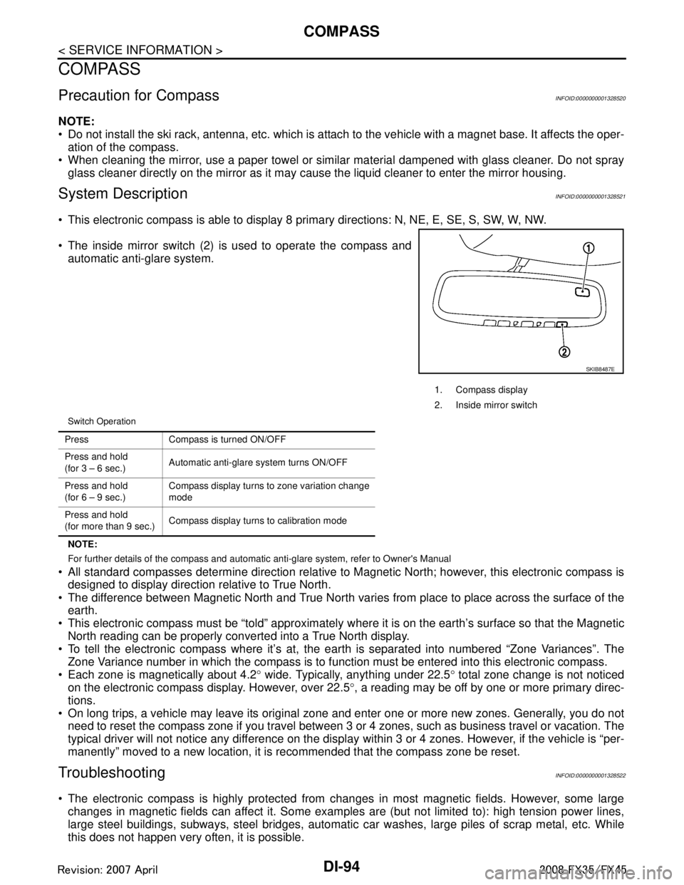
System DescriptionINFOID:0000000001328521
This electronic compass is able to display 8 primary directions: N, NE, E, SE, S, SW, W, NW.
The inside mirror switch (2) is used to operate the compass and
automatic anti-glare system.
Switch Operation
NOTE:
For further details of the compass and automatic anti-glare system, refer to Owner's Manual
All standard compasses determine direction relative to Magnetic North; however, this electronic compass is
designed to display direction relative to True North.
The difference between Magnetic North and True North varies from place to place across the surface of the
earth.
This electronic compass must be “told” approximately w here it is on the earth’s surface so that the Magnetic
North reading can be properly converted into a True North display.
To tell the electronic compass where it’s at, the earth is separated into numbered “Zone Variances”. The
Zone Variance number in which the compass is to function must be entered into this electronic compass.
Each zone is magnetically about 4.2 ° wide. Typically, anything under 22.5 ° total zone change is not noticed
on the electronic compass display. However, over 22.5 °, a reading may be off by one or more primary direc-
tions.
On long trips, a vehicle may leave its original zone and enter one or more new zones. Generally, you do not need to reset the compass zone if you travel between 3 or 4 zones, such as business travel or vacation. The
typical driver will not notice any difference on the display within 3 or 4 zones. However, if the vehicle is “per-
manently” moved to a new location, it is recommended that the compass zone be reset.
TroubleshootingINFOID:0000000001328522
The electronic compass is highly protected from changes in most magnetic fields. However, some large changes in magnetic fields can affect it. Some examples are (but not limited to): high tension power lines,
large steel buildings, subways, steel bridges, automatic car washes, large piles of scrap metal, etc. While
this does not happen very often, it is possible.
1. Compass display
2. Inside mirror switch
SKIB8487E
Press Compass is turned ON/OFF
Press and hold
(for 3 – 6 sec.) Automatic anti-glare system turns ON/OFF
Press and hold
(for 6 – 9 sec.) Compass display turns to zone variation change
mode
Press and hold
(for more than 9 sec.) Compass display turns to calibration mode
3AA93ABC3ACD3AC03ACA3AC03AC63AC53A913A773A893A873A873A8E3A773A983AC73AC93AC03AC3
3A893A873A873A8F3A773A9D3AAF3A8A3A8C3A863A9D3AAF3A8B3A8C