2008 INFINITI FX35 engine
[x] Cancel search: enginePage 2805 of 3924
FFD-14
< SERVICE INFORMATION >
FRONT FINAL DRIVE ASSEMBLY
FRONT FINAL DRIVE ASSEMBLY
Removal and Installation (VQ35DE Models)INFOID:0000000001327485
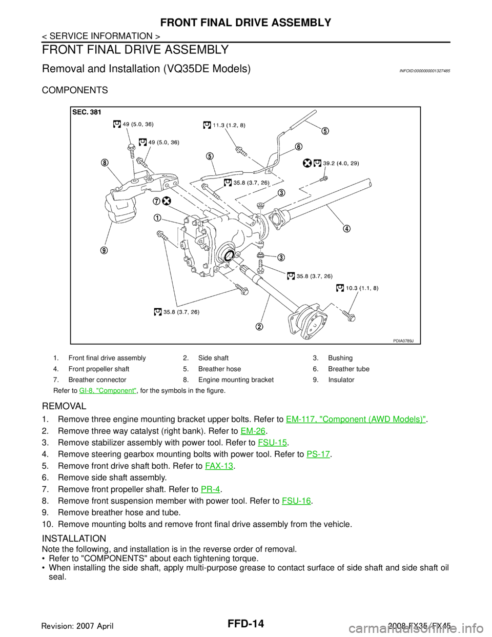
COMPONENTS
REMOVAL
1. Remove three engine mounting bracket upper bolts. Refer to EM-117, "Component (AWD Models)".
2. Remove three way catalyst (right bank). Refer to EM-26
.
3. Remove stabilizer assembly with power tool. Refer to FSU-15
.
4. Remove steering gearbox mounting bolts with power tool. Refer to PS-17
.
5. Remove front drive shaft both. Refer to FA X - 1 3
.
6. Remove side shaft assembly.
7. Remove front propeller shaft. Refer to PR-4
.
8. Remove front suspension member with power tool. Refer to FSU-16
.
9. Remove breather hose and tube.
10. Remove mounting bolts and remove front final drive assembly from the vehicle.
INSTALLATION
Note the following, and installation is in the reverse order of removal.
Refer to "COMPONENTS" about each tightening torque.
When installing the side shaft, apply multi-purpose grease to contact surface of side shaft and side shaft oil
seal.
1. Front final drive assembly 2. Side shaft 3. Bushing
4. Front propeller shaft 5. Breather hose 6. Breather tube
7. Breather connector 8. Engine mounting bracket 9. Insulator
Refer to GI-8, "
Component", for the symbols in the figure.
PDIA0789J
3AA93ABC3ACD3AC03ACA3AC03AC63AC53A913A773A893A873A873A8E3A773A983AC73AC93AC03AC3
3A893A873A873A8F3A773A9D3AAF3A8A3A8C3A863A9D3AAF3A8B3A8C
Page 2807 of 3924
FFD-16
< SERVICE INFORMATION >
FRONT FINAL DRIVE ASSEMBLY
REMOVAL
1. Remove three way catalyst (right bank). Refer to EM-179.
2. Remove stabilizer assembly with power tool. Refer to FSU-15
.
3. Remove steering gearbox mounting bolts with power tool. Refer to PS-17
.
4. Remove front drive shaft both. Refer to FA X - 1 3
.
5. Remove side shaft assembly.
6. Remove front propeller shaft. Refer to PR-4
.
7. Remove front suspension member with power tool. Refer to FSU-16
.
8. Remove engine wire harness clamp bolts from front final drive.
9. Remove breather hose and tube.
10. Remove mounting bolts and remove front final drive assembly from the vehicle.
INSTALLATION
Note the following, and installation is in the reverse order of removal.
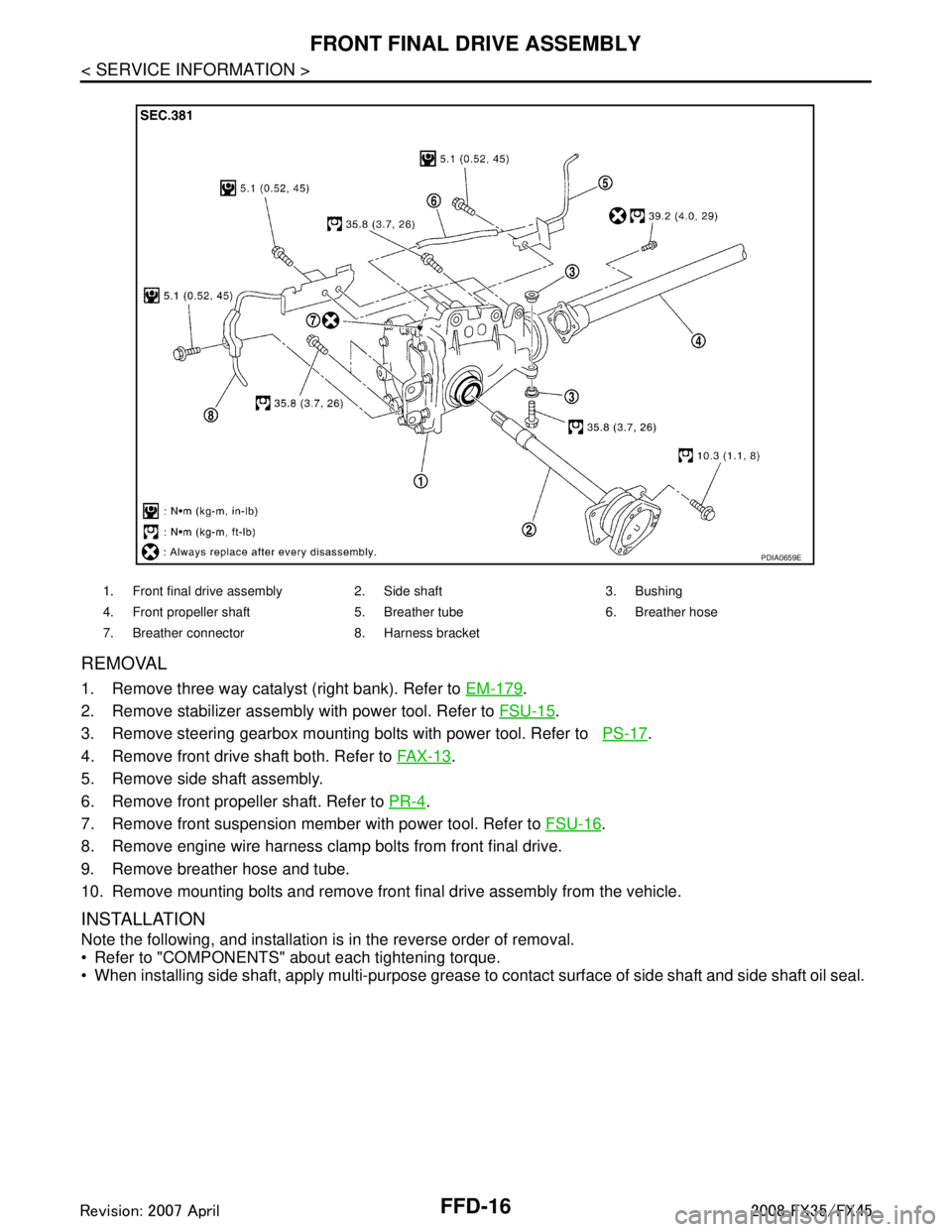
Refer to "COMPONENTS" about each tightening torque.
When installing side shaft, apply multi-purpose grease to contact surface of side shaft and side shaft oil seal.
1. Front final drive assembly 2. Side shaft 3. Bushing
4. Front propeller shaft 5. Breather tube 6. Breather hose
7. Breather connector 8. Harness bracket
PDIA0659E
3AA93ABC3ACD3AC03ACA3AC03AC63AC53A913A773A893A873A873A8E3A773A983AC73AC93AC03AC3
3A893A873A873A8F3A773A9D3AAF3A8A3A8C3A863A9D3AAF3A8B3A8C
Page 2833 of 3924
FL-1
ENGINE
C
DE
F
G H
I
J
K L
M
SECTION FL
A
FL
N
O P
CONTENTS
FUEL SYSTEM
SERVICE INFORMATION .. ..........................2
PREPARATION .............................................. .....2
Commercial Service Tool .................................... ......2
FUEL SYSTEM ....................................................3
Checking Fuel Line ............................................. ......3
General Precaution ...................................................3
FUEL LEVEL SENSOR UNIT, FUEL FILTER
AND FUEL PUMP ASSEMBLY ..........................
4
Component .......................................................... ......4
Removal and Installation ..................................... .....4
Component ...............................................................8
Disassembly and Assembly ......................................8
FUEL TANK ..................................... .................10
Component .......................................................... ....10
Removal and Installation .........................................10
SERVICE DATA AND SPECIFICATIONS
(SDS) .................................................................
12
Standard and Limit ..................................................12
3AA93ABC3ACD3AC03ACA3AC03AC63AC53A913A773A893A873A873A8E3A773A983AC73AC93AC03AC3
3A893A873A873A8F3A773A9D3AAF3A8A3A8C3A863A9D3AAF3A8B3A8C
Page 2835 of 3924
FUEL SYSTEMFL-3
< SERVICE INFORMATION >
C
DE
F
G H
I
J
K L
M A
FL
NP
O
FUEL SYSTEM
Checking Fuel LineINFOID:0000000001327104
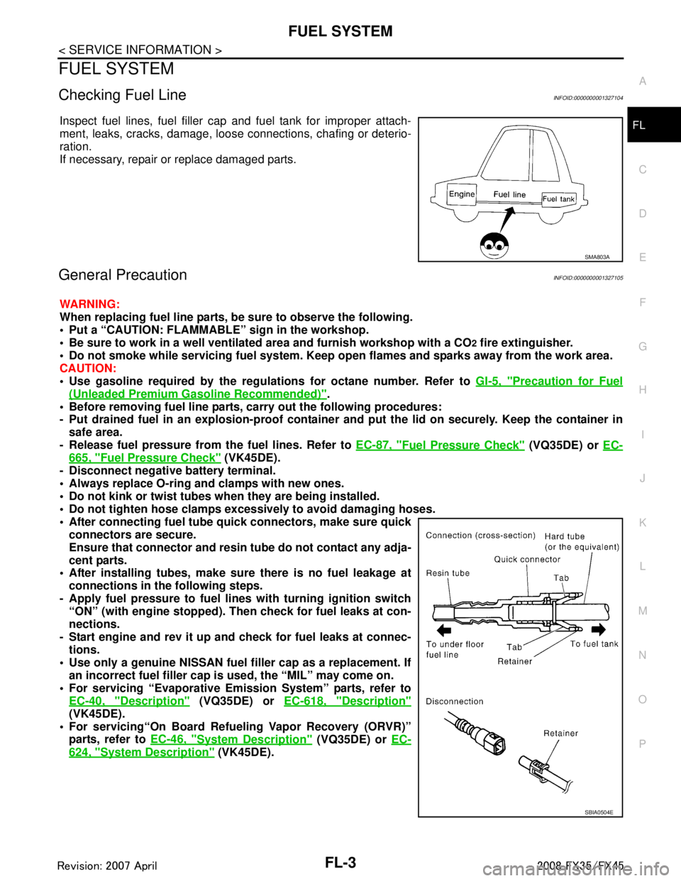
Inspect fuel lines, fuel filler cap and fuel tank for improper attach-
ment, leaks, cracks, damage, loos
e connections, chafing or deterio-
ration.
If necessary, repair or replace damaged parts.
General PrecautionINFOID:0000000001327105
WARNING:
When replacing fuel line parts, be sure to observe the following.
• Put a “CAUTION: FLAMMABLE” sign in the workshop.
Be sure to work in a well ventila ted area and furnish workshop with a CO
2 fire extinguisher.
Do not smoke while servicing fuel system. Keep open flames and sparks away from the work area.
CAUTION:
Use gasoline required by the regulations for octane number. Refer to GI-5, "
Precaution for Fuel
(Unleaded Premium Gasoline Recommended)".
Before removing fuel line parts, carry out the following procedures:
- Put drained fuel in an explosion-proof containe r and put the lid on securely. Keep the container in
safe area.
- Release fuel pressure from th e fuel lines. Refer to EC-87, "
Fuel Pressure Check" (VQ35DE) or EC-
665, "Fuel Pressure Check" (VK45DE).
- Disconnect negative battery terminal.
Always replace O-ring and clamps with new ones.
Do not kink or twist tubes when they are being installed.
Do not tighten hose clamps excessi vely to avoid damaging hoses.
After connecting fuel tube qu ick connectors, make sure quick
connectors are secure.
Ensure that connector and resin tube do not contact any adja-
cent parts.
After installing tubes, make su re there is no fuel leakage at
connections in the following steps.
- Apply fuel pressure to fuel li nes with turning ignition switch
“ON” (with engine stopped). Th en check for fuel leaks at con-
nections.
- Start engine and rev it up and check for fuel leaks at connec- tions.
Use only a genuine NISSAN fuel filler cap as a replacement. If
an incorrect fuel filler cap is used, the “MIL” may come on.
For servicing “Evaporative Emi ssion System” parts, refer to
EC-40, "
Description" (VQ35DE) or EC-618, "Description"
(VK45DE).
For servicing“On Board Refueling Vapor Recovery (ORVR)”
parts, refer to EC-46, "
System Description" (VQ35DE) or EC-
624, "System Description" (VK45DE).
SMA803A
SBIA0504E
3AA93ABC3ACD3AC03ACA3AC03AC63AC53A913A773A893A873A873A8E3A773A983AC73AC93AC03AC3
3A893A873A873A8F3A773A9D3AAF3A8A3A8C3A863A9D3AAF3A8B3A8C
Page 2840 of 3924
FL-8
< SERVICE INFORMATION >
FUEL LEVEL SENSOR UNIT, FUEL FILTER AND FUEL PUMP ASSEMBLY
1. Turn ignition switch “ON” (with engine stopped), then check connections for leaks by applying fuel pres-
sure to fuel piping.
2. Start engine and let it idle and make sure there are no fuel leaks at the fuel system connections.
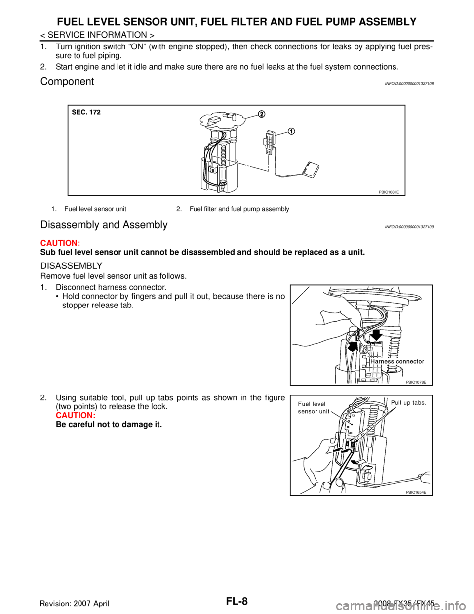
ComponentINFOID:0000000001327108
Disassembly and AssemblyINFOID:0000000001327109
CAUTION:
Sub fuel level sensor unit cannot be disassembled and should be replaced as a unit.
DISASSEMBLY
Remove fuel level sensor unit as follows.
1. Disconnect harness connector.
Hold connector by fingers and pull it out, because there is no
stopper release tab.
2. Using suitable tool, pull up tabs points as shown in the figure (two points) to release the lock.
CAUTION:
Be careful not to damage it.
1. Fuel level sensor unit 2. Fuel filter and fuel pump assembly
PBIC1081E
PBIC1078E
PBIC1654E
3AA93ABC3ACD3AC03ACA3AC03AC63AC53A913A773A893A873A873A8E3A773A983AC73AC93AC03AC3
3A893A873A873A8F3A773A9D3AAF3A8A3A8C3A863A9D3AAF3A8B3A8C
Page 2843 of 3924
FUEL TANKFL-11
< SERVICE INFORMATION >
C
DE
F
G H
I
J
K L
M A
FL
NP
O
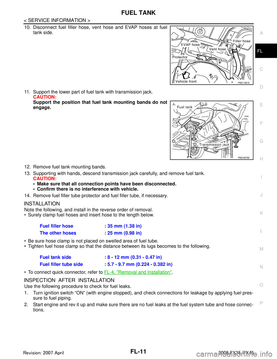
10. Disconnect fuel filler hose, v
ent hose and EVAP hoses at fuel
tank side.
11. Support the lower part of fuel tank with transmission jack. CAUTION:
Support the position that fuel tank mounting bands do not
engage.
12. Remove fuel tank mounting bands.
13. Supporting with hands, descend transmission jack carefully, and remove fuel tank. CAUTION:
Make sure that all connection points have been disconnected.
Confirm there is no interference with vehicle.
14. Remove fuel filler tube protector and fuel filler tube, if necessary.
INSTALLATION
Note the following, and install in the reverse order of removal.
Surely clamp fuel hoses and insert hose to the length below.
Be sure hose clamp is not placed on swelled area of fuel tube.
Tighten fuel hose clamp so that the distance between its lugs becomes to the following.
To connect quick connector, refer to FL-4, "
Removal and Installation".
INSPECTION AFTER INSTALLATION
Use the following procedure to check for fuel leaks.
1. Turn ignition switch “ON” (with engine stopped), and check connections for leakage by applying fuel pres-
sure to fuel piping.
2. Start engine and rev it up and make sure there are no fuel leaks at the fuel system tube and hose connec-
tions.
PBIC1581E
PBIC0878E
Fuel filler hose : 35 mm (1.38 in)
The other hoses : 25 mm (0.98 in)
Fuel tank side : 8 - 12 mm (0.31 - 0.47 in)
Fuel filler tube side : 5.7 - 9.7 mm (0.224 - 0.382 in)
3AA93ABC3ACD3AC03ACA3AC03AC63AC53A913A773A893A873A873A8E3A773A983AC73AC93AC03AC3
3A893A873A873A8F3A773A9D3AAF3A8A3A8C3A863A9D3AAF3A8B3A8C
Page 2846 of 3924
FSU-2
< SERVICE INFORMATION >
PRECAUTIONS
SERVICE INFORMATION
PRECAUTIONS
CautionINFOID:0000000001327533
• When installing rubber bushings, final tightening must be carried out under unladen conditions with tires on
ground. Oil will shorten the life of rubber bushings. Be sure to wipe off any spilled oil.
Unladen conditions mean that fuel, engine coolant and l ubricant are full. Spare tire, jack, hand tools and
mats are in designated positions.
After servicing suspension parts, be sure to check wheel alignment.
Caulking nuts are not reusable. Always use new ones w hen installing. Since new caulking nuts are pre-oiled,
tighten as they are.
Avoid burden to front cross bar.
3AA93ABC3ACD3AC03ACA3AC03AC63AC53A913A773A893A873A873A8E3A773A983AC73AC93AC03AC3
3A893A873A873A8F3A773A9D3AAF3A8A3A8C3A863A9D3AAF3A8B3A8C
Page 2849 of 3924

FRONT SUSPENSION ASSEMBLYFSU-5
< SERVICE INFORMATION >
C
DF
G H
I
J
K L
M A
B
FSU
N
O P
FRONT SUSPENSION ASSEMBLY
On-Vehicle Inspection and ServiceINFOID:0000000001327537
Make sure the mounting conditions (looseness, back lash) of each component and component conditions
(wear, damage) are normal.
INSPECTION LOWER BALL JOINT END PLAY
1. Set front wheels in a straight-ahead position. Do not depress brake pedal.
2. Place an iron bar or similar tool bet ween transverse link and steering knuckle.
3. Measure axial end play by prying it up and down.
CAUTION:
Be careful not to damage ball joint boot.
STRUT INSPECTION
Check strut for oil leakage, damage and replace if there are. Refer to FSU-10.
Wheel Alignment InspectionINFOID:0000000001327538
DESCRIPTION
Measure wheel alignment under unladen conditions.
NOTE:
Unladen conditions mean that fuel, engine coolant, and l ubricant are full. Spare tire, jack, hand tools and
mats are designated positions.
PRELIMINARY CHECK
Check tires for improper air pressure and wear.
Check road wheels for runout.
Check wheel bearing axial end play.
Check ball joint axial end play of compression rod, upper link, and steering knuckle
Check shock absorber operation.
Check each mounting part of axle and suspension for looseness and deformation.
Check each link, rod and member for cracks, deformation and other damage.
Check vehicle posture.
GENERAL INFORMATION AND RECOMMENDATIONS
A four-wheel thrust alignment should be performed.
- This type of alignment is recomm ended for any NISSAN/INFINITI vehicle.
- The four-wheel “thrust” process helps ensure that t he vehicle is properly aligned and the steering wheel is
centered.
- The alignment rack itself should be capable of accepting any NISSAN/INFINITI vehicle.
- The rack should be checked to ensure that it is level.
Make sure the machine is properly calibrated.
- Your alignment equipment should be regularly ca librated in order to give correct information.
- Check with the manufacturer of your specific equi pment for their recommended Service/Calibration Sched-
ule.
THE ALIGNMENT PROCESS
IMPORTANT:
Use only the alignment specificati ons listed in this Service Manual.
When displaying the alignment settings, many alignment machines use “indicators”: (Green/red, plus or
minus, Go/No Go). Do NOT use these indicators.
- The alignment specifications programmed into your machine that operate these indicators may not be cor-
rect.
- This may result in an ERROR.
Some newer alignment machines are equipped with an optional “Rolling Compensation” method to “com-
pensate” the sensors (alignment targets or head units). DO NOT use this “Rolling Compensation”
method. Axial end play : 0 mm (0 in)
3AA93ABC3ACD3AC03ACA3AC03AC63AC53A913A773A893A873A873A8E3A773A983AC73AC93AC03AC3
3A893A873A873A8F3A773A9D3AAF3A8A3A8C3A863A9D3AAF3A8B3A8C