2008 INFINITI FX35 u1000
[x] Cancel search: u1000Page 3050 of 3924
![INFINITI FX35 2008 Service Manual
LAN-30
< SERVICE INFORMATION >[CAN FUNDAMENTAL]
TROUBLE DIAGNOSES WORK FLOW
c. Reception item of “TCM”: “VDC/TCS/ABS”, “3” is
indicated in the “PAST”. This means TCM could not
receiv INFINITI FX35 2008 Service Manual
LAN-30
< SERVICE INFORMATION >[CAN FUNDAMENTAL]
TROUBLE DIAGNOSES WORK FLOW
c. Reception item of “TCM”: “VDC/TCS/ABS”, “3” is
indicated in the “PAST”. This means TCM could not
receiv](/manual-img/42/57017/w960_57017-3049.png)
LAN-30
< SERVICE INFORMATION >[CAN FUNDAMENTAL]
TROUBLE DIAGNOSES WORK FLOW
c. Reception item of “TCM”: “VDC/TCS/ABS”, “3” is
indicated in the “PAST”. This means TCM could not
receive the signal from ABS in the past. Draw a line between TCM and ABS (line 2-c in the figure below).
3. CAN DIAG SUPPORT MNTR (without PAST): Chec k the CAN DIAG SUPPORT MNTR (without PAST) of
units indicating “U1000” or “U1001” on SELF-DIAG RESULTS. Draw a line on the diagnosis sheet to indi-
cate the possible error circuit.
NOTE:
While an error occurred in the past according to SE LF-DIAG RESULTS, it is unclear which signal is not
received. Assume that errors were detected from all reception items.
Draw a single line among the unit and all reception it ems. (Work flow differs from CAN DIAG SUPPORT
MNTR (with PAST).)
a. Reception item of “EPS”: Assume that the unit could not receive the signals from ECM, ABS, and M&A.
Draw a line among EPS, ECM, ABS, and M&A (line 3-a in the figure below).
PKID1222E
3AA93ABC3ACD3AC03ACA3AC03AC63AC53A913A773A893A873A873A8E3A773A983AC73AC93AC03AC3
3A893A873A873A8F3A773A9D3AAF3A8A3A8C3A863A9D3AAF3A8B3A8C
Page 3054 of 3924
![INFINITI FX35 2008 Service Manual
LAN-34
< SERVICE INFORMATION >[CAN FUNDAMENTAL]
TROUBLE DIAGNOSES WORK FLOW
7. Perform the inspection procedure for the possible cause. Refer to
LAN-68, "Malfunction Area Chart".
Past Error — Shor INFINITI FX35 2008 Service Manual
LAN-34
< SERVICE INFORMATION >[CAN FUNDAMENTAL]
TROUBLE DIAGNOSES WORK FLOW
7. Perform the inspection procedure for the possible cause. Refer to
LAN-68, "Malfunction Area Chart".
Past Error — Shor](/manual-img/42/57017/w960_57017-3053.png)
LAN-34
< SERVICE INFORMATION >[CAN FUNDAMENTAL]
TROUBLE DIAGNOSES WORK FLOW
7. Perform the inspection procedure for the possible cause. Refer to
LAN-68, "Malfunction Area Chart".
Past Error — Short Circuit —
When the symptoms listed below exist, a short circuit of the CAN communication line is a possible cause.
PKID1224E
Item (CONSULT-III) Indication Inspection procedure
SELF-DIAG RESULTS “U1000” and “U1001” is indicated in the past for most units. Refer to LAN-68, "
Malfunction
Area Chart".
CAN DIAG SUPPORT MNTR Only on CAN DIAG SUPPORT MNTR (with PAST), “1 - 39” is in-
dicated on “PAST” of “TRANSMIT DIAG” and the reception item.
3AA93ABC3ACD3AC03ACA3AC03AC63AC53A913A773A893A873A873A8E3A773A983AC73AC93AC03AC3
3A893A873A873A8F3A773A9D3AAF3A8A3A8C3A863A9D3AAF3A8B3A8C
Page 3056 of 3924
![INFINITI FX35 2008 Service Manual
LAN-36
< SERVICE INFORMATION >[CAN]
INDEX FOR DTC
SERVICE INFORMATION
INDEX FOR DTC
DTC No. IndexINFOID:0000000001328627
DTCSelf-diagnosis item
(CONSULT-III indication) DTC detection condition Inspe INFINITI FX35 2008 Service Manual
LAN-36
< SERVICE INFORMATION >[CAN]
INDEX FOR DTC
SERVICE INFORMATION
INDEX FOR DTC
DTC No. IndexINFOID:0000000001328627
DTCSelf-diagnosis item
(CONSULT-III indication) DTC detection condition Inspe](/manual-img/42/57017/w960_57017-3055.png)
LAN-36
< SERVICE INFORMATION >[CAN]
INDEX FOR DTC
SERVICE INFORMATION
INDEX FOR DTC
DTC No. IndexINFOID:0000000001328627
DTCSelf-diagnosis item
(CONSULT-III indication) DTC detection condition Inspection
U1000 CAN COMM CIRCUIT When ECM is not transmitting or receiving CAN
communication signal of OBD (emission-related
diagnosis) for 2 seconds or more.
Refer to LAN-37
.
When a control unit (except for ECM) is not
transmitting or receiving CAN communication
signal for 2 seconds or more.
U1001 CAN COMM CIRCUIT When ECM is not transmitting or receiving CAN
communication signal other than OBD (emis-
sion-related diagnosis) for 2 seconds or more.
U1002 SYSTEM COMM When a control unit is not transmitting or receiv-
ing CAN communication signal for 2 seconds or
less. Start the inspection. Re-
fer to the applicable sec-
tion of the indicated
control unit.
U1010 CONTROL UNIT [CAN] When an error is detected during the initial diag-
nosis for CAN controller of each control unit. Replace the control unit
indicating “U1010”.
3AA93ABC3ACD3AC03ACA3AC03AC63AC53A913A773A893A873A873A8E3A773A983AC73AC93AC03AC3
3A893A873A873A8F3A773A9D3AAF3A8A3A8C3A863A9D3AAF3A8B3A8C
Page 3148 of 3924

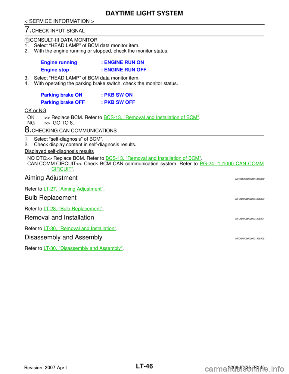
LT-46
< SERVICE INFORMATION >
DAYTIME LIGHT SYSTEM
7.CHECK INPUT SIGNAL
CONSULT-III DATA MONITOR
1. Select “HEAD LAMP” of BCM data monitor item.
2. With the engine running or stopped, check the monitor status.
3. Select “HEAD LAMP” of BCM data monitor item.
4. With operating the parking brake switch, check the monitor status.
OK or NG
OK >> Replace BCM. Refer to BCS-13, "Removal and Installation of BCM".
NG >> GO TO 8.
8.CHECKING CAN COMMUNICATIONS
1. Select “self-diagnosis” of BCM”.
2. Check display content in self-diagnosis results.
Displayed self
-diagnosis results
NO DTC>> Replace BCM. Refer to BCS-13, "Removal and Installation of BCM".
CAN COMM CIRCUIT>> Check BCM CAN communication system. Refer to PG-24, "
U1000 CAN COMM
CIRCUIT".
Aiming AdjustmentINFOID:0000000001328302
Refer to LT-27, "Aiming Adjustment".
Bulb ReplacementINFOID:0000000001328303
Refer to LT-28, "Bulb Replacement".
Removal and InstallationINFOID:0000000001328304
Refer to LT-30, "Removal and Installation".
Disassembly and AssemblyINFOID:0000000001328305
Refer to LT-30, "Disassembly and Assembly".
Engine running : ENGINE RUN ON
Engine stop : ENGINE RUN OFF
Parking brake ON : PKB SW ON
Parking brake OFF : PKB SW OFF
3AA93ABC3ACD3AC03ACA3AC03AC63AC53A913A773A893A873A873A8E3A773A983AC73AC93AC03AC3
3A893A873A873A8F3A773A9D3AAF3A8A3A8C3A863A9D3AAF3A8B3A8C
Page 3160 of 3924

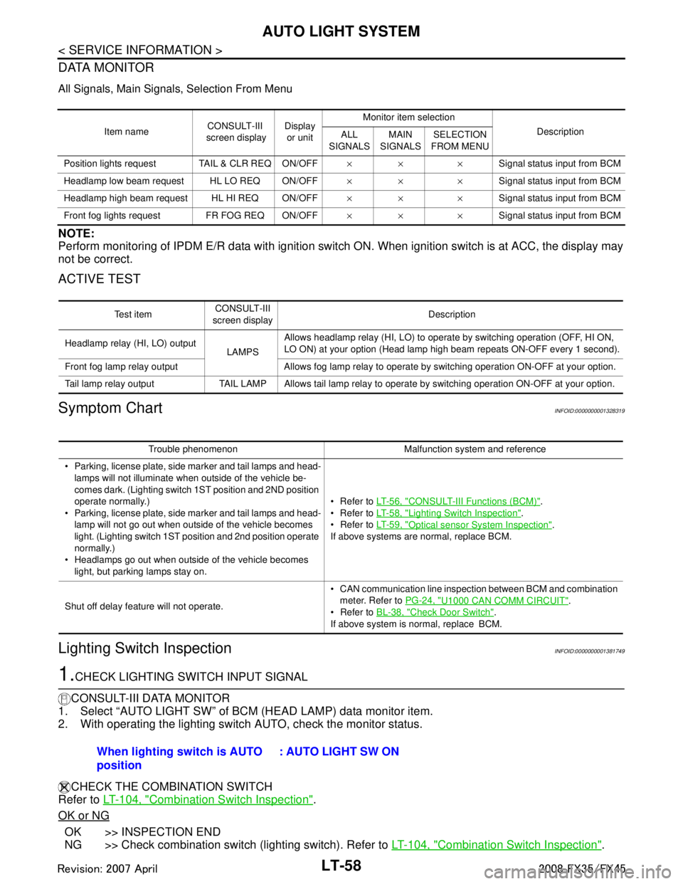
LT-58
< SERVICE INFORMATION >
AUTO LIGHT SYSTEM
DATA MONITOR
All Signals, Main Signals, Selection From Menu
NOTE:
Perform monitoring of IPDM E/R data with ignition switch ON. When ignition switch is at ACC, the display may
not be correct.
ACTIVE TEST
Symptom ChartINFOID:0000000001328319
Lighting Switch InspectionINFOID:0000000001381749
1.CHECK LIGHTING SWITCH INPUT SIGNAL
CONSULT-III DATA MONITOR
1. Select “AUTO LIGHT SW” of BCM (HEAD LAMP) data monitor item.
2. With operating the lighting switch AUTO, check the monitor status.
CHECK THE COMBINATION SWITCH
Refer to LT-104, "
Combination Switch Inspection".
OK or NG
OK >> INSPECTION END
NG >> Check combination switch (lighting switch). Refer to LT-104, "
Combination Switch Inspection".
Item nameCONSULT-III
screen display Display
or unit Monitor item selection
Description
ALL
SIGNALS MAIN
SIGNALS SELECTION
FROM MENU
Position lights reques t TAIL & CLR REQ ON/OFF ×× ×Signal status input from BCM
Headlamp low beam request HL LO REQ ON/OFF ×× ×Signal status input from BCM
Headlamp high beam request HL HI REQ ON/OFF ×× ×Signal status input from BCM
Front fog lights request FR FOG REQ ON/OFF ×× ×Signal status input from BCM
Te s t i t e mCONSULT-III
screen display Description
Headlamp relay (HI, LO) output LAMPSAllows headlamp relay (HI, LO) to operate by switching operation (OFF, HI ON,
LO ON) at your option (Head lamp high beam repeats ON-OFF every 1 second).
Front fog lamp relay output Allows fog lamp relay to operate by switching operation ON-OFF at your option.
Tail lamp relay output TAIL LAMP Allows tail lamp relay to operate by switching operation ON-OFF at your option.
Trouble phenomenon Malfunction system and reference
Parking, license plate, side marker and tail lamps and head- lamps will not illuminate when outside of the vehicle be-
comes dark. (Lighting switch 1ST position and 2ND position
operate normally.)
Parking, license plate, side marker and tail lamps and head-
lamp will not go out when outside of the vehicle becomes
light. (Lighting switch 1ST position and 2nd position operate
normally.)
Headlamps go out when outside of the vehicle becomes light, but parking lamps stay on. Refer to
LT- 5 6 , "
CONSULT-III Functions (BCM)".
Refer to LT- 5 8 , "
Lighting Switch Inspection".
Refer to LT- 5 9 , "
Optical sensor System Inspection".
If above systems are normal, replace BCM.
Shut off delay feature will not operate. CAN communication line inspection between BCM and combination
meter. Refer to PG-24, "
U1000 CAN COMM CIRCUIT".
Refer to BL-38, "
Check Door Switch".
If above system is normal, replace BCM.
When lighting switch is AUTO
position : AUTO LIGHT SW ON
3AA93ABC3ACD3AC03ACA3AC03AC63AC53A913A773A893A873A873A8E3A773A983AC73AC93AC03AC3
3A893A873A873A8F3A773A9D3AAF3A8A3A8C3A863A9D3AAF3A8B3A8C
Page 3365 of 3924

PG-1
ELECTRICAL
C
DE
F
G H
I
J
L
M
SECTION PG
A
B
PG
N
O P
CONTENTS
POWER SUPPLY, GROUND & CIRCUIT ELEMENTS
SERVICE INFORMATION .. ..........................2
DTC INDEX ..................................................... .....2
U1000 .................................................................. ......2
POWER SUPPLY ROUTING CIRCUIT ...............3
Schematic ........................................................... ......3
Wiring Diagram - POWER - ......................................4
Fuse ........................................................................16
Fusible Link .............................................................16
Circuit Breaker ........................................................16
IPDM E/R (INTELLIGENT POWER DISTRI-
BUTION MODULE ENGINE ROOM) .................
17
System Description ............................................. ....17
CAN Communication System Description ...............18
CAN Communication Unit .......................................18
Function of Detecting Ignition Relay Malfunction ....18
CONSULT-III Function (IPDM E/R) ..................... ....18
Auto Active Test ......................................................20
Schematic ...............................................................22
IPDM E/R Terminal Arrangement ...........................23
IPDM E/R Power/Ground Circuit Inspection ...........23
U1000 CAN COMM CIRCUIT .................................24
Removal and Installation of IPDM E/R ....................24
GROUND ...........................................................26
Ground Distribution .............................................. ....26
HARNESS .........................................................40
Harness Layout ................................................... ....40
Wiring Diagram Codes (Cell Codes) .......................60
ELECTRICAL UNITS LOCATION ....................64
Electrical Units Location ..........................................64
HARNESS CONNECTOR .................................68
Description ...............................................................68
ELECTRICAL UNITS ........................................71
Terminal Arrangement .............................................71
SMJ (SUPER MULTIPLE JUNCTION) .............73
Terminal Arrangement .............................................73
STANDARDIZED RELAY .................................75
Description ...............................................................75
FUSE BLOCK - JUNCTION BOX (J/B) ............77
Terminal Arrangement .............................................77
FUSE, FUSIBLE LINK AND RELAY BOX ........78
Terminal Arrangement .............................................78
3AA93ABC3ACD3AC03ACA3AC03AC63AC53A913A773A893A873A873A8E3A773A983AC73AC93AC03AC3
3A893A873A873A8F3A773A9D3AAF3A8A3A8C3A863A9D3AAF3A8B3A8C
Page 3366 of 3924

PG-2
< SERVICE INFORMATION >
DTC INDEX
SERVICE INFORMATION
DTC INDEX
U1000INFOID:0000000001351918
DTC Items (CONSULT screen terms) Reference
U1000 CAN COMM CIRCUIT PG-24, "
U1000 CAN COMM CIRCUIT"
3AA93ABC3ACD3AC03ACA3AC03AC63AC53A913A773A893A873A873A8E3A773A983AC73AC93AC03AC3
3A893A873A873A8F3A773A9D3AAF3A8A3A8C3A863A9D3AAF3A8B3A8C
Page 3383 of 3924

IPDM E/R (INTELLIGENT POWER DISTRIBUTION MODULE ENGINE ROOM)
PG-19
< SERVICE INFORMATION >
C
D E
F
G H
I
J
L
M A
B
PG
N
O P
NOTE: The details for display of the period are as follows:
CRNT: Error currently de tected with IPDM E/R.
PAST: Error detected in the past and memorized with IPDM E/R.
DATA MONITOR
NOTE:
Perform monitoring of IPDM E/R data with the ignition switch ON. When the ignition switch is at ACC, the display may not be co rrect.
*1: The vehicle without the Intelligent Key system displays only ON without change.
*2:The cornering lamp item is displayed, but it cannot be monitored.
ACTIVE TEST
DTC Display Items Malfunction detecting condition TIME
Possible causes
CRNT PAST
— NO DTC IS DETECT-
ED.FURTHER TEST-
ING MAY BE
REQUIRED. ————
U1000 CAN COMM CIRCUIT If CAN communication reception/transmission
data has a malfunction, or if any of the control
units malfunction, data reception/transmission
cannot be confirmed.
When the data in CAN communication is not re- ceived before the specified time ××
Any of or several items
below have errors.
TRANSMIT DIAG
ECM
BCM/SEC
Item name
CONSULT-III screen dis-
play Display or unit MAIN SIG-
NALS Description
Motor fan request MOTOR FAN REQ 1/2/3/4 ×Signal status input from ECM
Compressor request A C COMP REQ On/Off ×Signal status input from ECM
Tail & clear request TAIL&CLR REQ On/Off ×Signal status input from BCM
H/L LO request HL LO REQ On/Off ×Signal status input from BCM
H/L HI request HL HI REQ On/Off ×Signal status input from BCM
FR fog request FR FOG REQ On/Off ×Signal status input from BCM
FR wiper request FR WIP REQ Stop/1LOW/Lo/Hi ×Signal status input from BCM
Wiper auto stop WIP AUTO STOP ACT P/STOP P ×Output status of IPDM E/R
Wiper protection WIP PROT Off/BLOCK ×Control status of IPDM E/R
Starter request ST RLY REQ
*1On/Off Status of input signal
Ignition relay status IGN RLY On/Off ×Ignition relay status monitored with
IPDM E/R
Rear window defogger re-
quest RR DEF REQ On/Off
×Signal status input from BCM
Oil pressure switch OIL P SW Open/Close Signal status input in IPDM E/R
Hood switch HOOD SW On/Off Input signal status
Theft warning horn re-
quest THFT HRN REQ On/Off Signal st
atus input from BCM
Horn chirp HORN CHIRP On/Off Ou tput status of IPDM E/R
Cornering lamp request CRNRNG LMP REQ
*2Off Signal status input from BCM
Test item CONSULT-III screen display Description
Tail lamp operation TAIL LAMP With a certain On-Off operation, the tail lamp relay can be operated.
Rear window defogger opera-
tion REAR DEFOGGER
With a certain On-Off operation, the rear window defogger relay can be
operated.
3AA93ABC3ACD3AC03ACA3AC03AC63AC53A913A773A893A873A873A8E3A773A983AC73AC93AC03AC3
3A893A873A873A8F3A773A9D3AAF3A8A3A8C3A863A9D3AAF3A8B3A8C