2008 INFINITI FX35 height
[x] Cancel search: heightPage 2822 of 3924
FRONT FINAL DRIVE ASSEMBLYFFD-31
< SERVICE INFORMATION >
CEF
G H
I
J
K L
M A
B
FFD
N
O P
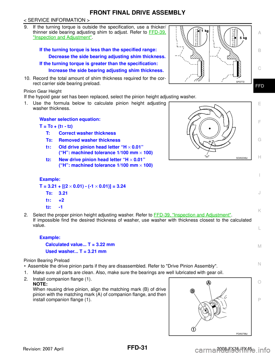
9. If the turning torque is outside the specification, use a thicker/ thinner side bearing adjusting shim to adjust. Refer to FFD-39,
"Inspection and Adjustment".
10. Record the total amount of shim thickness required for the cor- rect carrier side bearing preload.
Pinion Gear Height
If the hypoid gear set has been replaced, se lect the pinion height adjusting washer.
1. Use the formula below to calculate pinion height adjusting washer thickness.
2. Select the proper pinion height adjusting washer. Refer to FFD-39, "
Inspection and Adjustment".
If impossible find the desired thickness of washer, us e washer with thickness closest to the calculated
value.
Pinion Bearing Preload
Assemble the drive pinion parts if they are disassembled. Refer to "Drive Pinion Assembly".
1. Make sure all parts are clean. Also, make sure the bearings are well lubricated with gear oil.
2. Install companion flange (1). NOTE:
When reusing drive pinion, align the matching mark (B) of drive
pinion with the matching mark (A) of companion flange, and then
install companion flange (1).If the turning torque is l
ess than the specified range:
Decrease the side bearing adjusting shim thickness.
If the turning torque is gr eater than the specification:
Increase the side bearing adjusting shim thickness.
SPD772
Washer selection equation:
T = T
0 + (t1 - t2)
T: Correct washer thickness
T
0: Removed washer thickness
t
1: Old drive pinion head letter “H × 0.01”
(“H”: machined tolerance 1/100 mm × 100)
t
2: New drive pinion head letter “H × 0.01”
(“H”: machined tolerance 1/100 mm × 100)
Example:
T = 3.21 + [(2 × 0.01) - (-1 × 0.01)] = 3.24
T
0:3.21
t
1:+2
t
2:-1
Example: Calculated value... T = 3.22 mm
Used washer... T = 3.21 mm
SDIA0249J
PDIA0799J
3AA93ABC3ACD3AC03ACA3AC03AC63AC53A913A773A893A873A873A8E3A773A983AC73AC93AC03AC3
3A893A873A873A8F3A773A9D3AAF3A8A3A8C3A863A9D3AAF3A8B3A8C
Page 2824 of 3924
FRONT FINAL DRIVE ASSEMBLYFFD-33
< SERVICE INFORMATION >
CEF
G H
I
J
K L
M A
B
FFD
N
O P
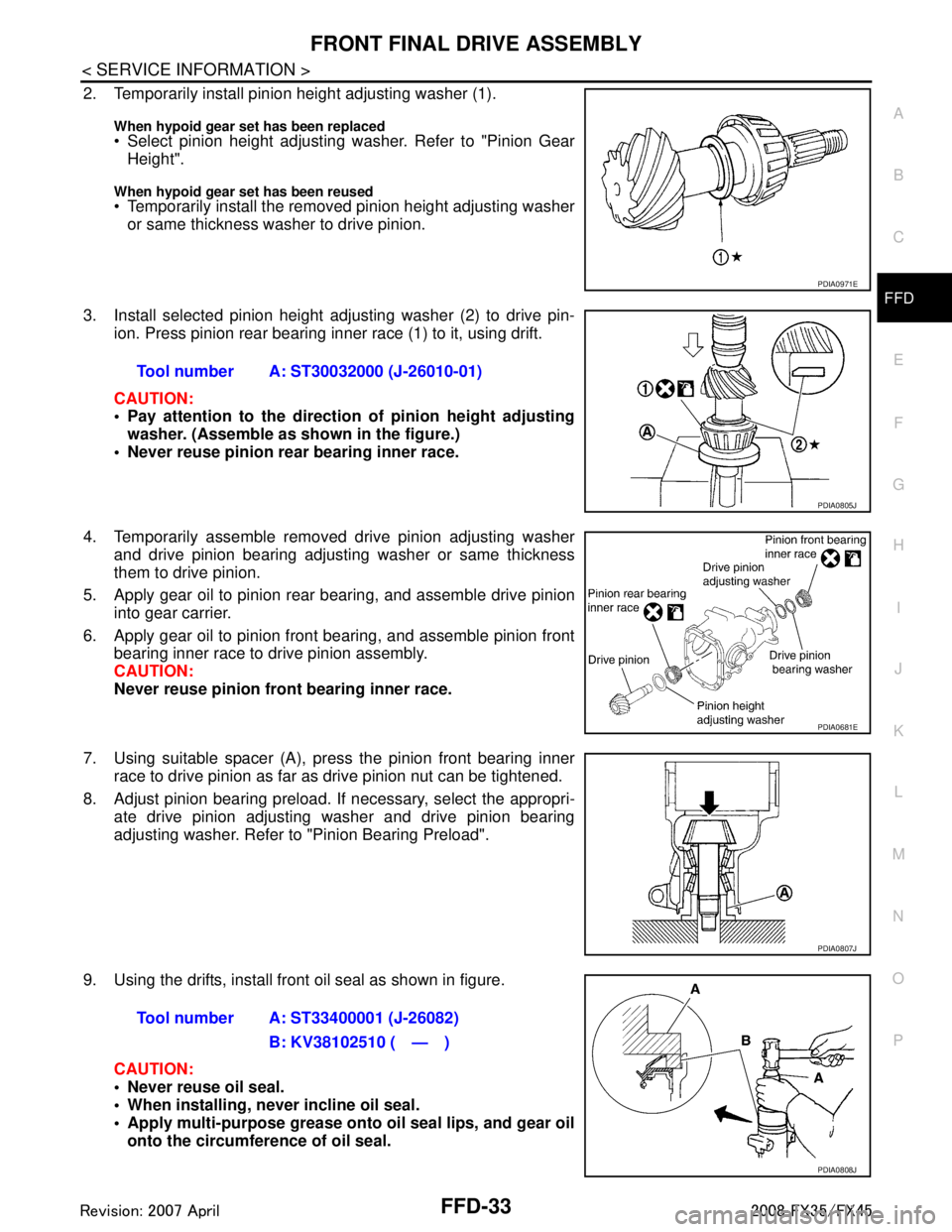
2. Temporarily install pinion height adjusting washer (1).
When hypoid gear se t has been replaced Select pinion height adjusting washer. Refer to "Pinion Gear
Height".
When hypoid gear set has been reused Temporarily install the removed pinion height adjusting washer
or same thickness washer to drive pinion.
3. Install selected pinion height adjusting washer (2) to drive pin- ion. Press pinion rear bearing inner race (1) to it, using drift.
CAUTION:
Pay attention to the direction of pinion height adjusting
washer. (Assemble as shown in the figure.)
Never reuse pinion rear bearing inner race.
4. Temporarily assemble removed drive pinion adjusting washer and drive pinion bearing adjusting washer or same thickness
them to drive pinion.
5. Apply gear oil to pinion rear bearing, and assemble drive pinion into gear carrier.
6. Apply gear oil to pinion front bearing, and assemble pinion front bearing inner race to drive pinion assembly.
CAUTION:
Never reuse pinion front bearing inner race.
7. Using suitable spacer (A), press the pinion front bearing inner race to drive pinion as far as drive pinion nut can be tightened.
8. Adjust pinion bearing preload. If necessary, select the appropri- ate drive pinion adjusting washer and drive pinion bearing
adjusting washer. Refer to "Pinion Bearing Preload".
9. Using the drifts, install front oil seal as shown in figure. CAUTION:
Never reuse oil seal.
When installing, never incline oil seal.
Apply multi-purpose grease onto oil seal lips, and gear oilonto the circumference of oil seal.
PDIA0971E
Tool number A: ST30032000 (J-26010-01)
PDIA0805J
PDIA0681E
PDIA0807J
Tool number A: ST33400001 (J-26082)
B: KV38102510 ( — )
PDIA0808J
3AA93ABC3ACD3AC03ACA3AC03AC63AC53A913A773A893A873A873A8E3A773A983AC73AC93AC03AC3
3A893A873A873A8F3A773A9D3AAF3A8A3A8C3A863A9D3AAF3A8B3A8C
Page 2831 of 3924
FFD-40
< SERVICE INFORMATION >
SERVICE DATA AND SPECIFICATIONS (SDS)
Unit: mm (in)
*: Always check with the Parts Department for the latest parts information.
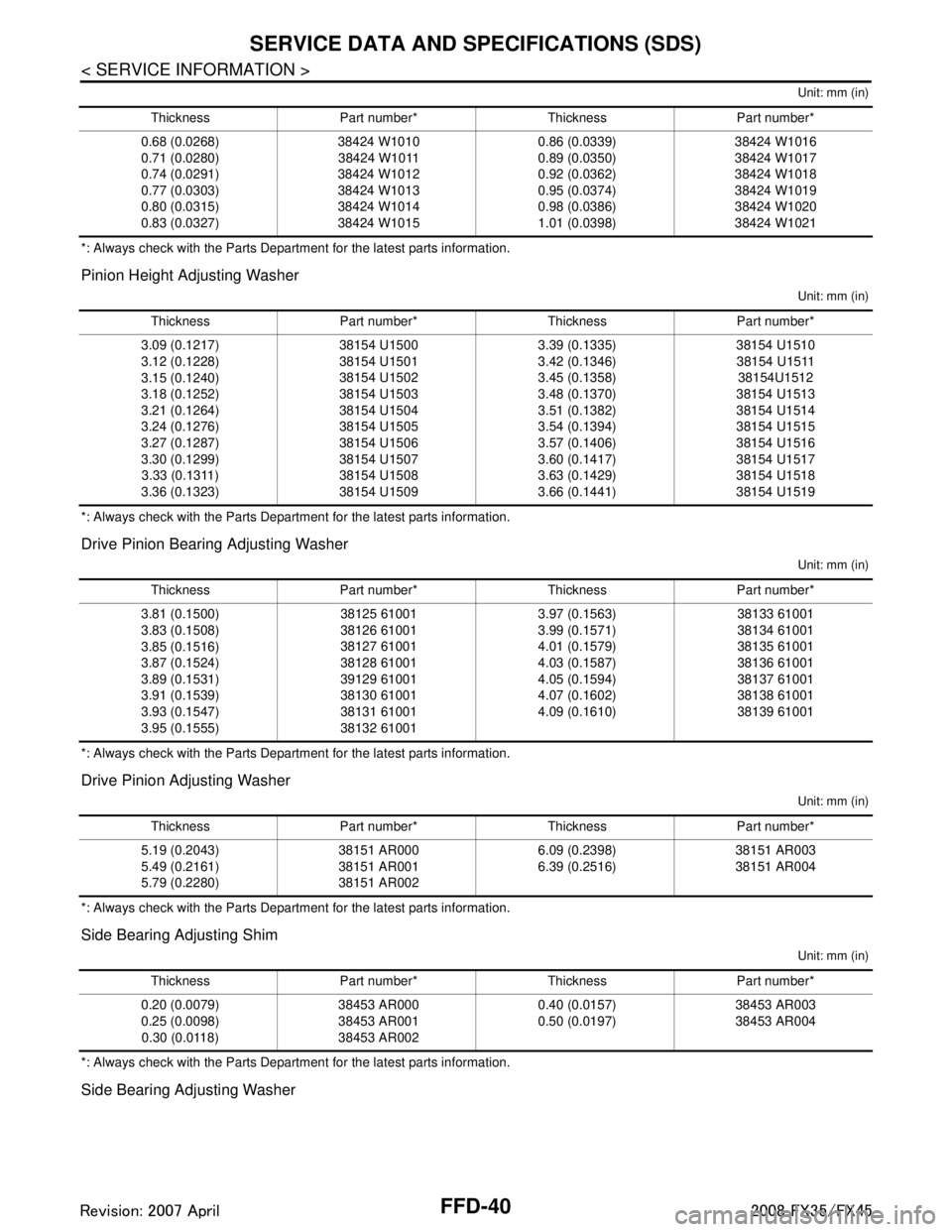
Pinion Height Adjusting Washer
Unit: mm (in)
*: Always check with the Parts Department for the latest parts information.
Drive Pinion Bearing Adjusting Washer
Unit: mm (in)
*: Always check with the Parts Department for the latest parts information.
Drive Pinion Adjusting Washer
Unit: mm (in)
*: Always check with the Parts Department for the latest parts information.
Side Bearing Adjusting Shim
Unit: mm (in)
*: Always check with the Parts Department for the latest parts information.
Side Bearing Adjusting Washer
Thickness Part number* Thickness Part number*
0.68 (0.0268)
0.71 (0.0280)
0.74 (0.0291)
0.77 (0.0303)
0.80 (0.0315)
0.83 (0.0327) 38424 W1010
38424 W1011
38424 W1012
38424 W1013
38424 W1014
38424 W1015 0.86 (0.0339)
0.89 (0.0350)
0.92 (0.0362)
0.95 (0.0374)
0.98 (0.0386)
1.01 (0.0398)38424 W1016
38424 W1017
38424 W1018
38424 W1019
38424 W1020
38424 W1021
Thickness Part number* Thickness Part number*
3.09 (0.1217)
3.12 (0.1228)
3.15 (0.1240)
3.18 (0.1252)
3.21 (0.1264)
3.24 (0.1276)
3.27 (0.1287)
3.30 (0.1299) 3.33 (0.1311)
3.36 (0.1323) 38154 U1500
38154 U1501
38154 U1502
38154 U1503
38154 U1504
38154 U1505
38154 U1506
38154 U1507
38154 U1508
38154 U1509 3.39 (0.1335)
3.42 (0.1346)
3.45 (0.1358)
3.48 (0.1370)
3.51 (0.1382)
3.54 (0.1394)
3.57 (0.1406)
3.60 (0.1417)
3.63 (0.1429)
3.66 (0.1441)38154 U1510
38154 U1511 38154U1512
38154 U1513
38154 U1514
38154 U1515
38154 U1516
38154 U1517
38154 U1518
38154 U1519
Thickness Part number* Thickness Part number*
3.81 (0.1500)
3.83 (0.1508)
3.85 (0.1516)
3.87 (0.1524)
3.89 (0.1531)
3.91 (0.1539)
3.93 (0.1547)
3.95 (0.1555) 38125 61001
38126 61001
38127 61001
38128 61001
39129 61001
38130 61001
38131 61001
38132 610013.97 (0.1563)
3.99 (0.1571)
4.01 (0.1579)
4.03 (0.1587)
4.05 (0.1594)
4.07 (0.1602)
4.09 (0.1610)
38133 61001
38134 61001
38135 61001
38136 61001
38137 61001
38138 61001
38139 61001
Thickness Part number* Thickness Part number*
5.19 (0.2043)
5.49 (0.2161)
5.79 (0.2280) 38151 AR000
38151 AR001
38151 AR002 6.09 (0.2398)
6.39 (0.2516)
38151 AR003
38151 AR004
Thickness Part number* Thickness Part number*
0.20 (0.0079)
0.25 (0.0098) 0.30 (0.0118) 38453 AR000
38453 AR001
38453 AR002 0.40 (0.0157)
0.50 (0.0197)
38453 AR003
38453 AR004
3AA93ABC3ACD3AC03ACA3AC03AC63AC53A913A773A893A873A873A8E3A773A983AC73AC93AC03AC3
3A893A873A873A8F3A773A9D3AAF3A8A3A8C3A863A9D3AAF3A8B3A8C
Page 2845 of 3924
FSU-1
SUSPENSION
C
DF
G H
I
J
K L
M
SECTION FSU
A
B
FSU
N
O PCONTENTS
FRONT SUSPENSION
SERVICE INFORMATION .. ..........................2
PRECAUTIONS .............................................. .....2
Caution ................................................................ ......2
PREPARATION ...................................................3
Special Service Tool ........................................... ......3
Commercial Service Tool ..........................................3
NOISE, VIBRATION AND HARSHNESS
(NVH) TROUBLESHOOTING .............................
4
NVH Troubleshooting Chart ................................ ......4
FRONT SUSPENSION ASSEMBLY ...................5
On-Vehicle Inspection and Service ..................... ......5
Wheel Alignment Inspection ......................................5
Removal and Installation ...........................................6
COIL SPRING AND STRUT ..............................10
Removal and Installation ..................................... ....10
Disassembly and Assembly .....................................11
TRANSVERSE LINK .........................................13
Removal and Installation ..................................... ....13
STABILIZER BAR .............................................15
Removal and Installation .........................................15
FRONT SUSPENSION MEMBER .....................16
Removal and Installation .........................................16
SERVICE DATA AND SPECIFICATIONS
(SDS) .................................................................
17
Wheel Alignment (Unladen*) ...................................17
Ball Joint ..................................................................17
Wheelarch Height (Unladen*) ..................................17
3AA93ABC3ACD3AC03ACA3AC03AC63AC53A913A773A893A873A873A8E3A773A983AC73AC93AC03AC3
3A893A873A873A8F3A773A9D3AAF3A8A3A8C3A863A9D3AAF3A8B3A8C
Page 2850 of 3924
FSU-6
< SERVICE INFORMATION >
FRONT SUSPENSION ASSEMBLY
- Use the “Jacking Compensation Method”. After installing the alignment targets or head units, raise the vehi-
cle and rotate the wheels 1/2 turn both ways.
- See Instructions in the alignment machine you're using for more information on this.
INSPECTION OF CAMBER, CASTER AND KINGPIN INCLINATION ANGLES
Camber, caster, kingpin inclination angles cannot be adjusted.
Before inspection, mount front wheels onto turning radius gauge. Mount rear wheels onto a stand that has
same height so vehicle will remain horizontal.
Removal and InstallationINFOID:0000000001327539
COMPONENTS
3AA93ABC3ACD3AC03ACA3AC03AC63AC53A913A773A893A873A873A8E3A773A983AC73AC93AC03AC3
3A893A873A873A8F3A773A9D3AAF3A8A3A8C3A863A9D3AAF3A8B3A8C
Page 2861 of 3924
SERVICE DATA AND SPECIFICATIONS (SDS)
FSU-17
< SERVICE INFORMATION >
C
D F
G H
I
J
K L
M A
B
FSU
N
O P
SERVICE DATA AND SPECIFICATIONS (SDS)
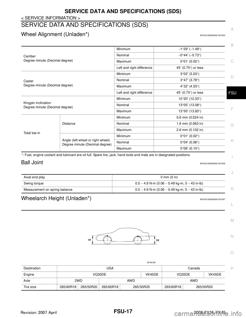
Wheel Alignment (Unladen*)INFOID:0000000001327545
*: Fuel, engine coolant and lubricant are oil full. Spare tire, jack, hand tools and mats are in designated positions.
Ball JointINFOID:0000000001327546
Wheelarch Height (Unladen*)INFOID:0000000001327547
Camber
Degree minute (Decimal degree) Minimum
−1 °29 ′ ( −1.48 °)
Nominal −0 °44 ′ ( −0.73 °)
Maximum 0 °01 ′ (0.02 °)
Left and right difference 45 ′ (0.75 °) or less
Caster
Degree minute (Decimal degree) Minimum 3
°02 ′ (3.03 °)
Nominal 3 °47 ′ (3.78 °)
Maximum 4 °32 ′ (4.53 °)
Left and right difference 45 ′ (0.75 °) or less
Kingpin inclination
Degree minute (Decimal degree) Minimum 12
°20 ′ (12.33 °)
Nominal 13 °05 ′ (13.08 °)
Maximum 13 °50 ′ (13.83 °)
Total toe-in Distance
Minimum 0.6 mm (0.024 in)
Nominal 1.6 mm (0.063 in)
Maximum 2.6 mm (0.102 in)
Angle (left wheel or right wheel)
Degree minute (Decimal degree) Minimum 0
°01 ′ (0.02 °)
Nominal 0
° 04 ′ (0.06 °)
Maximum 0 °06 ′ (0.10 °)
Axial end play 0 mm (0 in)
Swing torque 0.5 − 4.9 N·m (0.06 − 0.49 kg-m, 5 − 43 in-lb)
Measurement on spring balance 0.5 − 4.9 N·m (0.06 − 0.49 kg-m, 5 − 43 in-lb)
Destination USA Canada
Engine VQ35DE VK45DE VQ35DE VK45DE
Axle 2WD AWD AWD
Tire size 265/60R18 265/50R20 265/60R18 265/50R20 265/60R18 265/50R20
SFA818A
3AA93ABC3ACD3AC03ACA3AC03AC63AC53A913A773A893A873A873A8E3A773A983AC73AC93AC03AC3
3A893A873A873A8F3A773A9D3AAF3A8A3A8C3A863A9D3AAF3A8B3A8C
Page 2909 of 3924
IDENTIFICATION INFORMATIONGI-47
< SERVICE INFORMATION >
C
DE
F
G H
I
J
K L
M B
GI
N
O PAUTOMATIC TRANSMISSION NUMBER
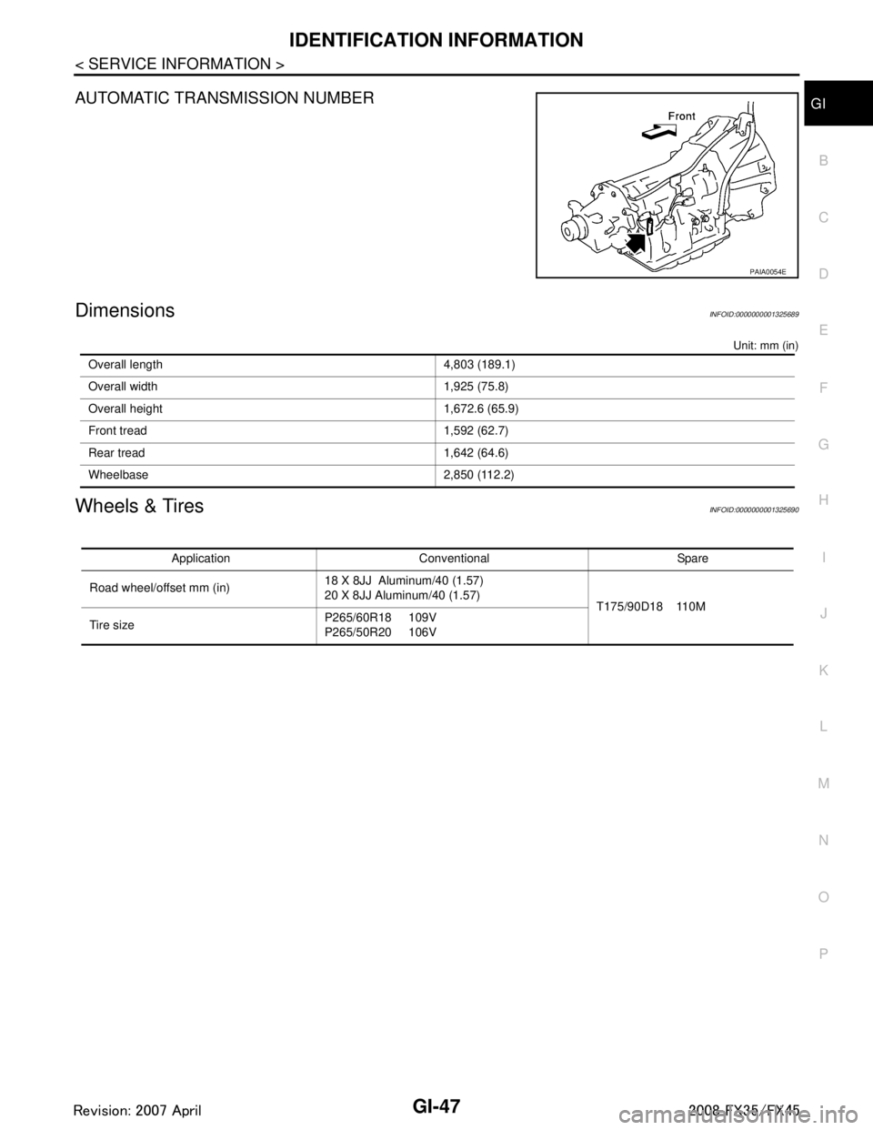
DimensionsINFOID:0000000001325689
Unit: mm (in)
Wheels & TiresINFOID:0000000001325690
PAIA0054E
Overall length 4,803 (189.1)
Overall width 1,925 (75.8)
Overall height 1,672.6 (65.9)
Front tread 1,592 (62.7)
Rear tread 1,642 (64.6)
Wheelbase 2,850 (112.2)
Application Conventional Spare
Road wheel/offset mm (in) 18 X 8JJ Aluminum/40 (1.57)
20 X 8JJ Aluminum/40 (1.57)
T175/90D18 110M
Tire size P265/60R18 109V
P265/50R20 106V
3AA93ABC3ACD3AC03ACA3AC03AC63AC53A913A773A893A873A873A8E3A773A983AC73AC93AC03AC3
3A893A873A873A8F3A773A9D3AAF3A8A3A8C3A863A9D3AAF3A8B3A8C
Page 3178 of 3924
LT-76
< SERVICE INFORMATION >
FRONT FOG LAMP
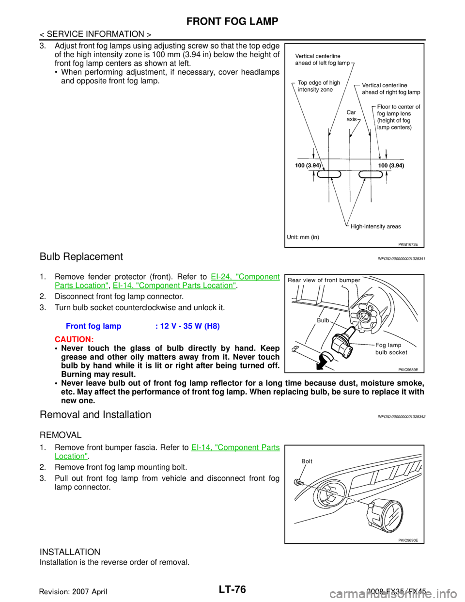
3. Adjust front fog lamps using adjusting screw so that the top edgeof the high intensity zone is 100 mm (3.94 in) below the height of
front fog lamp centers as shown at left.
When performing adjustment, if necessary, cover headlampsand opposite front fog lamp.
Bulb ReplacementINFOID:0000000001328341
1. Remove fender protector (front). Refer to EI-24, "Component
Parts Location", EI-14, "Component Parts Location".
2. Disconnect front fog lamp connector.
3. Turn bulb socket counterclockwise and unlock it.
CAUTION:
Never touch the glass of bulb directly by hand. Keepgrease and other oily matters away from it. Never touch
bulb by hand while it is lit or right after being turned off.
Burning may result.
Never leave bulb out of front fog lamp reflector for a long time because dust, moisture smoke,
etc. May affect the performance of front fog lamp . When replacing bulb, be sure to replace it with
new one.
Removal and InstallationINFOID:0000000001328342
REMOVAL
1. Remove front bumper fascia. Refer to EI-14, "Component Parts
Location".
2. Remove front fog lamp mounting bolt.
3. Pull out front fog lamp from vehicle and disconnect front fog lamp connector.
INSTALLATION
Installation is the reverse order of removal.
PKIB1673E
Front fog lamp : 12 V - 35 W (H8)
PKIC9689E
PKIC9690E
3AA93ABC3ACD3AC03ACA3AC03AC63AC53A913A773A893A873A873A8E3A773A983AC73AC93AC03AC3
3A893A873A873A8F3A773A9D3AAF3A8A3A8C3A863A9D3AAF3A8B3A8C