2008 INFINITI FX35 height
[x] Cancel search: heightPage 3475 of 3924
PS-20
< SERVICE INFORMATION >
POWER STEERING GEAR AND LINKAGE
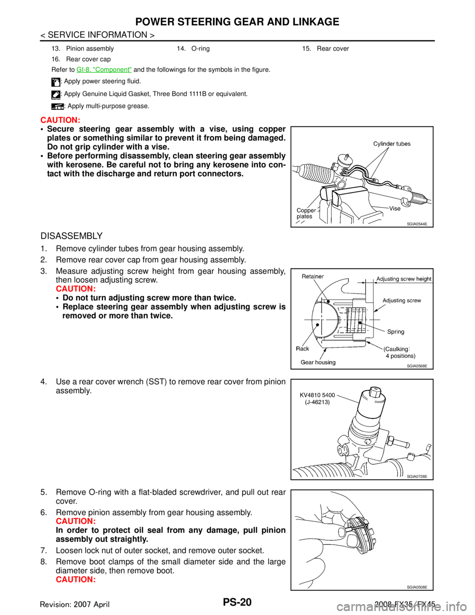
CAUTION:
Secure steering gear assembly with a vise, using copperplates or something similar to prevent it from being damaged.
Do not grip cylinder with a vise.
Before performing disassembly, clean steering gear assembly
with kerosene. Be careful not to bring any kerosene into con-
tact with the discharge an d return port connectors.
DISASSEMBLY
1. Remove cylinder tubes from gear housing assembly.
2. Remove rear cover cap from gear housing assembly.
3. Measure adjusting screw height from gear housing assembly,
then loosen adjusting screw.
CAUTION:
Do not turn adjusting screw more than twice.
Replace steering gear assembly when adjusting screw is
removed or more than twice.
4. Use a rear cover wrench (SST) to remove rear cover from pinion assembly.
5. Remove O-ring with a flat-bladed screwdriver, and pull out rear cover.
6. Remove pinion assembly from gear housing assembly. CAUTION:
In order to protect oil seal from any damage, pull pinion
assembly out straightly.
7. Loosen lock nut of outer socket, and remove outer socket.
8. Remove boot clamps of the small diameter side and the large diameter side, then remove boot.
CAUTION:
13. Pinion assembly 14. O-ring 15. Rear cover
16. Rear cover cap
Refer to GI-8, "
Component" and the followings for the symbols in the figure.
: Apply power steering fluid.
: A p p l y G e n u i n e L i q u i d G a s k e t , T h r e e B o n d 1111 B o r e q u i v a l e n t .
: Apply multi-purpose grease.
SGIA0544E
SGIA0568E
SGIA0728E
SGIA0508E
3AA93ABC3ACD3AC03ACA3AC03AC63AC53A913A773A893A873A873A8E3A773A983AC73AC93AC03AC3
3A893A873A873A8F3A773A9D3AAF3A8A3A8C3A863A9D3AAF3A8B3A8C
Page 3479 of 3924
![INFINITI FX35 2008 Service Manual
PS-24
< SERVICE INFORMATION >
POWER STEERING GEAR AND LINKAGE
c. When installing outer rack oil seal, cover the end of rack with anOHP sheet [70 mm (2.76 in) × 100 mm (3.94 in)]. It will avoid
dama INFINITI FX35 2008 Service Manual
PS-24
< SERVICE INFORMATION >
POWER STEERING GEAR AND LINKAGE
c. When installing outer rack oil seal, cover the end of rack with anOHP sheet [70 mm (2.76 in) × 100 mm (3.94 in)]. It will avoid
dama](/manual-img/42/57017/w960_57017-3478.png)
PS-24
< SERVICE INFORMATION >
POWER STEERING GEAR AND LINKAGE
c. When installing outer rack oil seal, cover the end of rack with anOHP sheet [70 mm (2.76 in) × 100 mm (3.94 in)]. It will avoid
damaging rack oil seal. Then place oil seal on sheet. Pull rack oil
seal along with OHP sheet until they pass rack end. Then
remove OHP sheet.
d. Install end cover assembly to rack, move it to gear housing assembly.
5. Using a 45 mm (1.77 in) open head (suitable tool), tighten end cover assembly at the specified torque.
CAUTION:
Do not damage rack surface. If it is damaged, it may cause
oil leaks. Replace rack assembly.
6. After tightening end cover assembly, caulk cylinder at one point as shown in the figure using a punch. This will prevent end cover
from getting loose.
7. Install pinion assembly to gear housing assembly. CAUTION:
In order to protect oil seal from any damage, insert pinion
assembly out straightly.
8. Apply recommended fluid to O-ring. Install O-ring to rear cover.
9. Use a rear cover wrench (SST), install rear cover to gear hous- ing assembly.
10. Confirm projection on rear cover cap nearly fit with marking posi- tion on gear housing assembly.
11. Apply recommended thread locking sealant to the thread (2 turns thread), and then screw in the adjusting screw until it
reaches height “H” from gear housing assembly measured
before disassembling.
12. Rotate pinion ten times whole range of rack so that parts get to fit with each other.
SGIA0157E
SST081B
SGIA0158E
SGIA0568E
3AA93ABC3ACD3AC03ACA3AC03AC63AC53A913A773A893A873A873A8E3A773A983AC73AC93AC03AC3
3A893A873A873A8F3A773A9D3AAF3A8A3A8C3A863A9D3AAF3A8B3A8C
Page 3548 of 3924
RFD-6
< SERVICE INFORMATION >
PREPARATION
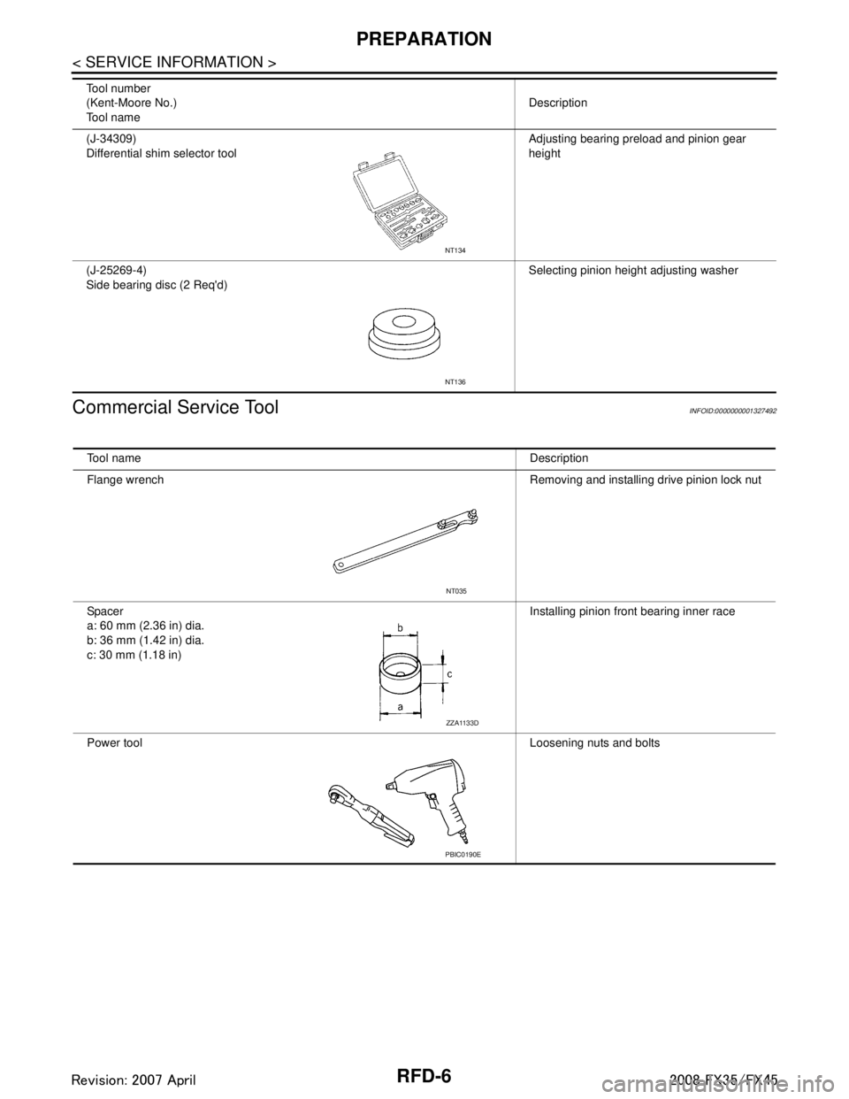
Commercial Service Tool
INFOID:0000000001327492
(J-34309)
Differential shim selector tool Adjusting bearing preload and pinion gear
height
(J-25269-4)
Side bearing disc (2 Req'd) Selecting pinion height adjusting washer
Tool number
(Kent-Moore No.)
Tool name
Description
NT134
NT136
Tool name
Description
Flange wrench Removing and installing drive pinion lock nut
Spacer
a: 60 mm (2.36 in) dia.
b: 36 mm (1.42 in) dia.
c: 30 mm (1.18 in) Installing pinion front bearing inner race
Power tool Loosening nuts and bolts
NT035
ZZA1133D
PBIC0190E
3AA93ABC3ACD3AC03ACA3AC03AC63AC53A913A773A893A873A873A8E3A773A983AC73AC93AC03AC3
3A893A873A873A8F3A773A9D3AAF3A8A3A8C3A863A9D3AAF3A8B3A8C
Page 3560 of 3924
RFD-18
< SERVICE INFORMATION >
REAR FINAL DRIVE ASSEMBLY
ASSEMBLY INSPECTION AND ADJUSTMENT
Before inspection and adjustment, drain gear oil.
Total Preload Torque
1. Secure final drive assembly onto an attachment.
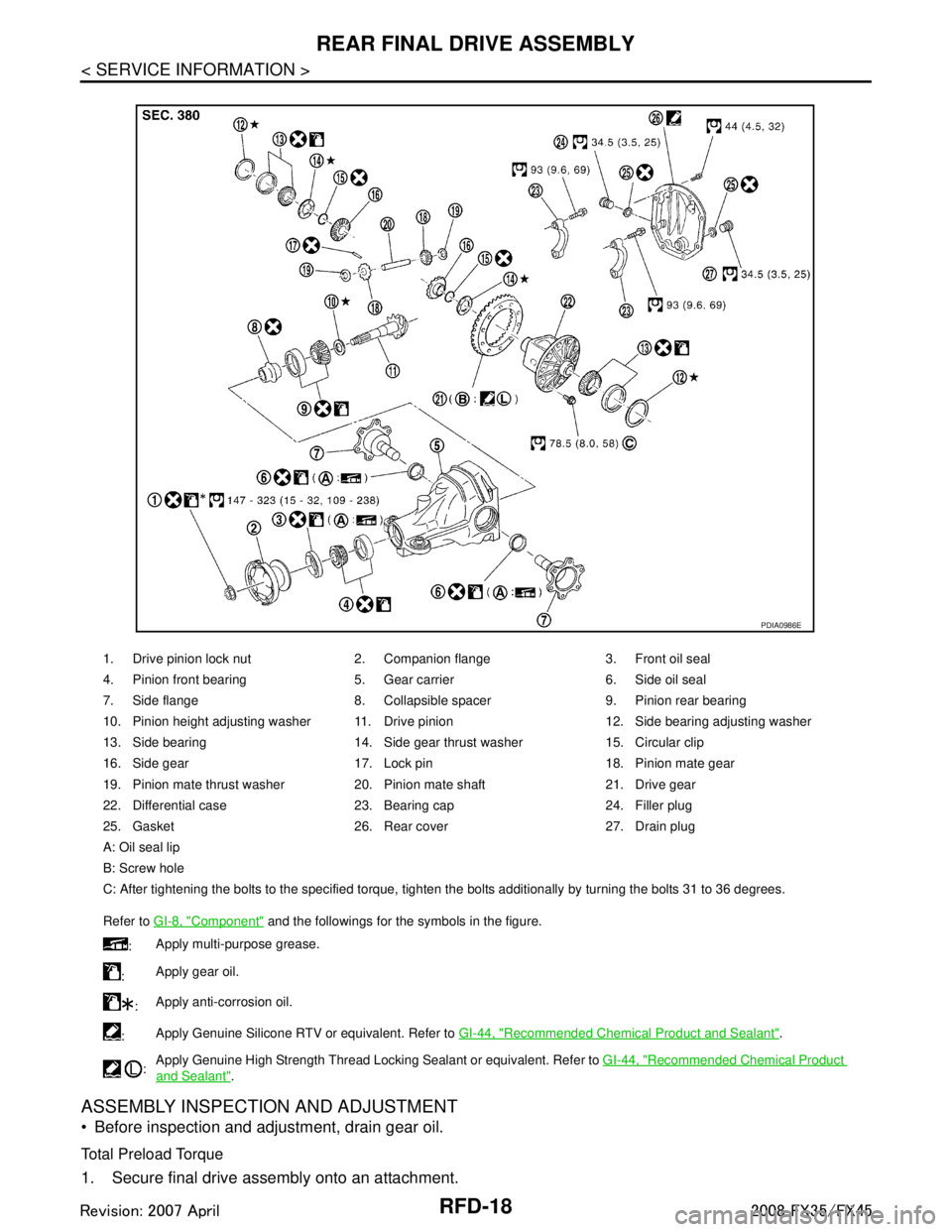
1. Drive pinion lock nut 2. Companion flange 3. Front oil seal
4. Pinion front bearing 5. Gear carrier 6. Side oil seal
7. Side flange 8. Collapsible spacer 9. Pinion rear bearing
10. Pinion height adjusting washer 11. Drive pinion 12. Side bearing adjusting washer
13. Side bearing 14. Side gear thrust washer 15. Circular clip
16. Side gear 17. Lock pin 18. Pinion mate gear
19. Pinion mate thrust washer 20. Pinion mate shaft 21. Drive gear
22. Differential case 23. Bearing cap 24. Filler plug
25. Gasket 26. Rear cover 27. Drain plug
A: Oil seal lip
B: Screw hole
C: After tightening the bolts to the specified torque, tighten the bolts additionally by turning the bolts 31 to 36 degrees.
Refer to GI-8, "
Component" and the followings for the symbols in the figure.
: Apply multi-purpose grease.
: Apply gear oil.
: Apply anti-corrosion oil.
: Apply Genuine Silicone RTV or equivalent. Refer to
GI-44, "
Recommended Chemical Product and Sealant".
: Apply Genuine High Strength Thread Locking Sealant or equivalent. Refer to
GI-44, "
Recommended Chemical Product
and Sealant".
PDIA0986E
3AA93ABC3ACD3AC03ACA3AC03AC63AC53A913A773A893A873A873A8E3A773A983AC73AC93AC03AC3
3A893A873A873A8F3A773A9D3AAF3A8A3A8C3A863A9D3AAF3A8B3A8C
Page 3563 of 3924
REAR FINAL DRIVE ASSEMBLYRFD-21
< SERVICE INFORMATION >
CEF
G H
I
J
K L
M A
B
RFD
N
O P
4. If tooth contact is improperly adjusted, follow the procedure
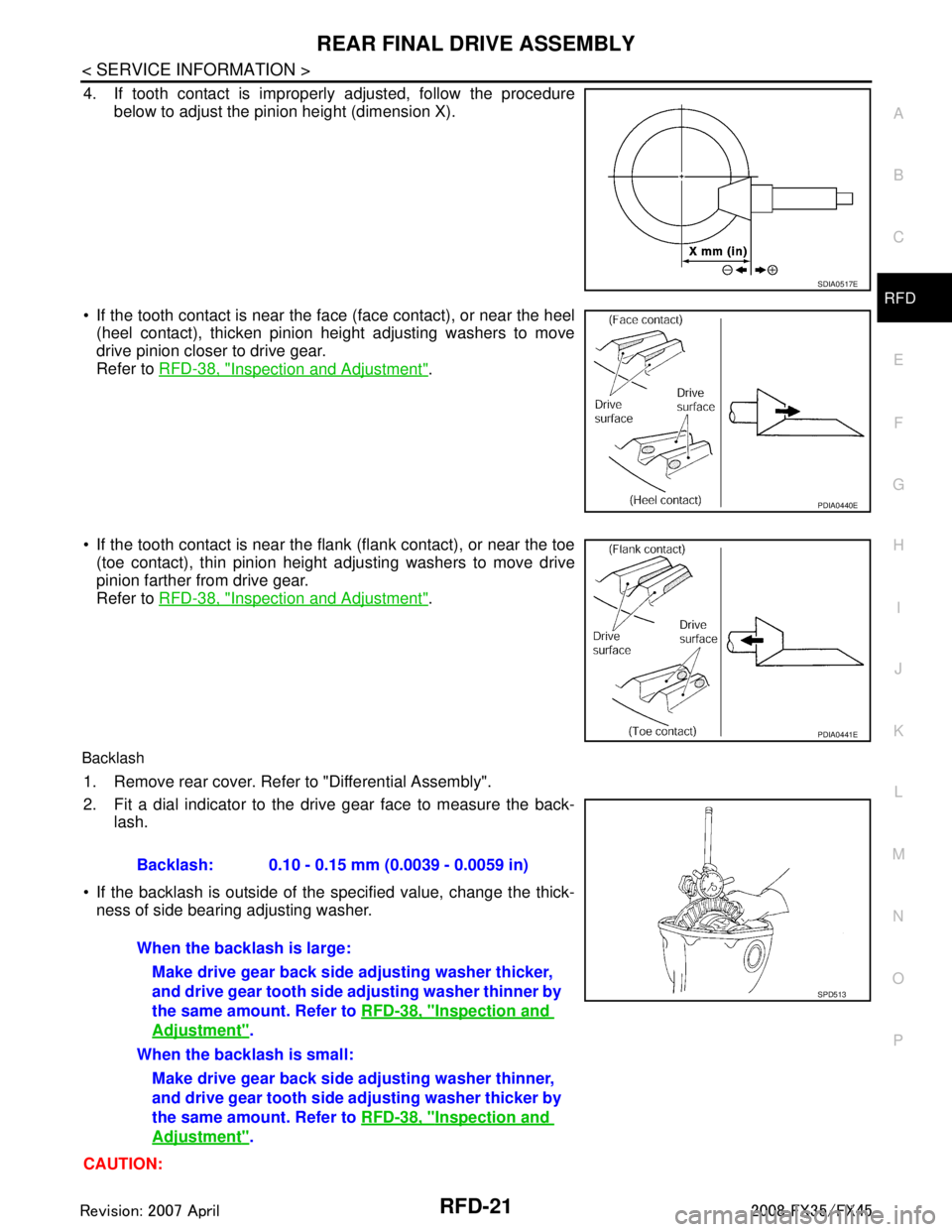
below to adjust the pinion height (dimension X).
If the tooth contact is near the face (face contact), or near the heel (heel contact), thicken pinion height adjusting washers to move
drive pinion closer to drive gear.
Refer to RFD-38, "
Inspection and Adjustment".
If the tooth contact is near the flank (flank contact), or near the toe
(toe contact), thin pinion height adjusting washers to move drive
pinion farther from drive gear.
Refer to RFD-38, "
Inspection and Adjustment".
Backlash
1. Remove rear cover. Refer to "Differential Assembly".
2. Fit a dial indicator to the drive gear face to measure the back-
lash.
If the backlash is outside of the specified value, change the thick- ness of side bearing adjusting washer.
CAUTION:
SDIA0517E
PDIA0440E
PDIA0441E
Backlash: 0.10 - 0.15 mm (0.0039 - 0.0059 in)
When the backlash is large: Make drive gear back side adjusting washer thicker,
and drive gear tooth side adjusting washer thinner by
the same amount. Refer to RFD-38, "
Inspection and
Adjustment".
When the backlash is small: Make drive gear back side adjusting washer thinner,
and drive gear tooth side ad justing washer thicker by
the same amount. Refer to RFD-38, "
Inspection and
Adjustment".
SPD513
3AA93ABC3ACD3AC03ACA3AC03AC63AC53A913A773A893A873A873A8E3A773A983AC73AC93AC03AC3
3A893A873A873A8F3A773A9D3AAF3A8A3A8C3A863A9D3AAF3A8B3A8C
Page 3568 of 3924
RFD-26
< SERVICE INFORMATION >
REAR FINAL DRIVE ASSEMBLY
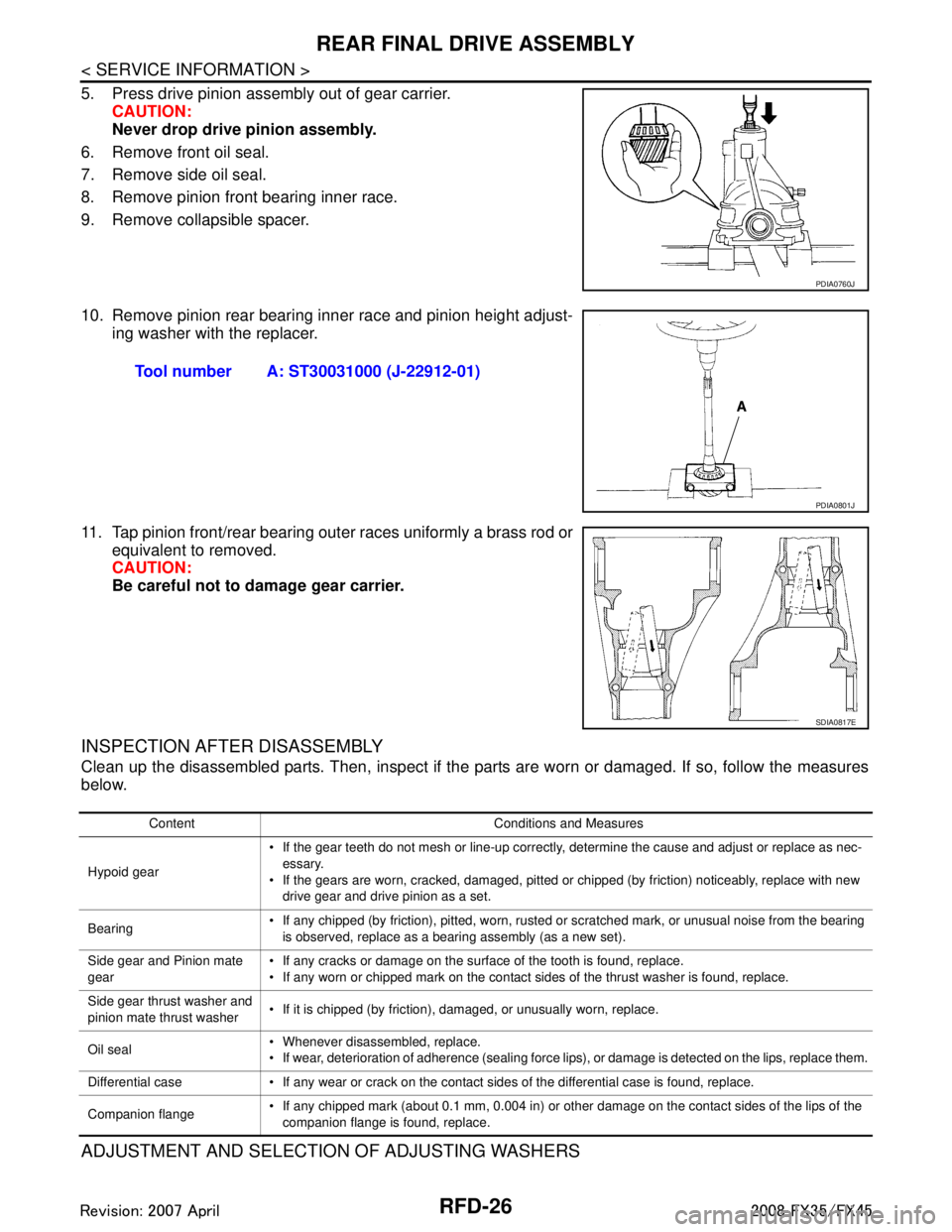
5. Press drive pinion assembly out of gear carrier.CAUTION:
Never drop drive pinion assembly.
6. Remove front oil seal.
7. Remove side oil seal.
8. Remove pinion front bearing inner race.
9. Remove collapsible spacer.
10. Remove pinion rear bearing inner race and pinion height adjust- ing washer with the replacer.
11. Tap pinion front/rear bearing outer races uniformly a brass rod or equivalent to removed.
CAUTION:
Be careful not to damage gear carrier.
INSPECTION AFTER DISASSEMBLY
Clean up the disassembled parts. Then, inspect if the parts are worn or damaged. If so, follow the measures
below.
ADJUSTMENT AND SELECTION OF ADJUSTING WASHERS
PDIA0760J
Tool number A: ST30031000 (J-22912-01)
PDIA0801J
SDIA0817E
Content Conditions and Measures
Hypoid gear If the gear teeth do not mesh or line-up correctly, determine the cause and adjust or replace as nec-
essary.
If the gears are worn, cracked, damaged, pitted or chipped (by friction) noticeably, replace with new drive gear and drive pinion as a set.
Bearing If any chipped (by friction), pitted, worn, rusted or scratched mark, or unusual noise from the bearing
is observed, replace as a bearing assembly (as a new set).
Side gear and Pinion mate
gear If any cracks or damage on the surface of the tooth is found, replace.
If any worn or chipped mark on the contact sides of the thrust washer is found, replace.
Side gear thrust washer and
pinion mate thrust washer If it is chipped (by friction), damaged, or unusually worn, replace.
Oil seal Whenever disassembled, replace.
If wear, deterioration of adherence (sealing force lips), or damage is detected on the lips, replace them.
Differential case If any wear or crack on the contact sides of the differential case is found, replace.
Companion flange If any chipped mark (about 0.1 mm, 0.004 in) or other damage on the contact sides of the lips of the
companion flange is found, replace.
3AA93ABC3ACD3AC03ACA3AC03AC63AC53A913A773A893A873A873A8E3A773A983AC73AC93AC03AC3
3A893A873A873A8F3A773A9D3AAF3A8A3A8C3A863A9D3AAF3A8B3A8C
Page 3570 of 3924
RFD-28
< SERVICE INFORMATION >
REAR FINAL DRIVE ASSEMBLY
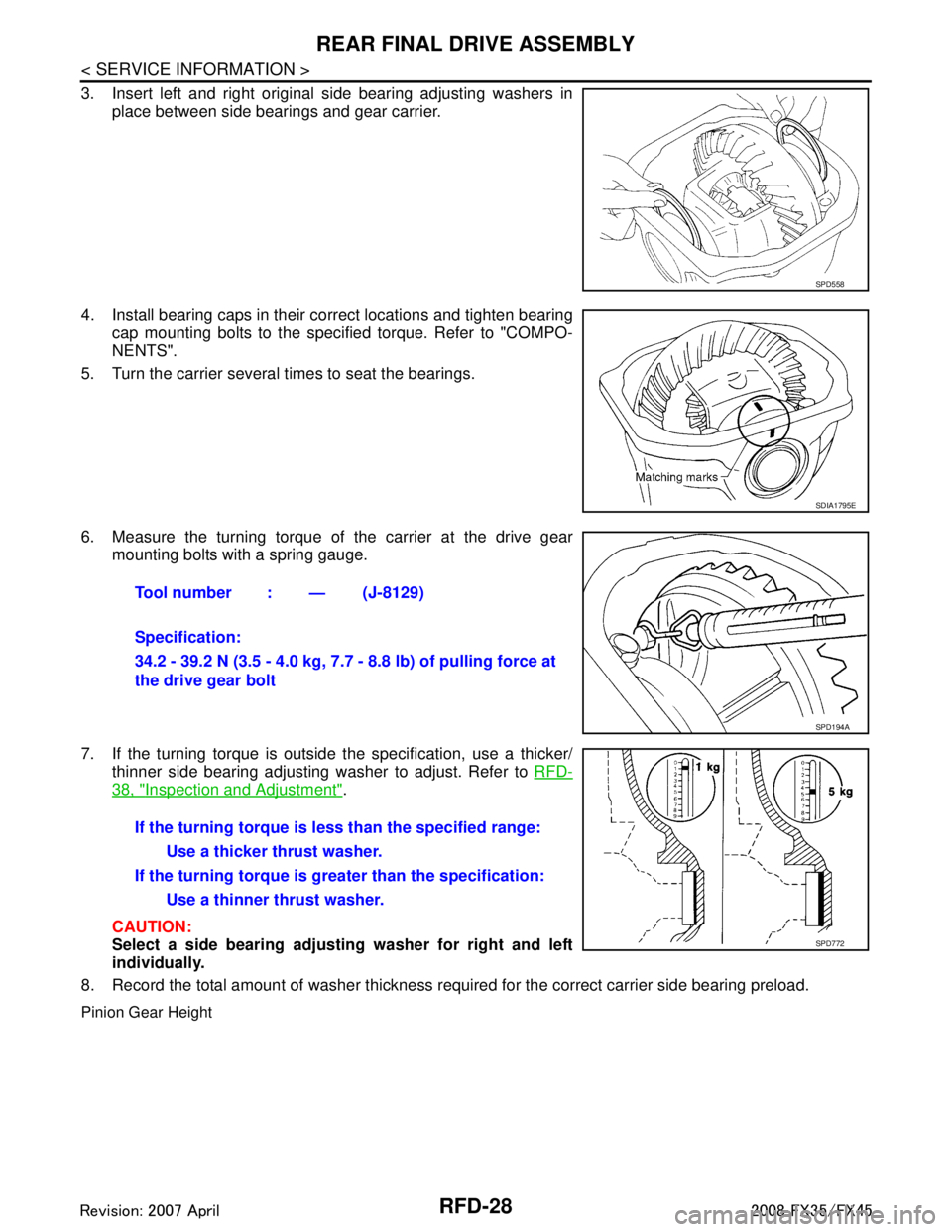
3. Insert left and right original side bearing adjusting washers inplace between side bearings and gear carrier.
4. Install bearing caps in their correct locations and tighten bearing cap mounting bolts to the specified torque. Refer to "COMPO-
NENTS".
5. Turn the carrier several times to seat the bearings.
6. Measure the turning torque of the carrier at the drive gear mounting bolts with a spring gauge.
7. If the turning torque is outside the specification, use a thicker/ thinner side bearing adjusting washer to adjust. Refer to RFD-
38, "Inspection and Adjustment".
CAUTION:
Select a side bearing adjust ing washer for right and left
individually.
8. Record the total amount of washer thickness required for the correct carrier side bearing preload.
Pinion Gear Height
SPD558
SDIA1795E
Tool number : — (J-8129)
Specification:
34.2 - 39.2 N (3.5 - 4.0 kg, 7.7 - 8.8 lb) of pulling force at
the drive gear bolt
SPD194A
If the turning torque is l ess than the specified range:
Use a thicker thrust washer.
If the turning torque is gr eater than the specification:
Use a thinner thrust washer.
SPD772
3AA93ABC3ACD3AC03ACA3AC03AC63AC53A913A773A893A873A873A8E3A773A983AC73AC93AC03AC3
3A893A873A873A8F3A773A9D3AAF3A8A3A8C3A863A9D3AAF3A8B3A8C
Page 3571 of 3924
REAR FINAL DRIVE ASSEMBLYRFD-29
< SERVICE INFORMATION >
CEF
G H
I
J
K L
M A
B
RFD
N
O P
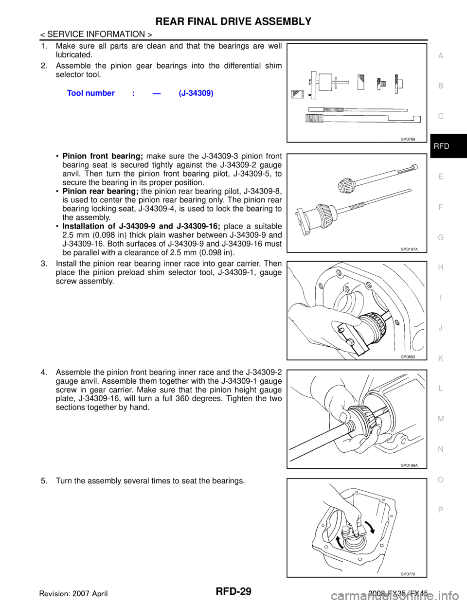
1. Make sure all parts are clean and that the bearings are well lubricated.
2. Assemble the pinion gear beari ngs into the differential shim
selector tool.
Pinion front bearing; make sure the J-34309-3 pinion front
bearing seat is secured tightly against the J-34309-2 gauge
anvil. Then turn the pinion front bearing pilot, J-34309-5, to
secure the bearing in its proper position.
Pinion rear bearing; the pinion rear bearing pilot, J-34309-8,
is used to center the pinion rear bearing only. The pinion rear
bearing locking seat, J-34309-4, is used to lock the bearing to
the assembly.
Installation of J-34309-9 and J-34309-16; place a suitable
2.5 mm (0.098 in) thick plain washer between J-34309-9 and
J-34309-16. Both surfaces of J-34309-9 and J-34309-16 must
be parallel with a clearance of 2.5 mm (0.098 in).
3. Install the pinion rear bearing inner race into gear carrier. Then place the pinion preload shim selector tool, J-34309-1, gauge
screw assembly.
4. Assemble the pinion front bearing inner race and the J-34309-2 gauge anvil. Assemble them together with the J-34309-1 gauge
screw in gear carrier. Make sure that the pinion height gauge
plate, J-34309-16, will turn a full 360 degrees. Tighten the two
sections together by hand.
5. Turn the assembly several times to seat the bearings. Tool number : — (J-34309)
SPD769
SPD197A
SPD893
SPD199A
SPD770
3AA93ABC3ACD3AC03ACA3AC03AC63AC53A913A773A893A873A873A8E3A773A983AC73AC93AC03AC3
3A893A873A873A8F3A773A9D3AAF3A8A3A8C3A863A9D3AAF3A8B3A8C