Page 193 of 266

12
A
190
VI
The puncture repair kit is a complete system including a compressor and a setting product.
It allows you to temporarily repair the tyre, to enable you to drive to your nearest garage.
Depending on model, it is located either in the boot well or in the compartment under the left hand second-row passenger (open the fl a p b y t u r n i n g t h e s c r e w a q u a r t e r turn).
Using the puncture repair kit
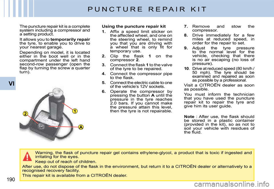
1. A f fi x a s p e e d l i m i t s t i c k e r o n the affected wheel, and one on the steering wheel, to remind you that you are driving with a w h e e l t h a t i s o n l y fi t f o r temporary use.
2. C l i p t h e fl a s k 1 on the compressor 2.
3. C o n n e c t t h e fl a s k 1 to the valve of the tyre to be repaired.
4. Connect the compressor pipe t o t h e fl a s k .
5.Connect the electric cable to one of the vehicle’s 12V sockets.
6. Operate the compressor by pressing the button A until the pressure in the tyre reaches 2.0 bars. If you cannot make the pressure attain this level, then the tyre is not repairable.
7. Remove and stow the compressor.
8. Drive immediately for a few miles at reduced speed, in order for the repair to set.
9. Adjust the tyre pressure to the normal level for the vehicle, checking that there is no air escaping (no loss of pressure).
10. Drive at reduced speed (80 km/h / 50 mph). The tyre should be examined and repaired as soon as possible by a professional.
Visit a CITROËN dealer as soon as possible.
You must inform the technician that you have used the puncture repair kit to repair the tyre and give him its user guide.
W a r n i n g , t h e fl a s k o f p u n c t u r e r e p a i r g e l c o n t a i n s e t h y l e n e - g l y c o l , a p r o d u c t t h a t i s t o x i c i f i n g e s t e d a n d irritating for the eyes.
Keep out of reach of children.
A f t e r u s e , d o n o t d i s p o s e o f t h e fl a s k i n t h e e n v i r o n m e n t , b u t r e t u r n i t t o a C I T R O Ë N d e a l e r o r a l t e r n a t i v e l y t o a recognised recovery facility.
This repair kit is available from a CITROËN dealer.
P U N C T U R E R E P A I R K I T
Note : A f t e r u s e , t h e fl a s k s h o u l d be stored in a plastic container (provided in the kit), so as not to soil your vehicle with residues of t h e fl u i d .
Page 194 of 266

23
4
567
89
1
VI
191
C H A N G I N G A W H E E L
TOOLS
The tools are to be found either in the compartment under the second-row passenger footwells or in the well under the third-row seats (de-pending on equipment).
S w i t c h o n y o u r h a z a r d w a r n i n g l i g h t s , e n s u r e t h a t a n y p a s s e n g e r s l e a v e t h e v e h i c l e a n d fi n d a s a f e p l a c e t o w a i t a w a y f r o m t r a f fi c ( e . g . b e h i n d c r a s h b a r r i e r s o r o n a g r a s s v e r g e ) .
Never get underneath the vehicle if it is supported only by the jack ; use a stand.
It is essential not to exceed a speed of 80 km/h (50 mph) on your spare wheel.
H a v e t h e o r i g i n a l w h e e l r e p a i r e d a n d r e fi t t e d a s s o o n a s p o s s i b l e .
5- Vehicle jack with handle
6- Removable towing eye
7- Two chocks, provided for chan ging a wheel or for other uses on the vehicle (such as unlocking the electric parking brake)
8- Electric parking brake unlocking 8-device
9- Anti-theft socket.
1- Tool for removing the central trim on alloy wheels
2- Tool for removing the chrome covers on the wheel bolts on alloy wheels
3- Centring guide
4- Tool for removing the wheel bolts
Page 195 of 266

192
VI
C H A N G I N G A W H E E L
ACCESSING THE SPARE WHEEL
1. Move the third-row seat, right-hand side (7 seater model).
2. Retrieve the extension that is attached to the rear of the seat well.
3. Engage the extension on the pinion located under the carpet in the seat well.
4. Using the wheel brace on the extension to turn the pinion clockwise, release the cable to lower the spare wheel to the ground.
5. Remove the wheel from under the vehicle, disengaging the linking plate in the centre of the wheel.
STOWING THE AFFECTED WHEEL
1. It is essential to direct the valve upwards.
2. Pass the linking plate through the centre of the w h e e l ( fi r s t r e m o v i n g t h e c e n t r a l t r i m o n c e r t a i n alloy wheels).
3. Turn the pinion anti-clockwise to draw in the cable. First the pinion will turn idly, then the cable will tighten to raise the wheel. Check that the wheel i s t i g h t a g a i n s t t h e v e h i c l e fl o o r a n d n o t i n t e r f e r i n g with other nearby components (e.g. the exhaust).
4. Stow the tools and chocks.
W i t h t h e a f f e c t e d r o a d w h e e l n o w u n d e r t h e v e h i c l e fl o o r , t h e v e h i c l e h a s r e d u c e d g r o u n d c l e a r a n c e , so take extra care when reversing or driving on uneven surfaces, inclu ding kerbs.
Retrieval of the spare wheel and stowage of the affected road wheel are operations that should be done with the vehicle supported on its wheels, not by the jack.
Note : The pinion to release the spare wheel is located under the boot carpet, on the right hand side in the wheel well for the Grand C4 Picasso and on the left hand side for the C4 Picasso.
Grand C4 PicassoC4 Picasso
Page 196 of 266

A
1
VI
193
C H A N G I N G A W H E E L
REMOVING A WHEEL
1. Park the vehicle on level, stable and non-slippery ground. Apply the parking brake.
Switch off the ignition, check that the parking brake is applied (message and warning lamp in the instrument panel) a n d e n g a g e fi r s t g e a r o r reverse gear depending on the slope (P if an automatic gearbox, D or R if a 6-speed electronic gearbox).
2. Use a chock to secure the vehicle more safely. Place the chock in front of the wheel that is opposite the wheel affected.
3. Detach the trim using the removing tool 4, pulling in the area of the valve.
For vehicles with alloy wheels, insert the trim removing tool 1into the recess in the central trim and lever it off.
For vehicles with alloy wheels that have visible bolts, remove the chromes covers using the tool 2.
Before any operation of this sort, it is advisable to deactivate your pneumatic suspension (see “Pneumatic sus-pension”). When changing a wheel, it is essential to immobil ise the vehicle on ground that is level, stable and non-slippery.
4. Slacken the wheel bolts. For vehicles with alloy wheels, undo the anti-theft bolts using tool 9.
5. Position the jack under the vehicle (see diagrams), at the jacking point A closest to the wheel to be changed.
6. Unwind the jack 5 until its bracket is in contact with the ground. Make sure that the jack is vertical under the jacking point used.
7. Continue to extend the jack so as to raise the vehicle.
8. Undo the wheel bolts and remove the wheel.
Page 197 of 266