2007 TOYOTA SIENNA flat tire
[x] Cancel search: flat tirePage 2337 of 3000
TIRE AND WHEEL – TIRE PRESSURE WARNING VALVE AND TRANSMITTERTW–85
TW
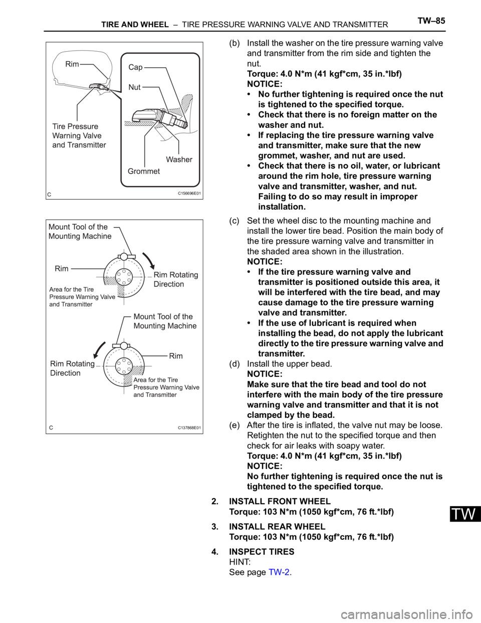
(b) Install the washer on the tire pressure warning valve
and transmitter from the rim side and tighten the
nut.
Torque: 4.0 N*m (41 kgf*cm, 35 in.*lbf)
NOTICE:
• No further tightening is required once the nut
is tightened to the specified torque.
• Check that there is no foreign matter on the
washer and nut.
• If replacing the tire pressure warning valve
and transmitter, make sure that the new
grommet, washer, and nut are used.
• Check that there is no oil, water, or lubricant
around the rim hole, tire pressure warning
valve and transmitter, washer, and nut.
Failing to do so may result in improper
installation.
(c) Set the wheel disc to the mounting machine and
install the lower tire bead. Position the main body of
the tire pressure warning valve and transmitter in
the shaded area shown in the illustration.
NOTICE:
• If the tire pressure warning valve and
transmitter is positioned outside this area, it
will be interfered with the tire bead, and may
cause damage to the tire pressure warning
valve and transmitter.
• If the use of lubricant is required when
installing the bead, do not apply the lubricant
directly to the tire pressure warning valve and
transmitter.
(d) Install the upper bead.
NOTICE:
Make sure that the tire bead and tool do not
interfere with the main body of the tire pressure
warning valve and transmitter and that it is not
clamped by the bead.
(e) After the tire is inflated, the valve nut may be loose.
Retighten the nut to the specified torque and then
check for air leaks with soapy water.
Torque: 4.0 N*m (41 kgf*cm, 35 in.*lbf)
NOTICE:
No further tightening is required once the nut is
tightened to the specified torque.
2. INSTALL FRONT WHEEL
Torque: 103 N*m (1050 kgf*cm, 76 ft.*lbf)
3. INSTALL REAR WHEEL
Torque: 103 N*m (1050 kgf*cm, 76 ft.*lbf)
4. INSPECT TIRES
HINT:
See page TW-2.
C156696E01
C137868E01
Page 2345 of 3000
TIRE AND WHEEL – TIRE PRESSURE WARNING ECUTW–89
TW
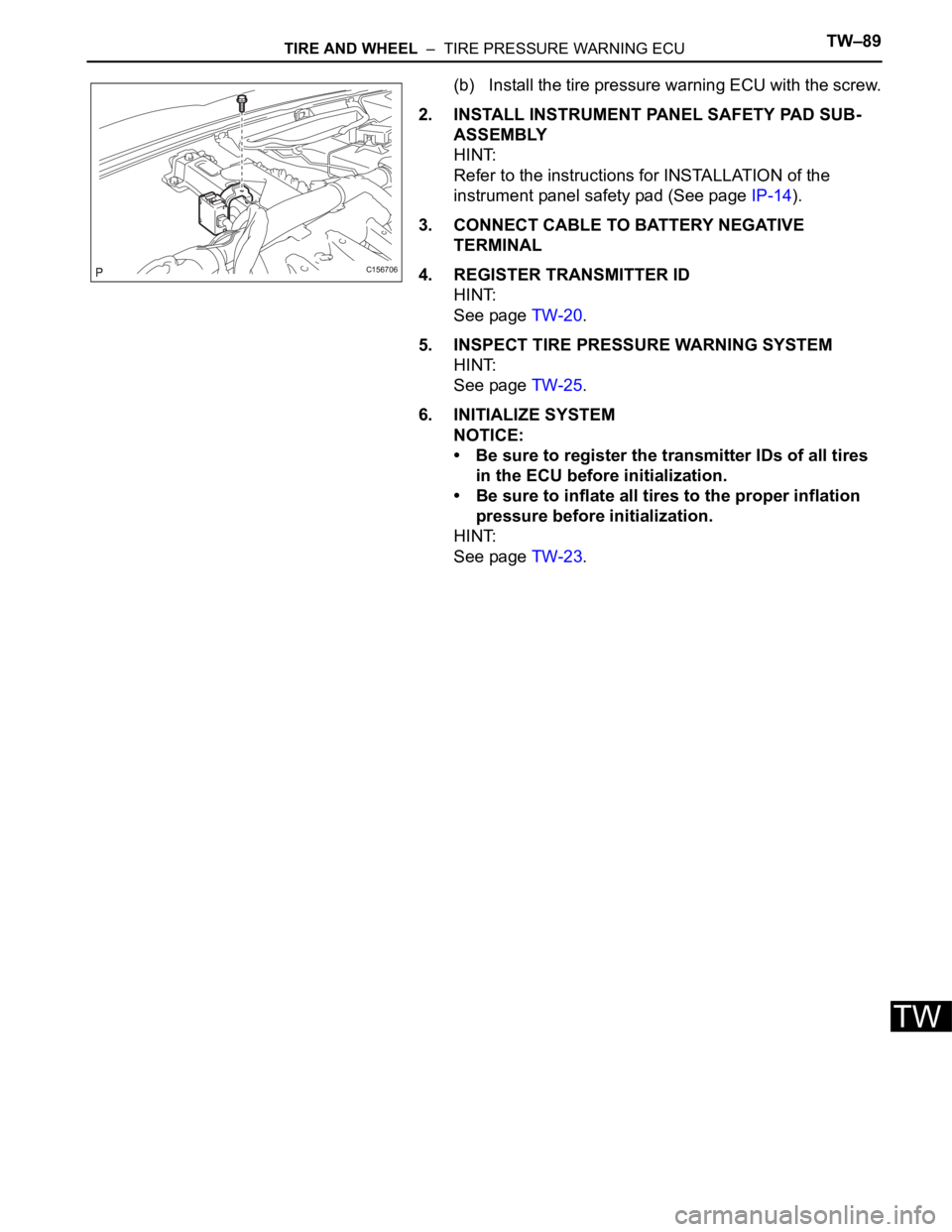
(b) Install the tire pressure warning ECU with the screw.
2. INSTALL INSTRUMENT PANEL SAFETY PAD SUB-
ASSEMBLY
HINT:
Refer to the instructions for INSTALLATION of the
instrument panel safety pad (See page IP-14).
3. CONNECT CABLE TO BATTERY NEGATIVE
TERMINAL
4. REGISTER TRANSMITTER ID
HINT:
See page TW-20.
5. INSPECT TIRE PRESSURE WARNING SYSTEM
HINT:
See page TW-25.
6. INITIALIZE SYSTEM
NOTICE:
• Be sure to register the transmitter IDs of all tires
in the ECU before initialization.
• Be sure to inflate all tires to the proper inflation
pressure before initialization.
HINT:
See page TW-23.
C156706
Page 2346 of 3000

TIRE AND WHEEL – TIRE PRESSURE WARNING SYSTEMTW–31
TW
PROBLEM SYMPTOMS TABLE
HINT:
• Use the table below to help determine the cause of the
problem symptom. The potential causes of the symptoms
are listed in order of probability in the "Suspected Area"
column of the table. Check each symptom by checking the
suspected areas in the order they are listed. Replace parts
as necessary.
• Inspect the fuses and relays related to this system before
inspecting the suspected areas below.
TIRE PRESSURE WARNING SYSTEM:
Symptom Suspected Area See page
Tire pressure warning light does not illuminate, despite
tire pressure decreasingInitializationTW-23
Check DATA LIST (Tire inflation pressure)TW-35
ID code check (Registration)TW-20
Tire pressure warning light illuminated (Goes off during
initial check)ECU power source circuitTW-77
Tire pressure warning light circuitTW-74
Tire pressure warning light illuminated (Comes on
during initial check)Check DATA LIST (Tire inflation pressure)TW-35
Tire pressure warning light circuitTW-74
ID code check (Registration)TW-20
Initialization cannot be done Tire pressure reset switch circuitTW-72
DTC check cannot be doneECU power source circuitTW-77
TC and CG terminal circuitTW-79
Page 2356 of 3000

TW–38TIRE AND WHEEL – TIRE PRESSURE WARNING SYSTEM
TW
DATA LIST / ACTIVE TEST
1. DATA LIST
HINT:
Using the intelligent tester to read the DATA LIST allows
the values or states of switches, sensor, actuators and
other items to be read without removing any parts. This
non-intrusive inspection can be very useful because
intermittent conditions or signals may be discovered
before parts or wiring is disturbed. Reading the DATA
LIST information early in troubleshooting is one way to
save diagnostic time.
NOTICE:
In the table below, the values listed under "Normal
Condition" are reference values. Do not depend
solely on these reference values when deciding
whether a part is faulty or not.
(a) Make sure that the ignition switch is off.
(b) Connect the intelligent tester to DLC3.
(c) Turn the ignition switch to the ON position.
(d) Following the display on the intelligent tester, read
"DATA LIST".
Tester Display Measurement Item/Range Normal Condition Diagnostic Note
MODE STATUSTire pressure warning system mode/NORMAL
or REG 2nd or REG M or TESTNORMAL: Normal mode
TEST: Test mode-
MAIN TIRENumber of main tire ID to be registered/0, 1, 2,
3, 40 to 4 should be displayed -
VEHICLE SPDVehicle speed reading/min.: 0 km/h (0 mph),
max.: 255 km/h (158 mph)Actual vehicle speedSpeed indicated on the
combination meter
REGIT ID1 CODE
Registered ID1 code/min.: 0, max.: FFFFFFF
*1The ID No. registered in the
transmitter ID1 is displayed-
REGIT ID2 CODE
Registered ID2 code/min.: 0, max.: FFFFFFF
*1The ID No. registered in the
transmitter ID2 is displayed-
REGIT ID3 CODE
Registered ID3 code/min.: 0, max.: FFFFFFF
*1The ID No. registered in the
transmitter ID3 is displayed-
REGIT ID4 CODE
Registered ID4 code/min.: 0, max.: FFFFFFF
*1The ID No. registered in the
transmitter ID4 is displayed-
TRANS STATUS ID code transmission status/FINISH or NOW FINISH or NOW -
INITIAL SW Tire pressure warning reset switch/ON, OFFON: Switch on
OFF: Switch off-
TIREPRESS1ID1 tire inflation pressure (Absolute pressure) /
min.: 100 kPa (1 kgf/cm
2, 14 psi)
max.: 449.35 kPa (4.5 kgf/cm2, 63 psi)Actual tire inflation pressureIf 100 kPa (1 kgf/cm
2, 14 psi)
for absolute pressure is
displayed, the data has not
been received.
*2
TIREPRESS2ID2 tire inflation pressure (Absolute pressure) /
min.: 100 kPa (1 kgf/cm2, 14 psi)
max.: 449.35 kPa (4.5 kgf/cm2, 63 psi)Actual tire inflation pressureIf 100 kPa (1 kgf/cm
2, 14 psi)
for absolute pressure is
displayed, the data has not
been received.
*2
TIREPRESS3ID3 tire inflation pressure (Absolute pressure) /
min.: 100 kPa (1 kgf/cm2, 14 psi)
max.: 449.35 kPa (4.5 kgf/cm2, 63 psi)Actual tire inflation pressureIf 100 kPa (1 kgf/cm
2, 14 psi)
for absolute pressure is
displayed, the data has not
been received.
*2
TIREPRESS4ID4 tire inflation pressure (Absolute pressure) /
min.: 100 kPa (1 kgf/cm2, 14 psi)
max.: 449.35 kPa (4.5 kgf/cm2, 63 psi)Actual tire inflation pressureIf 100 kPa (1 kgf/cm
2, 14 psi)
for absolute pressure is
displayed, the data has not
been received.
*2
Page 2678 of 3000
SR–2STEERING COLUMN – STEERING SYSTEM
SR
PROBLEM SYMPTOMS TABLE
HINT:
Use the table below to help determine the cause of the
problem. Likely causes of the problem are indicated in
descending order. Check each suspected area in order.
Repair or replace the faulty parts or perform adjustments as
necessary.
STEERING SYSTEM
ON-VEHICLE INSPECTION
1. CHECK STEERING WHEEL FREEPLAY
(a) Stop the vehicle and face the tires straight ahead.
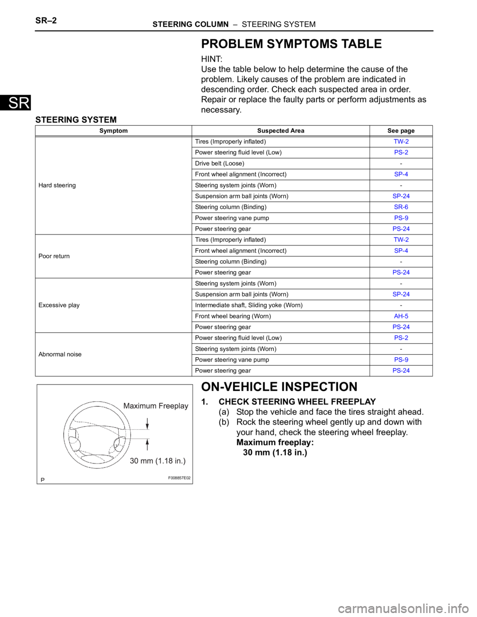
(b) Rock the steering wheel gently up and down with
your hand, check the steering wheel freeplay.
Maximum freeplay:
30 mm (1.18 in.)
Symptom Suspected Area See page
Hard steeringTires (Improperly inflated)TW-2
Power steering fluid level (Low)PS-2
Drive belt (Loose) -
Front wheel alignment (Incorrect)SP-4
Steering system joints (Worn) -
Suspension arm ball joints (Worn)SP-24
Steering column (Binding)SR-6
Power steering vane pumpPS-9
Power steering gearPS-24
Poor returnTires (Improperly inflated)TW-2
Front wheel alignment (Incorrect)SP-4
Steering column (Binding) -
Power steering gearPS-24
Excessive playSteering system joints (Worn) -
Suspension arm ball joints (Worn)SP-24
Intermediate shaft, Sliding yoke (Worn) -
Front wheel bearing (Worn)AH-5
Power steering gearPS-24
Abnormal noisePower steering fluid level (Low)PS-2
Steering system joints (Worn) -
Power steering vane pumpPS-9
Power steering gearPS-24
F008857E02
Page 2712 of 3000
PS–2POWER STEERING – POWER STEERING SYSTEM
PS
PROBLEM SYMPTOMS TABLE
HINT:
Use the table below to help determine the cause of the
problem. Likely causes of the problem are indicated in
descending order. Check each suspected area in order.
Repair or replace the faulty parts or perform adjustments as
necessary.
POWER STEERING SYSTEM
ON-VEHICLE INSPECTION
1. INSPECT DRIVE BELT
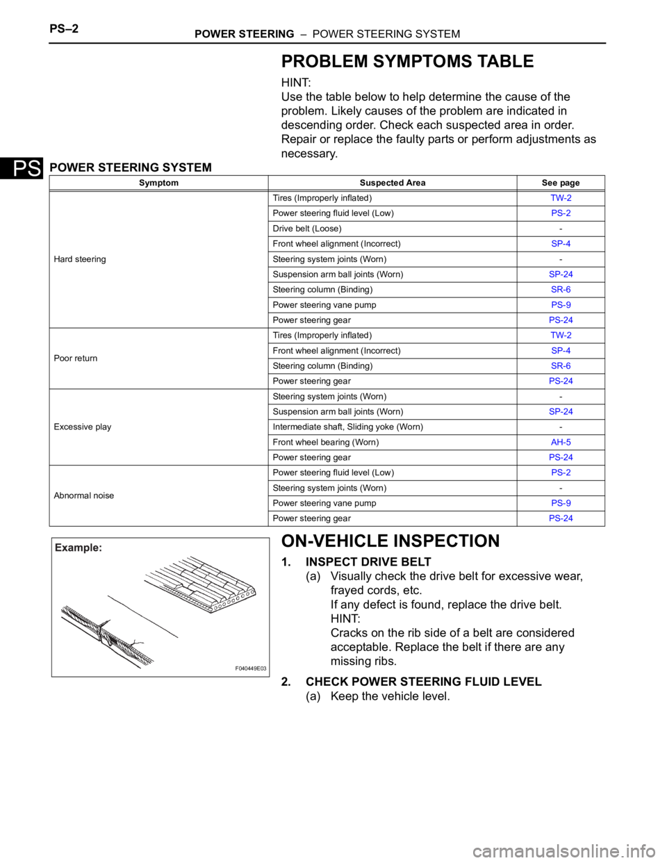
(a) Visually check the drive belt for excessive wear,
frayed cords, etc.
If any defect is found, replace the drive belt.
HINT:
Cracks on the rib side of a belt are considered
acceptable. Replace the belt if there are any
missing ribs.
2. CHECK POWER STEERING FLUID LEVEL
(a) Keep the vehicle level.
Symptom Suspected Area See page
Hard steeringTires (Improperly inflated)TW-2
Power steering fluid level (Low)PS-2
Drive belt (Loose) -
Front wheel alignment (Incorrect)SP-4
Steering system joints (Worn) -
Suspension arm ball joints (Worn)SP-24
Steering column (Binding)SR-6
Power steering vane pumpPS-9
Power steering gearPS-24
Poor returnTires (Improperly inflated)TW-2
Front wheel alignment (Incorrect)SP-4
Steering column (Binding)SR-6
Power steering gearPS-24
Excessive playSteering system joints (Worn) -
Suspension arm ball joints (Worn)SP-24
Intermediate shaft, Sliding yoke (Worn) -
Front wheel bearing (Worn)AH-5
Power steering gearPS-24
Abnormal noisePower steering fluid level (Low)PS-2
Steering system joints (Worn) -
Power steering vane pumpPS-9
Power steering gearPS-24
F040449E03