2007 TOYOTA SIENNA ignition
[x] Cancel search: ignitionPage 343 of 3000

2GR-FE ENGINE CONTROL SYSTEM – SFI SYSTEMES–17
ES
REGISTRATION
NOTICE:
The Vehicle Identification Number (VIN) must be input
into the replacement ECM.
HINT:
The VIN is a 17-digit alphanumeric vehicle identification
number. The intelligent tester is required to register the VIN.
1. INPUT INSTRUCTIONS
(a) The general VIN input instructions using the
intelligent tester are shown below:
(b) The arrow buttons (UP, DOWN, RIGHT and LEFT)
and numerical buttons (0 to 9) are used to input the
VIN.
(c) Cursor Operation
To move the cursor around the tester screen, press
the RIGHT and LEFT buttons.
(d) Alphabetical Character Input
(1) Press the UP and DOWN buttons to select the
desired alphabetical character.
(e) Numerical Character Input
(1) Press the numerical button corresponding to
the number that you want to input.
HINT:
Numerical characters can be selected by using
the UP and DOWN buttons.
(f) Correction
(1) When correcting the input character(s), put the
cursor onto the character using the RIGHT and
LEFT buttons.
(2) Select or input the correct character using the
UP and DOWN buttons, or the numerical
buttons.
(g) Finishing Input Operation
(1) Make sure that the input VIN matches the
vehicle VIN after input.
(2) Press the ENTER button on the tester.
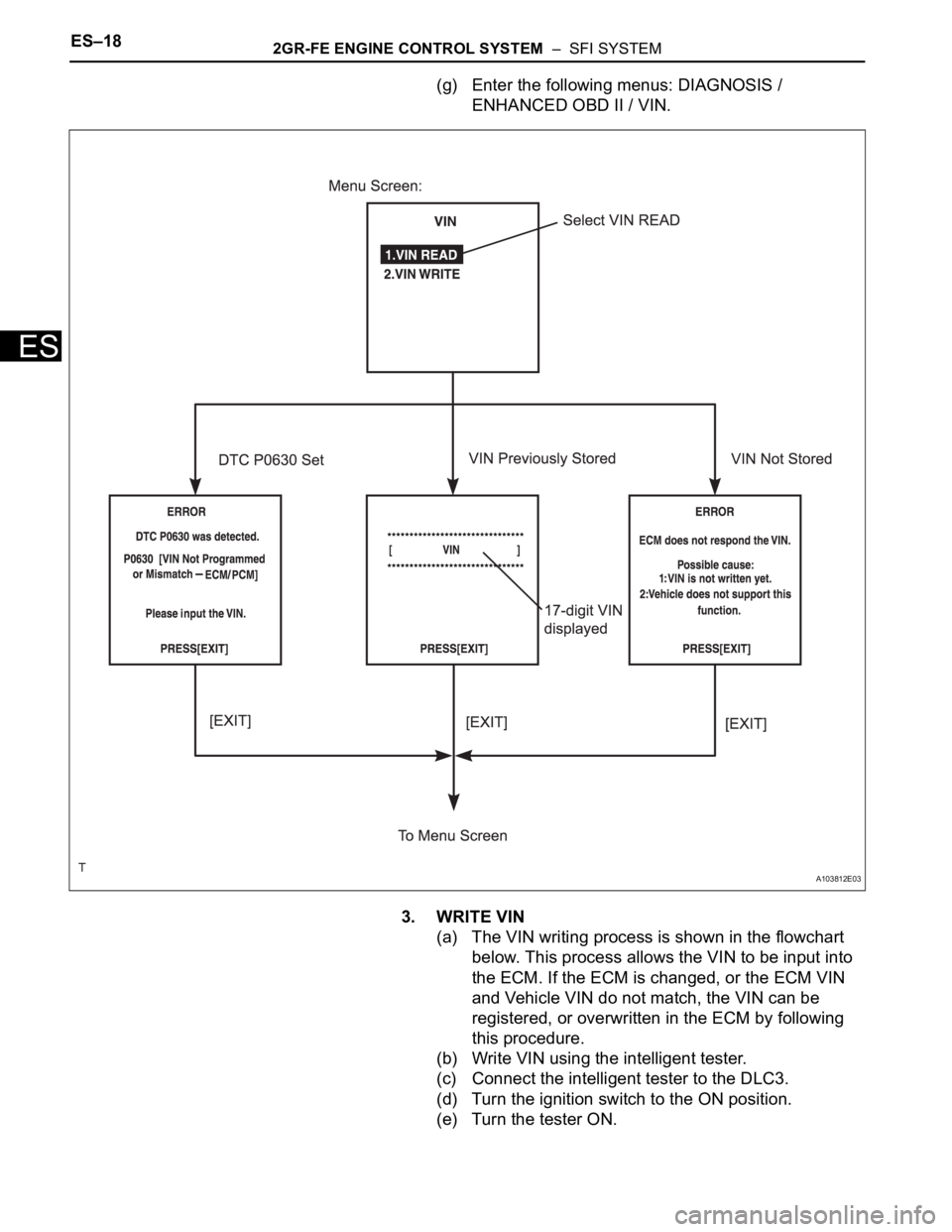
2. READ VIN (Vehicle Identification Number)
(a) The VIN reading process is shown in the flowchart
below. Reading the VIN stored in the ECM is
necessary when comparing it to the VIN provided
with the vehicle.
(b) Read the VIN using the intelligent tester.
(c) Check the vehicle's VIN.
(d) Connect the intelligent tester to the DLC3.
(e) Turn the ignition switch to the ON position.
(f) Turn the tester ON.
Page 344 of 3000

ES–182GR-FE ENGINE CONTROL SYSTEM – SFI SYSTEM
ES
(g) Enter the following menus: DIAGNOSIS /
ENHANCED OBD II / VIN.
3. WRITE VIN
(a) The VIN writing process is shown in the flowchart
below. This process allows the VIN to be input into
the ECM. If the ECM is changed, or the ECM VIN
and Vehicle VIN do not match, the VIN can be
registered, or overwritten in the ECM by following
this procedure.
(b) Write VIN using the intelligent tester.
(c) Connect the intelligent tester to the DLC3.
(d) Turn the ignition switch to the ON position.
(e) Turn the tester ON.
A103812E03
Page 348 of 3000

ES–222GR-FE ENGINE CONTROL SYSTEM – SFI SYSTEM
ES
CHECKING MONITOR STATUS
The purpose of the monitor result (mode 06) is to allow
access to the results for on-board diagnostic monitoring tests
of specific components/systems that are not continuously
monitored. Examples are catalyst, evaporative emission
(EVAP) and thermostat.
The monitor result allows the OBD II scan tool to display the
monitor status, test value, minimum test limit and maximum
test limit. These data are displayed after the vehicle has been
driven to run the monitor.
When the test value is not between the minimum test limit
and maximum test limit, the ECM (PCM) interprets this as a
malfunction. When the component is not malfunctioning, if the
difference of the test value and test limit is very small, the
component will malfunction in the near future.
Perform the following instructions to view the monitor status.
Although the Lexus diagnostic tester is used in the following
instructions, it can be checked using a generic OBD II scan
tool. Refer to your scan tool operator's manual for specific
procedures.
1. PERFORM MONITOR DRIVE PATTERN
The monitor results and test values can be checked with
the OBD II scan tool or the intelligent tester. The engine
control module (ECM) monitors the emissions-related
components such as the thermostat, catalyst converter
and evaporative emissions (EVAP), and determines
whether they are functioning normally or not. When
monitoring is finished, the ECM stores the monitor
results and the test values. The monitor result indicates
whether the component is functioning normally or not.
The test value is the value that was used to determine
the monitor result. If the test value is outside of the test
limit (malfunction criterion), the ECM determines the
component is malfunctioning. Some emissions-related
components have multiple test values to determine
monitor result. If one of these test values is outside of the
test limit, the ECM determines the component is
malfunctioning.
(a) Connect the intelligent tester to the DLC3.
(b) Start the engine and turn the tester on.
(c) Clear the DTCs.
(d) Run the vehicle in accordance with the applicable
drive pattern described in READINESS MONITOR
DRIVE PATTERN (See page ES-22). DO NOT turn
the ignition switch off.
NOTICE:
The test results will be lost if the ignition switch
is turned off.
Page 353 of 3000

2GR-FE ENGINE CONTROL SYSTEM – SFI SYSTEMES–27
ES
Contents:
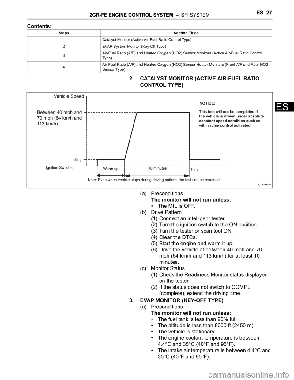
2. CATALYST MONITOR (ACTIVE AIR-FUEL RATIO
CONTROL TYPE)
(a) Preconditions
The monitor will not run unless:
• The MIL is OFF.
(b) Drive Pattern
(1) Connect an intelligent tester.
(2) Turn the ignition switch to the ON position.
(3) Turn the tester or scan tool ON.
(4) Clear the DTCs.
(5) Start the engine and warm it up.
(6) Drive the vehicle at between 40 mph and 70
mph (64 km/h and 113 km/h) for at least 10
minutes.
(c) Monitor Status
(1) Check the Readiness Monitor status displayed
on the tester.
(2) If the status does not switch to COMPL
(complete), extend the driving time.
3. EVAP MONITOR (KEY-OFF TYPE)
(a) Preconditions
The monitor will not run unless:
• The fuel tank is less than 90% full.
• The altitude is less than 8000 ft (2450 m).
• The vehicle is stationary.
• The engine coolant temperature is between
4.4
C and 35C (40F and 95F).
• The intake air temperature is between 4.4
C and
35
C (40F and 95F).
Steps Section Titles
1 Catalyst Monitor (Active Air-Fuel Ratio Control Type)
2 EVAP System Monitor (Key-Off Type)
3Air-Fuel Ratio (A/F) and Heated Oxygen (HO2) Sensor Monitors (Active Air-Fuel Ratio Control
Ty p e )
4Air-Fuel Ratio (A/F) and Heated Oxygen (HO2) Sensor Heater Monitors (Front A/F and Rear HO2
Sensor Type)
A079199E84
Page 354 of 3000

ES–282GR-FE ENGINE CONTROL SYSTEM – SFI SYSTEM
ES
• Vehicle was driven in the city area (or on free-
way) for 10 minutes or more.
(b) Monitor Conditions
(1) Turn the ignition switch off and wait for 6 hours.
HINT:
Do not start the engine until checking Readiness
Monitor status. If the engine is started, the step
described above must be repeated.
(c) Monitor Status
(1) Connect an intelligent tester to the DLC3.
(2) Turn the ignition switch to the ON position.
(3) Turn the tester or scan tool ON.
(4) Check the Readiness Monitor status displayed
on the tester or scan tool.
If the status does not switch to COMPL
(complete), restart the engine, make sure that
the preconditions have been met, and then
perform the Monitor Conditions again.
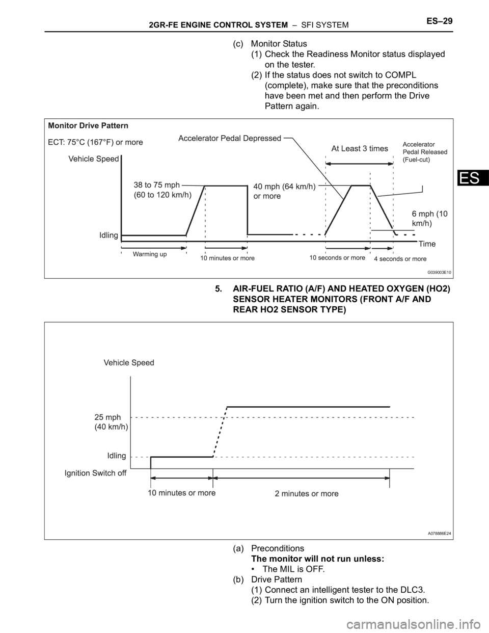
4. A/F SENSOR AND HO2S MONITORS
(a) Preconditions
The monitor will not run unless:
• 2 minutes or more have elapsed since the engine
was started.
• The Engine Coolant Temperature (ECT) is 75
C
(167
F) or more.
• Cumulative driving time at a vehicle speed of 30
mph (48 km/h) or more exceeds 6 minutes.
• Air-fuel ratio feedback control is performed.
• Fuel-cut control is performed for 8 seconds or
more (for the Rear HO2 Sensor Monitor).
(b) Drive Pattern for front A/F sensor and HO2 sensor.
(1) Connect an intelligent tester to the DLC3.
(2) Turn the ignition switch to the ON position.
(3) Turn the tester ON.
(4) Clear the DTCs.
(5) Start the engine, and warm it up until the ECT
reaches 75
C (167F) or higher.
(6) Drive the vehicle at 38 mph (60 km/h) or more
for at least 10 minutes.
(7) Change the transmission to the 2nd gear.
(8) Accelerate the vehicle to 40 mph (64 km/h) or
more by depressing the accelerator pedal for at
least 10 seconds (Procedure "A").
(9) Soon after performing procedure "A" above,
release the accelerator pedal for at least 4
seconds without depressing the brake pedal, in
order to execute fuel-cut control (Procedure "B").
(10) Allow the vehicle to decelerate until the vehicle
speed declines to less than 6 mph (10 km/h)
(Procedure "C").
(11) Repeat procedures from "A" through "C" above
at least 3 times in one driving cycle.
Page 355 of 3000

2GR-FE ENGINE CONTROL SYSTEM – SFI SYSTEMES–29
ES
(c) Monitor Status
(1) Check the Readiness Monitor status displayed
on the tester.
(2) If the status does not switch to COMPL
(complete), make sure that the preconditions
have been met and then perform the Drive
Pattern again.
5. AIR-FUEL RATIO (A/F) AND HEATED OXYGEN (HO2)
SENSOR HEATER MONITORS (FRONT A/F AND
REAR HO2 SENSOR TYPE)
(a) Preconditions
The monitor will not run unless:
• The MIL is OFF.
(b) Drive Pattern
(1) Connect an intelligent tester to the DLC3.
(2) Turn the ignition switch to the ON position.
G039003E10
A078886E24
Page 357 of 3000

2GR-FE ENGINE CONTROL SYSTEM – SFI SYSTEMES–31
ES
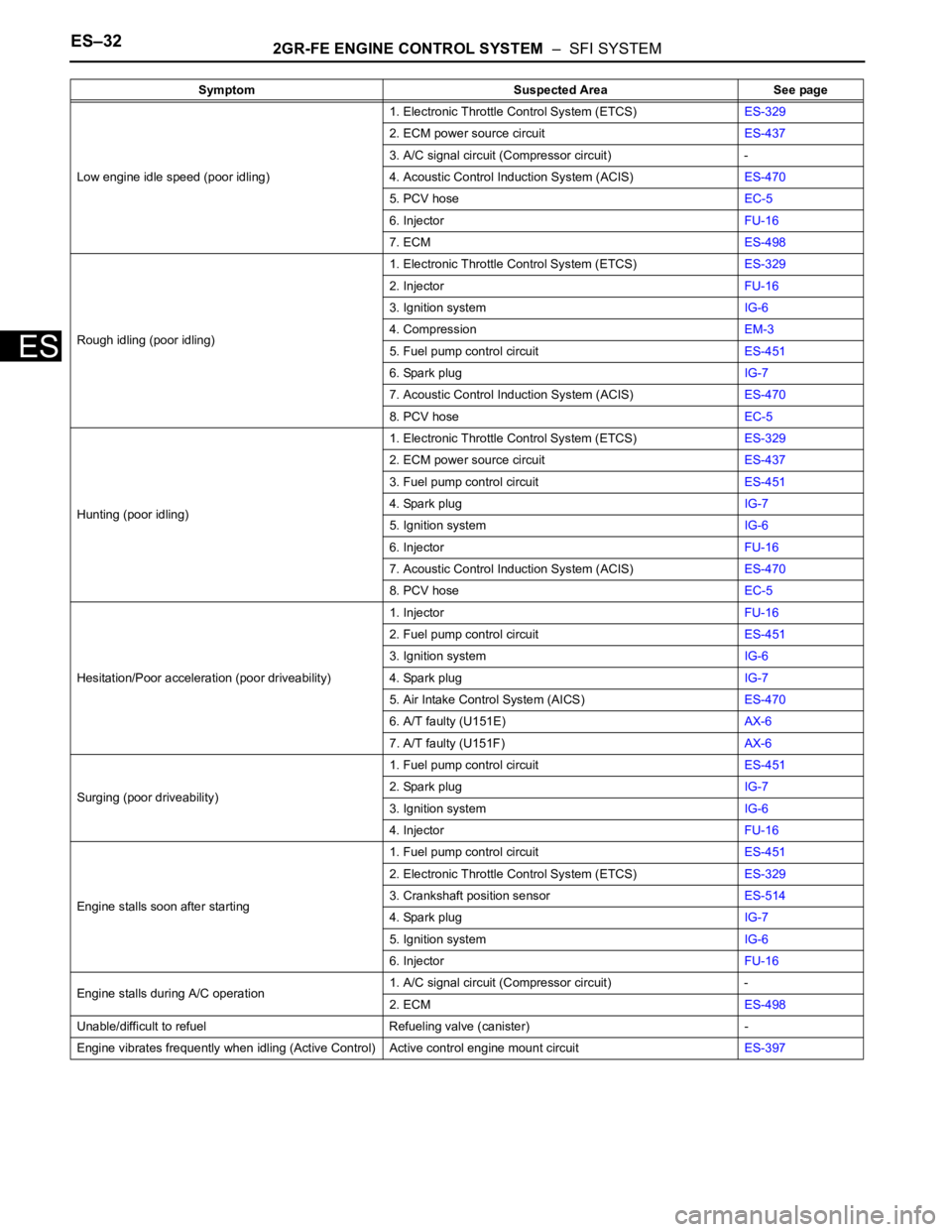
PROBLEM SYMPTOMS TABLE
HINT:
When a malfunction is not confirmed by a DTC (Diagnostic
Trouble Code) check and the cause of problem cannot be
identified through a basic inspection, troubleshoot according
to the priority order indicated in the table below.
SFI SYSTEM
Symptom Suspected Area See page
Engine does not crank (does not start)1. Immobilizer systemEI-2
2. StarterST-7
3. STARTER RelayST-14
4. Cranking holding function circuitES-461
No initial combustion (does not start)1. ECM power source circuitES-437
2. Ignition systemIG-5
3. Fuel pump control circuitES-451
4. InjectorFU-16
5. VC output circuitES-444
6. ECMES-498
Difficult to start (engine cranks normally)1. Electronic Throttle Control System (ETCS)ES-329
2. Fuel pump control circuitES-451
3. Ignition systemIG-5
4. Spark plugIG-7
5. CompressionEM-3
6. InjectorFU-16
7. VC output circuitES-444
Difficult to start with cold engine1. Cranking holding function circuitES-461
2. Electronic Throttle Control System (ETCS)ES-329
3. Fuel pump control circuitES-451
4. Spark plugIG-7
5. Ignition systemIG-6
6. InjectorFU-16
7. Engine coolant temperature sensorES-516
Difficult to start with hot engine1. Cooling fan systemCO-4
2. Cranking holding function circuitES-461
3. Electronic Throttle Control System (ETCS)ES-329
4. Fuel pump control circuitES-451
5. Spark plugIG-7
6. Ignition systemIG-5
7. InjectorFU-16
8. Engine coolant temperature sensorES-516
High engine idle speed (poor idling)1. Electronic Throttle Control System (ETCS)ES-329
2. ECM power source circuitES-437
3. A/C signal circuit (Compressor circuit) -
4. Acoustic Control Induction System (ACIS)ES-470
5. PCV hoseEC-15
6. ECMES-498
Page 358 of 3000

ES–322GR-FE ENGINE CONTROL SYSTEM – SFI SYSTEM
ES
Low engine idle speed (poor idling)1. Electronic Throttle Control System (ETCS)ES-329
2. ECM power source circuitES-437
3. A/C signal circuit (Compressor circuit) -
4. Acoustic Control Induction System (ACIS)ES-470
5. PCV hoseEC-5
6. InjectorFU-16
7. ECMES-498
Rough idling (poor idling)1. Electronic Throttle Control System (ETCS)ES-329
2. InjectorFU-16
3. Ignition systemIG-6
4. CompressionEM-3
5. Fuel pump control circuitES-451
6. Spark plugIG-7
7. Acoustic Control Induction System (ACIS)ES-470
8. PCV hoseEC-5
Hunting (poor idling)1. Electronic Throttle Control System (ETCS)ES-329
2. ECM power source circuitES-437
3. Fuel pump control circuitES-451
4. Spark plugIG-7
5. Ignition systemIG-6
6. InjectorFU-16
7. Acoustic Control Induction System (ACIS)ES-470
8. PCV hoseEC-5
Hesitation/Poor acceleration (poor driveability)1. InjectorFU-16
2. Fuel pump control circuitES-451
3. Ignition systemIG-6
4. Spark plugIG-7
5. Air Intake Control System (AICS)ES-470
6. A/T faulty (U151E)AX-6
7. A/T faulty (U151F)AX-6
Surging (poor driveability)1. Fuel pump control circuitES-451
2. Spark plugIG-7
3. Ignition systemIG-6
4. InjectorFU-16
Engine stalls soon after starting1. Fuel pump control circuitES-451
2. Electronic Throttle Control System (ETCS)ES-329
3. Crankshaft position sensorES-514
4. Spark plugIG-7
5. Ignition systemIG-6
6. InjectorFU-16
Engine stalls during A/C operation1. A/C signal circuit (Compressor circuit) -
2. ECMES-498
Unable/difficult to refuel Refueling valve (canister) -
Engine vibrates frequently when idling (Active Control) Active control engine mount circuitES-397 Symptom Suspected Area See page