Page 199 of 3000
SS–12SERVICE SPECIFICATIONS – 2GR-FE ENGINE MECHANICAL
SS
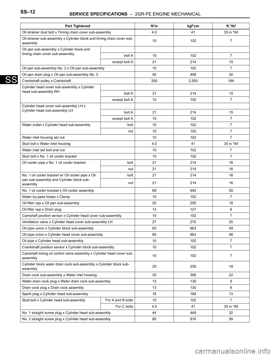
Oil strainer stud bolt x Timing chain cover sub-assembly 4.0 41 35 in.*lbf
Oil strainer sub-assembly x Cylinder block and timing chain cover sub-
assembly10 102 7
Oil pan sub-assembly x Cylinder block and
timing chain cover sub-assembly
bolt A 10 102 7
except bolt A 21 214 15
Oil pan sub-assembly No. 2 x Oil pan sub-assembly 10 102 7
Oil pan drain plug x Oil pan sub-assembly No. 2 40 408 30
Crankshaft pulley x Crankshaft 250 2,550 184
Cylinder head cover sub-assembly x Cylinder
head sub-assembly RH
bolt A 21 214 15
except bolt A 10 102 7
Cylinder head cover sub-assembly LH x
Cylinder head sub-assembly LH
bolt A 21 214 15
except bolt A 10 102 7
Water outlet x Cylinder head sub-assembly bolt 10 102 7
nut 10 103 7
Water inlet housing set nut 10 102 7
Stud bolt x Water inlet housing 4.0 41 35 in.*lbf
Water inlet set bolt and nut 10 102 7
Stud bolt x No. 1 oil cooler bracket 10 102 7
Oil cooler pipe x No. 1 oil cooler bracket bolt 21 214 16
nut 21 214 16
No. 1 oil cooler bracket w/ Oil cooler pipe x Oil
pan sub-assembly and Cylinder block sub-
assemblybolt 21 214 16
nut 21 214 16
No. 1 oil cooler bracket x Oil cooler assembly 68 693 50
Water by-pass hoses x Clamp 10 102 7
Oil filter cap x Oil pan sub-assembly 25 255 18
Oil filter cap x Drain plug 13 127 9
Camshaft position sensor x Cylinder head cover sub-assembly 10 1027
Ventilation valve x Cylinder head cover sub-assembly LH 27 275 20
Oil pipe union x Cylinder block sub-assembly 65 663 48
Oil pipe union x Cylinder head cover sub-assembly 65 663 48
Oil pipe x Cylinder head sub-assembly 10 102 7
Crankshaft position sensor x Cylinder block sub-assembly 10 102 7
Camshaft timing oil control valve assembly x Cylinder head cover sub-
assembly10 102 7
Cylinder block water drain cock sub-assembly x Cylinder block sub-
assembly25 255 18
Drain cock sub-assembly x Water inlet housing 30 306 22
Water drain cock plug x Water drain cock sub-assembly 13 130 9
Drain cock plug x Drain cock assembly 13 130 9
Spark plug x Cylinder head sub-assembly 18 184 13
Stud bolt x Cylinder head sub-assembly For A and B bolts 10 102 7
For C bolts 4.0 41 35 in.*lbf
No. 1 straight screw plug x Cylinder head sub-assembly 44 449 32
No. 2 straight screw plug x Cylinder head sub-assembly 80 816 59Part Tightened N*m kgf*cm ft.*lbf
Page 200 of 3000
SERVICE SPECIFICATIONS – 2GR-FE ENGINE MECHANICALSS–13
SS
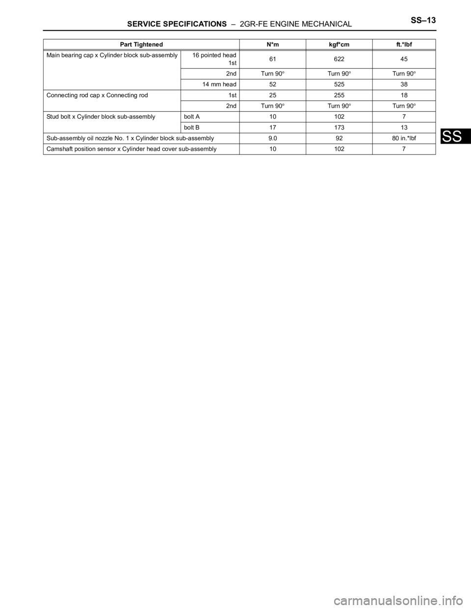
Main bearing cap x Cylinder block sub-assembly 16 pointed head
1st61 622 45
2nd Turn 90
Turn 90Turn 90
14 mm head 52 525 38
Connecting rod cap x Connecting rod 1st 25 255 18
2nd Turn 90
Turn 90Turn 90
Stud bolt x Cylinder block sub-assembly bolt A 10 102 7
bolt B 17 173 13
Sub-assembly oil nozzle No. 1 x Cylinder block sub-assembly 9.0 92 80 in.*lbf
Camshaft position sensor x Cylinder head cover sub-assembly 10 1027 Part Tightened N*m kgf*cm ft.*lbf
Page 214 of 3000

SERVICE SPECIFICATIONS – U151F AUTOMATIC TRANSAXLESS–37
SS
TORQUE SPECIFICATIONS
Part Tightened N*m kgf*cm ft*lbf
Park/neutral position switch Nut 6.9 70 61 in.*lbf
Bolt 5.4 55 48 in.*lbf
Control shaft lever x Control shaft 13 130 9
Shift control cable x Control shaft lever 13 130 9
Transaxle housing x Engine block A bolt 64 653 47
B bolt 46 470 34
C bolt 43 439 32
Torque converter clutch x Drive plate 41 413 30
Flywheel housing under cover x Automatic transaxle 7.8 80 69 in.*lbf
Engine mounting bracket FR x Transaxle 64 653 47
Oil filler tube x Transaxle5.5 56 49 in.*lbf
Control cable bracket No. 1 x Transaxle 12 122 9
Control cable bracket No. 2 x Transaxle 12 122 9
Oil cooler tube clamp x Control cable bracket 5.5 56 49 in.*lbf
Oil cooler inlet tube x Transaxle27 275 20
Oil cooler outlet tube x Transaxle 27 275 20
Starter x Transaxle37 377 27
Starter wire x Starter9.8 100 87 in.*lbf
Wire harness x Transaxle13 133 10
Wire harness clamp x Transaxle8.4 86 74 in.*lbf
Speed sensor (NC) x Transaxle11 11 5 8
Speed sensor (NT) x Transaxle11 11 2 8
Air cleaner x Air cleaner hose5.0 51 44 in.*lbf
Drain plug x Oil pan49 500 36
Transmission wire x Transaxle5.4 55 48 in.*lbf
ATF temperature sensor x Valve body 6.6 67 58 in.*lbf
Oil pan x Transaxle7.8 80 69 in.*lbf
Solenoid valve x Valve body A B bolt 11 110 8
C D bolt 6.6 67 58 in.*lbf
Valve body x Transaxle11 11 0 8
Oil strainer x Valve body11 11 0 8
Floor shift assembly x Body21 214 15
Control cable x Body12 122 9
Transfer x Transaxle69 700 51
Transfer x Transfer stiffener plate RH 34 350 25
Engine mount bracket RR x Transfer stiffener plate RH 34 350 25
Oil cooler assembly x Body Nut
7.0 71 62 in.*lbf
bolt
Differential gear lube apply tube x Transaxle housing 9.8 100 87 in.*lbf
Front planetary gear lock nut
210 to 3502,141 to
3,569155 to 258
Brake apply tube clamp x Transaxle case 5.4 55 48 in.*lbf
Transaxle case No. 1 plug x Transaxle rear cover 7.4 75 65 in.*lbf
Transaxle rear cover x Transaxle case Bolt A 19 190 14
Other bolt 25 250 18
Pawl shaft clamp x Transaxle case 9.8 100 87 in.*lbf
Oil pump assembly x Transaxle case 22 226 16
Page 218 of 3000
SS–24SERVICE SPECIFICATIONS – U151E AUTOMATIC TRANSAXLE
SS
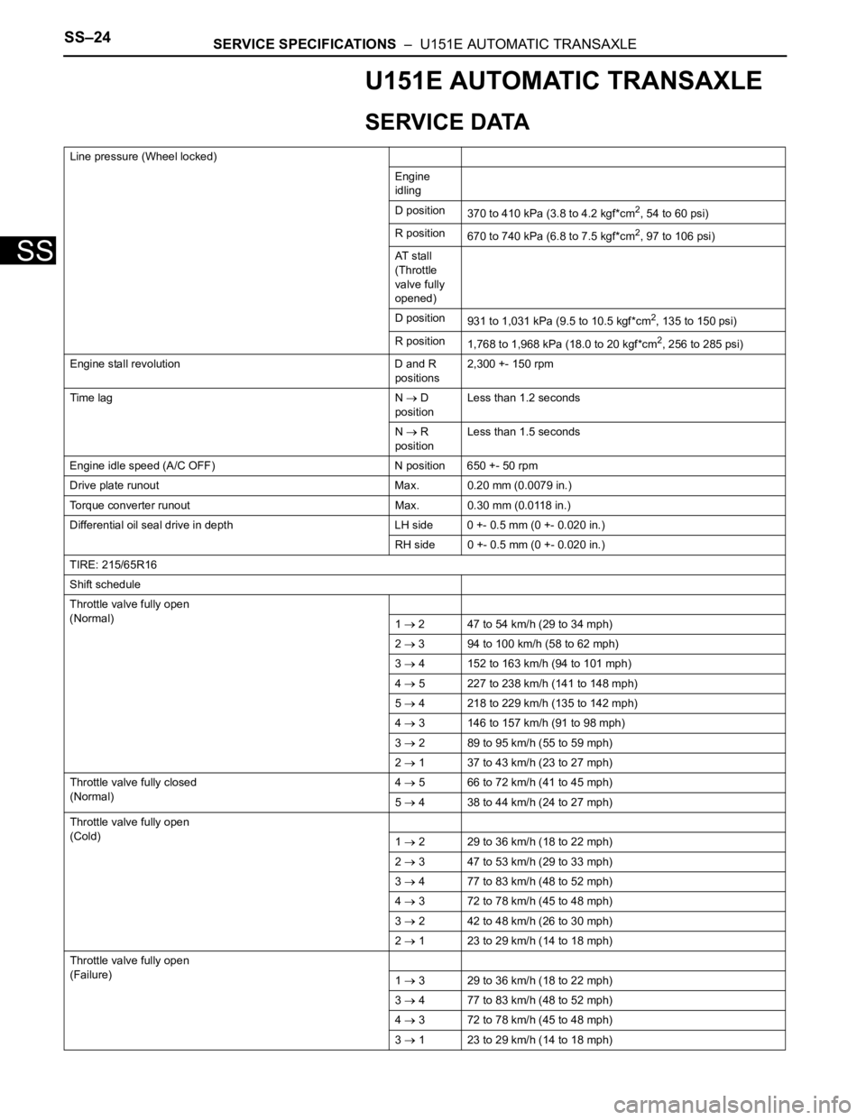
U151E AUTOMATIC TRANSAXLE
SERVICE DATA
Line pressure (Wheel locked)
Engine
idling
D position
370 to 410 kPa (3.8 to 4.2 kgf*cm
2, 54 to 60 psi)
R position
670 to 740 kPa (6.8 to 7.5 kgf*cm
2, 97 to 106 psi)
AT s t a l l
(Throttle
valve fully
opened)
D position
931 to 1,031 kPa (9.5 to 10.5 kgf*cm
2, 135 to 150 psi)
R position
1,768 to 1,968 kPa (18.0 to 20 kgf*cm
2, 256 to 285 psi)
Engine stall revolution D and R
positions2,300 +- 150 rpm
Time lag N
D
positionLess than 1.2 seconds
N
R
positionLess than 1.5 seconds
Engine idle speed (A/C OFF) N position 650 +- 50 rpm
Drive plate runout Max. 0.20 mm (0.0079 in.)
Torque converter runout Max. 0.30 mm (0.0118 in.)
Differential oil seal drive in depth LH side 0 +- 0.5 mm (0 +- 0.020 in.)
RH side 0 +- 0.5 mm (0 +- 0.020 in.)
TIRE: 215/65R16
Shift schedule
Throttle valve fully open
(Normal)
1
2 47 to 54 km/h (29 to 34 mph)
2
3 94 to 100 km/h (58 to 62 mph)
3
4 152 to 163 km/h (94 to 101 mph)
4
5 227 to 238 km/h (141 to 148 mph)
5
4 218 to 229 km/h (135 to 142 mph)
4
3 146 to 157 km/h (91 to 98 mph)
3
2 89 to 95 km/h (55 to 59 mph)
2
1 37 to 43 km/h (23 to 27 mph)
Throttle valve fully closed
(Normal)4
5 66 to 72 km/h (41 to 45 mph)
5
4 38 to 44 km/h (24 to 27 mph)
Throttle valve fully open
(Cold)
1
2 29 to 36 km/h (18 to 22 mph)
2
3 47 to 53 km/h (29 to 33 mph)
3
4 77 to 83 km/h (48 to 52 mph)
4
3 72 to 78 km/h (45 to 48 mph)
3
2 42 to 48 km/h (26 to 30 mph)
2
1 23 to 29 km/h (14 to 18 mph)
Throttle valve fully open
(Failure)
1
3 29 to 36 km/h (18 to 22 mph)
3
4 77 to 83 km/h (48 to 52 mph)
4
3 72 to 78 km/h (45 to 48 mph)
3
1 23 to 29 km/h (14 to 18 mph)
Page 224 of 3000
SERVICE SPECIFICATIONS – U151F AUTOMATIC TRANSAXLESS–31
SS
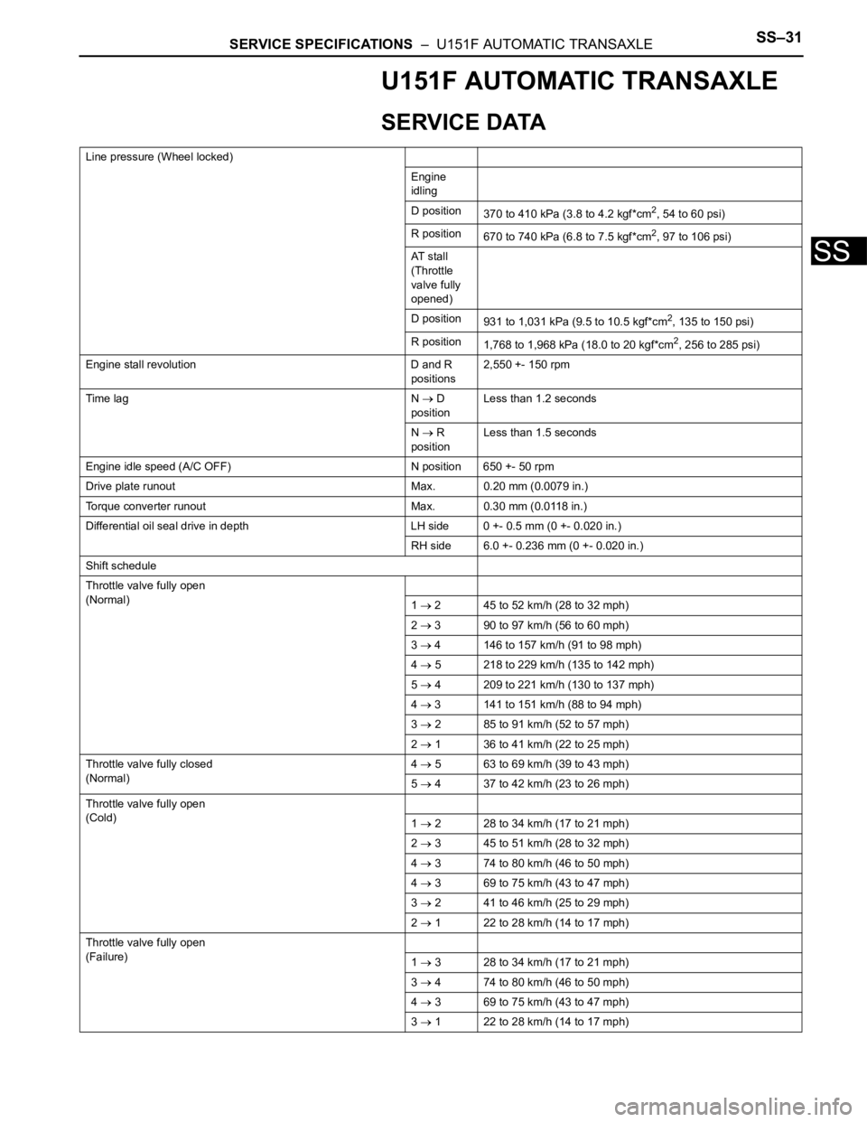
U151F AUTOMATIC TRANSAXLE
SERVICE DATA
Line pressure (Wheel locked)
Engine
idling
D position
370 to 410 kPa (3.8 to 4.2 kgf*cm
2, 54 to 60 psi)
R position
670 to 740 kPa (6.8 to 7.5 kgf*cm
2, 97 to 106 psi)
AT s t a l l
(Throttle
valve fully
opened)
D position
931 to 1,031 kPa (9.5 to 10.5 kgf*cm
2, 135 to 150 psi)
R position
1,768 to 1,968 kPa (18.0 to 20 kgf*cm
2, 256 to 285 psi)
Engine stall revolution D and R
positions2,550 +- 150 rpm
Time lag N
D
positionLess than 1.2 seconds
N
R
positionLess than 1.5 seconds
Engine idle speed (A/C OFF) N position 650 +- 50 rpm
Drive plate runout Max. 0.20 mm (0.0079 in.)
Torque converter runout Max. 0.30 mm (0.0118 in.)
Differential oil seal drive in depth LH side 0 +- 0.5 mm (0 +- 0.020 in.)
RH side 6.0 +- 0.236 mm (0 +- 0.020 in.)
Shift schedule
Throttle valve fully open
(Normal)
1
2 45 to 52 km/h (28 to 32 mph)
2
3 90 to 97 km/h (56 to 60 mph)
3
4 146 to 157 km/h (91 to 98 mph)
4
5 218 to 229 km/h (135 to 142 mph)
5
4 209 to 221 km/h (130 to 137 mph)
4
3 141 to 151 km/h (88 to 94 mph)
3
2 85 to 91 km/h (52 to 57 mph)
2
1 36 to 41 km/h (22 to 25 mph)
Throttle valve fully closed
(Normal)4
5 63 to 69 km/h (39 to 43 mph)
5
4 37 to 42 km/h (23 to 26 mph)
Throttle valve fully open
(Cold)
1
2 28 to 34 km/h (17 to 21 mph)
2
3 45 to 51 km/h (28 to 32 mph)
4
3 74 to 80 km/h (46 to 50 mph)
4
3 69 to 75 km/h (43 to 47 mph)
3
2 41 to 46 km/h (25 to 29 mph)
2
1 22 to 28 km/h (14 to 17 mph)
Throttle valve fully open
(Failure)
1
3 28 to 34 km/h (17 to 21 mph)
3
4 74 to 80 km/h (46 to 50 mph)
4
3 69 to 75 km/h (43 to 47 mph)
3
1 22 to 28 km/h (14 to 17 mph)
Page 250 of 3000
WW–6WIPER AND WASHER – FRONT WIPER MOTOR
WW
INSTALLATION
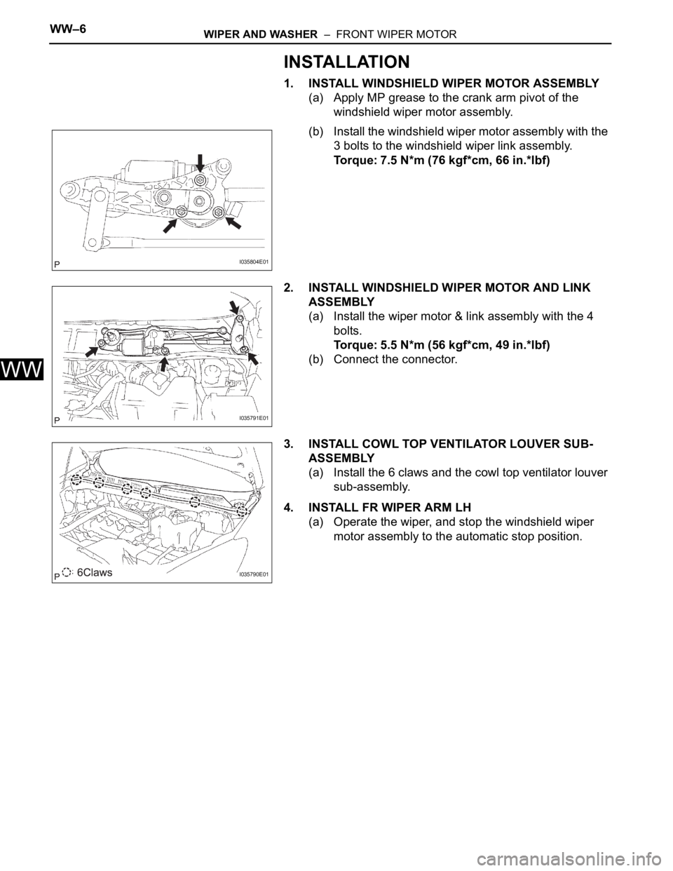
1. INSTALL WINDSHIELD WIPER MOTOR ASSEMBLY
(a) Apply MP grease to the crank arm pivot of the
windshield wiper motor assembly.
(b) Install the windshield wiper motor assembly with the
3 bolts to the windshield wiper link assembly.
Torque: 7.5 N*m (76 kgf*cm, 66 in.*lbf)
2. INSTALL WINDSHIELD WIPER MOTOR AND LINK
ASSEMBLY
(a) Install the wiper motor & link assembly with the 4
bolts.
Torque: 5.5 N*m (56 kgf*cm, 49 in.*lbf)
(b) Connect the connector.
3. INSTALL COWL TOP VENTILATOR LOUVER SUB-
ASSEMBLY
(a) Install the 6 claws and the cowl top ventilator louver
sub-assembly.
4. INSTALL FR WIPER ARM LH
(a) Operate the wiper, and stop the windshield wiper
motor assembly to the automatic stop position.
I035804E01
I035791E01
I035790E01
Page 251 of 3000
WIPER AND WASHER – FRONT WIPER MOTORWW–7
WW
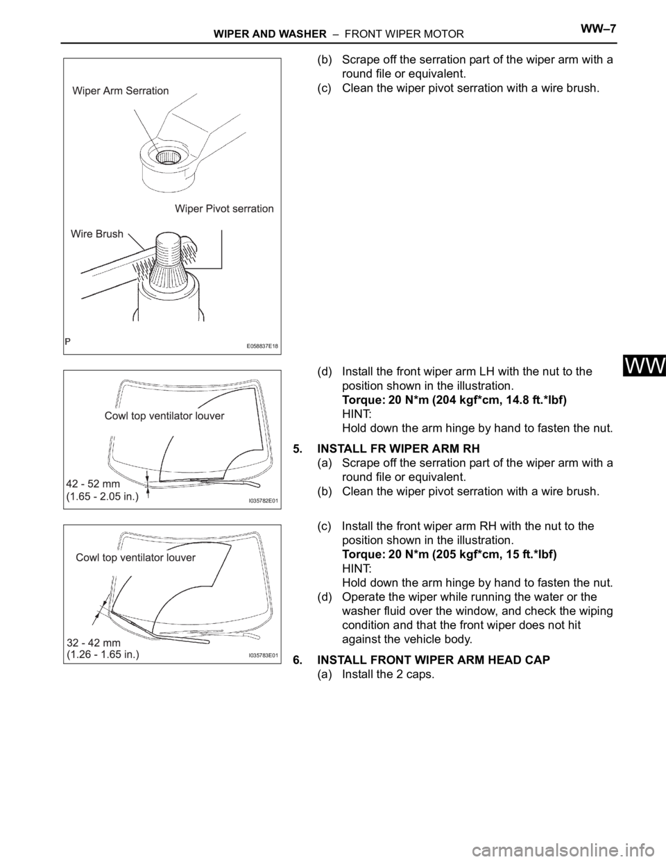
(b) Scrape off the serration part of the wiper arm with a
round file or equivalent.
(c) Clean the wiper pivot serration with a wire brush.
(d) Install the front wiper arm LH with the nut to the
position shown in the illustration.
Torque: 20 N*m (204 kgf*cm, 14.8 ft.*lbf)
HINT:
Hold down the arm hinge by hand to fasten the nut.
5. INSTALL FR WIPER ARM RH
(a) Scrape off the serration part of the wiper arm with a
round file or equivalent.
(b) Clean the wiper pivot serration with a wire brush.
(c) Install the front wiper arm RH with the nut to the
position shown in the illustration.
Torque: 20 N*m (205 kgf*cm, 15 ft.*lbf)
HINT:
Hold down the arm hinge by hand to fasten the nut.
(d) Operate the wiper while running the water or the
washer fluid over the window, and check the wiping
condition and that the front wiper does not hit
against the vehicle body.
6. INSTALL FRONT WIPER ARM HEAD CAP
(a) Install the 2 caps.
E058837E18
I035782E01
I035783E01
Page 265 of 3000
NS–4NAVIGATION – NAVIGATION SYSTEM
NS
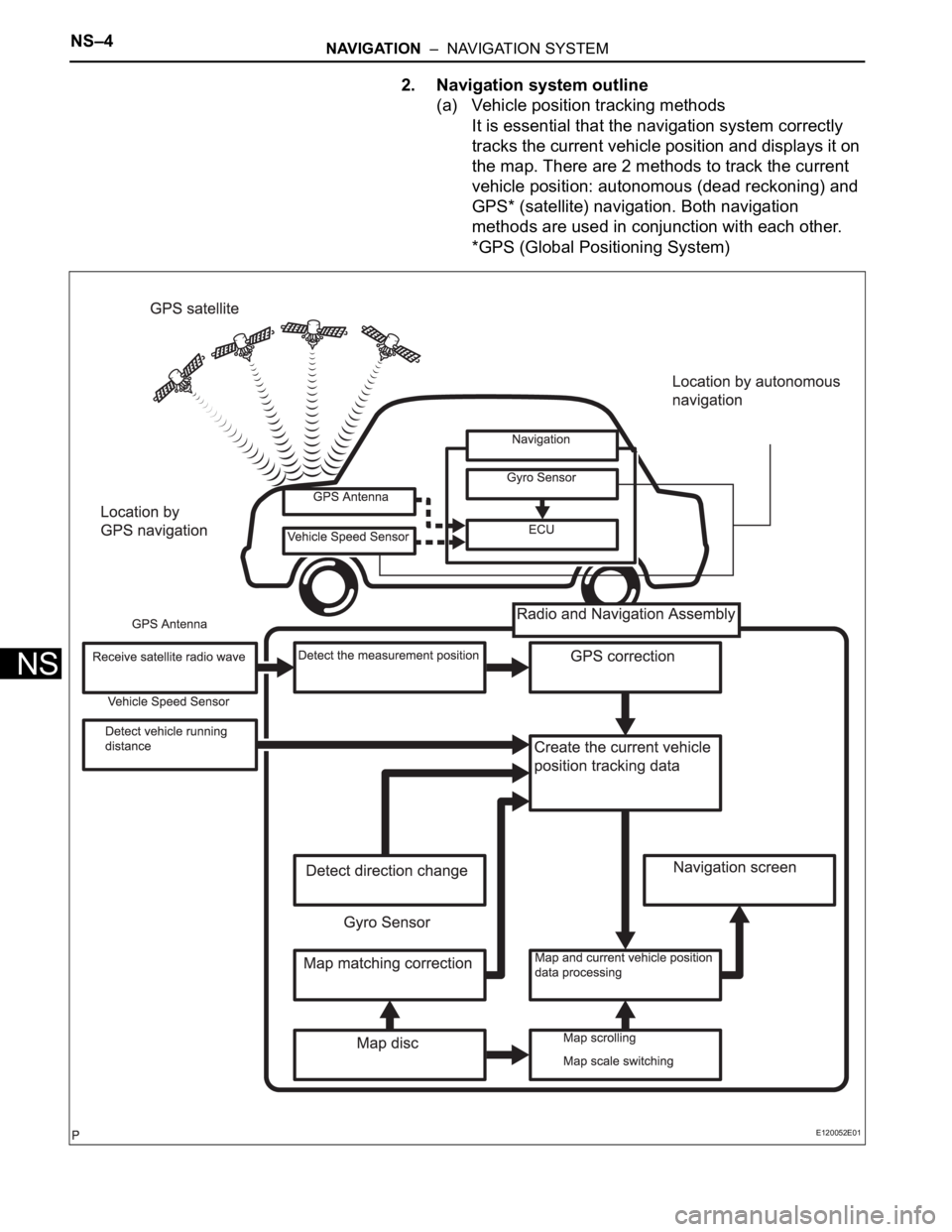
2. Navigation system outline
(a) Vehicle position tracking methods
It is essential that the navigation system correctly
tracks the current vehicle position and displays it on
the map. There are 2 methods to track the current
vehicle position: autonomous (dead reckoning) and
GPS* (satellite) navigation. Both navigation
methods are used in conjunction with each other.
*GPS (Global Positioning System)
E120052E01