Page 9 of 242

Cockpit8
Cockpit
General view
This general view is designed to help you to quickly become familiar
with the instruments, gauges and controls.
Electric power-operated window* . . . . . . . . . . . . . . . . . . . . . . . . . . .
Electric exterior mirror adjustment* . . . . . . . . . . . . . . . . . . . . . . . . . .
Air outlet vents . . . . . . . . . . . . . . . . . . . . . . . . . . . . . . . . . . . . . . . . . . . . .
Multi-functional module* . . . . . . . . . . . . . . . . . . . . . . . . . . . . . . . . . . .
Lever for the multi-functional switch:
− Turn signal light, headlight and parking light, headlight flasher
− Speed regulating system* . . . . . . . . . . . . . . . . . . . . . . . . . . . . . . . . .
Headlight flasher, driver airbag . . . . . . . . . . . . . . . . . . . . . . . . . . . . . .
Instrument cluster: Instruments and in dicator lights . . . . . . . . . . .
Lever for the multi-functional switch:
− Multi-functional indicator* . . . . . . . . . . . . . . . . . . . . . . . . . . . . . . .
− Windshield wiper and wash system . . . . . . . . . . . . . . . . . . . . . . . .
Switch for rear window heater . . . . . . . . . . . . . . . . . . . . . . . . . . . . . . .
Depending on equipment fitted:
− Switch for the ESP* . . . . . . . . . . . . . . . . . . . . . . . . . . . . . . . . . . . . . . .
− Switch for the TCS* . . . . . . . . . . . . . . . . . . . . . . . . . . . . . . . . . . . . . . .
Air outlet vents . . . . . . . . . . . . . . . . . . . . . . . . . . . . . . . . . . . . . . . . . . . . .
Switch for hazard warning lights . . . . . . . . . . . . . . . . . . . . . . . . . . . . .
Indicator light for a switched off front seat passenger airbag* . .
Depending on equipment fitted:
− Operating controls for the heating . . . . . . . . . . . . . . . . . . . . . . . . .
− Operating controls for Climatic* . . . . . . . . . . . . . . . . . . . . . . . . . . .
− Operating controls for Climatronic* . . . . . . . . . . . . . . . . . . . . . . .
Storage compartments on the front passenger side* . . . . . . . . . .
Front passenger airbag* . . . . . . . . . . . . . . . . . . . . . . . . . . . . . . . . . . . . .
Switch for the front seat passenger airbag(s)* . . . . . . . . . . . . . . . . .
Switch depending on equipment fitted:
− Unlocking the boot lid* . . . . . . . . . . . . . . . . . . . . . . . . . . . . . . . . . .
− Interior monitor* . . . . . . . . . . . . . . . . . . . . . . . . . . . . . . . . . . . . . . . .
Fuse box in the dash panel . . . . . . . . . . . . . . . . . . . . . . . . . . . . . . . . . .
Light switch and control dial for the headlight beam range regulation . . . . . . . . . . . . . . . . . . . . . . . . . . . . . . . . . . . . . . . . . . . . . . . . .
Bonnet release lever . . . . . . . . . . . . . . . . . . . . . . . . . . . . . . . . . . . . . . . .
Lever for adjusting the steering wheel . . . . . . . . . . . . . . . . . . . . . . . .
Ignition lock . . . . . . . . . . . . . . . . . . . . . . . . . . . . . . . . . . . . . . . . . . . . . . .
Radio*
Rocker switch for heating on the driver's seat* . . . . . . . . . . . . . . . .
Buttons for central locking* . . . . . . . . . . . . . . . . . . . . . . . . . . . . . . . . .
Depending on equipment fitted:
− Gearshift lever (manual gearbox) . . . . . . . . . . . . . . . . . . . . . . . . . .
− Selector lever (6-speed automatic gearbox)* . . . . . . . . . . . . . . .
Rocker switch for heating on the front passenger seat* . . . . . . . .
Depending on equipment fitted:
− Ashtray* . . . . . . . . . . . . . . . . . . . . . . . . . . . . . . . . . . . . . . . . . . . . . . . .
− Storage compartment . . . . . . . . . . . . . . . . . . . . . . . . . . . . . . . . . . . .
CD changer* . . . . . . . . . . . . . . . . . . . . . . . . . . . . . . . . . . . . . . . . . . . . . . .
Note
•Equipment which is marked * is only standard on certain vehicle model versions or only suppliable as optional equipment for certain models.
•Vehicles with factory-fitted radio, mobi le phone, navigation system, CD player etc. are supplied with separate inst ructions for operating such equipment.
•The arrangement of the controls and switches and the location of some items on right-hand drive models may differ from that shown in ⇒page 7, fig. 1. The symbols on the controls and switches are the same as for left-hand drive models.
A140
A254
A377
A499
A5
48
91
A6126
A79
A8
13
52
A951
A10
143
144
A1177
A1248
A13132
A14
75
77
81
A1568
A16126
A17132
A18
36
40
A19205
A2045, 47
A21172
A2286
A2387
A24
A2558
A2635
A27
89
95
A2858
A29
67
70
A30110
NKO A05F 20 MR08.book Page 8 Thursday, April 19, 2007 11:34 AM
Page 10 of 242

Instruments and Indicator/Warning Lights9
Using the systemSafetyDriving TipsGeneral MaintenanceBreakdown assistanceTechnical Data
Instruments and Indicator/Warning Lights
General view of the instrument cluster
Engine revolutions counter ⇒page 9
Display:
− with digital clock ⇒page 13
− with counter for distance driven ⇒page 11
Speedometer
Coolant temperature gauge* ⇒page 10
Display:
− with Service Interval Display ⇒page 11
− with Multi-functional indicator* ⇒page 13
− with Information display* ⇒page 16
Clock-set button / reset button
Fuel gauge ⇒page 10
When the lights are switched on, the instrument cluster is illuminated.
The version of the instrument cluster can differ depending on the equipment.
Engine revolutions counter
The start of the red zone in the revolutions counter ⇒fig. 2 indicates the maximum permissible engine speed for all gears for an engine which has been run in and operating at a normal temperature. Yo u should shift into the next higher gear before this red zone is reached, or move the selector lever into position D if your car is fitted with an automatic gearbox.
One should shift to the next lower gear at the latest when the engine is no longer running “smoothly”.
Fig. 2 Instrument cluster
A1
A2
A3
A4
A5
A6
A7
A1
NKO A05F 20 MR08.book Page 9 Thursday, April 19, 2007 11:34 AM
Page 11 of 242

Instruments and Indicator/Warning Lights10
Avoid high engine speeds during the running-in period ⇒page 151.
Caution
The needle of the revolutions counter must on no account move into the red zone of the scale - risk of engine damage!
For the sake of the environment
Shifting up early helps you save fuel and reduce the operating noise of your vehicle.
Coolant temperature gauge*
The coolant temperature gauge ⇒page 9, fig. 2 operates only when the ignition is switched on.
In order to avoid any damage to the engine , please pay attention to the following notes regarding the temperature ranges:
Cold range
If the pointer is in the left-hand area of the scale* it means that the engine has not yet reached its operating temperature. Avoid running at high engine speeds, at full throttle and at severe engine loads.
The operating range
The engine has reached its operating temperature as soon as the pointer moves into the mid-range of the scale*. The pointe r may also move further to the right at high engine loads and high outside temperat ures. This is not critical provided the warning symbol in the instrument cluster does not flash.
If the symbol in the instrument cluster flashes it means that either the coolant temperature is too high or the coolant level is too low. Please refer to the guide- lines ⇒page 24, “Coolant temperature/coolant level ”.
WARNING
Pay attention to the warning notes ⇒page 173, “Working in the engine compartment” before opening the bonnet and inspecting the coolant level.
Caution
Additional headlights and other attached co mponents in front of the fresh air inlet impair the cooling efficiency of the coolant. There is then a risk of the engine over-heating at high outside temperatures and high engine loads!
Fuel gauge
The fuel gauge ⇒page 9, fig. 2 only operates when the ignition is switched on.
The fuel tank has a capacity of about 45 litres. The warning symbol in the instru- ment cluster lights up when the pointer reaches the reserve marking. There are now about 7 litres of fuel remaining in the tank. This symbol is a reminder for you, that you must refuel .
The following will be displayed in the information display*:
PLEASE REFUEL
A peep sounds as an additional warning signal.
Caution
Never run the fuel tank completely empty! An irregular fuel supply can result in poor ignition or misfiring. Unburnt fuel may get into the exhaust system and damage the catalytic converter.
A4A7
NKO A05F 20 MR08.book Page 10 Thursday, April 19, 2007 11:34 AM
Page 12 of 242

Instruments and Indicator/Warning Lights11
Using the systemSafetyDriving TipsGeneral MaintenanceBreakdown assistanceTechnical Data
Counter for distance driven
The distance which you have driven with your vehicle is shown in kilometres (km). On certain model versions, the readout is shown in “miles”.
The kilometer counter for distance driven is shown on the display when the ignition is switched off. The trip counter for dist ance driven is shown on the display after switching on the ignition. You can then swit ch over to the counter display with the reset button.
Reset button
By briefly pressing the reset button ⇒page 9, fig. 2 you can switch over from the trip counter to the kilometer counter. In order to recognize which counter for the distance driven is shown on the display at that moment, trip ⇒fig. 3appears after the trip counter.
If you hold the reset button pressed for about 1 second, the trip counter is set back to zero.
If you hold the reset button pressed for longer than 3 seconds, a display regarding the kilometers still to be driven and the days until the following service interval (for this the trip counter is not set back) appears.
Fa ult di spl a y
dEF will appear as a constant text in the display field of the counter for distance driven if there is a fault in the instrument cluster. Have the fault rectified as soon as possible by a specialist workshop.
Warning against excessive speeds*
An acoustic warning signal will sound when the vehicle speed exceeds 120 kilome- tres per hour. The acoustic warning signal will switch off again when the vehicle speed goes below this speed limit.
This function is only valid for some countries.
WARNING
Never seek to adjust the trip counter for distance driven while driving for safety reasons!
Note
On vehicles with information display bo th counters are shown simultaneously on the display.
Service Interval Display
Depending on the equipment installed in the vehicle, the text can differ slightly on the display.
Fig. 3 Display: Counter for distance driven
A6
A6
A6Fig. 4 Service Interval Display: Note
NKO A05F 20 MR08.book Page 11 Thursday, April 19, 2007 11:34 AM
Page 13 of 242

Instruments and Indicator/Warning Lights12
Service Interval Display
A key symbol appears in the counter display for distance driven about 30 days before reaching the due date for the service ⇒page 11, fig. 4. The remaining distance to be driven will be indicated for 10 seconds next to the key symbol and then the remaining number of days to th e due date for the service inspection.
The following will be displayed in the information display*:
SERVICE IN ... KM OR ... DAYS
The kilometre indicator or the days indica tor reduces in steps of 100 km. or days until the service due date is reached.
The following text appears as a flashing key symbol and a text as soon as the due date for the service is reached:
INSP
The following will be displayed in the information display*:
SERVICE NOW
The display disappears within 20 seconds af ter switching on the ignition. The trip counter is also displayed after pressing th e reset button for the trip counter (for more than 1 second).
Display regarding the distance and days until the following service interval
You can have the distance still to be driv en and the days until the following service interval displayed at any time as follows:
•Press reset button for more than 3 seconds.
A key symbol is displayed on the display of the counter for the distance driven. The remaining distance to be driven will be indicated for 10 seconds next to the key symbol and then the remaining number of days to the due date for the service inspection.
Resetting Service Interval Display
We recommend having this resetting performed by a specialist garage.
The specialist garage:
•resets the memory of the display after the appropriate inspection,
•makes an entry in the Service schedule,
•affix the sticker with the entry of the following service interval to the side of the dash panel on the driver's side.
The Service Interval Display can also be reset with the reset button as follows:
•Switch off the ignition, press the reset button of the trip counter for distance driven and hold it down.
•Switch the ignition on and release the reset button. Now turn the reset button to the right. The service interval display is reset.
Caution
We recommend that you do not reset the Service Interval Display yourself other- wise this can result in the service interval display being incorrectly set, which may also result in problems with operation of your vehicle.
Note
•Never reset the display between service intervals otherwise this may result in incorrect readouts.
•information is retained in the Service Interval Display also after the battery of the vehicle is disconnected.
•it is necessary to re-code the Service Interval Display if a new instrument cluster is installed during repair work. This work is carried out by a specialist garage.
•The data displayed is the same after resetting the display with flexible service intervals (QG1) using the reset button as th at for a vehicle with fixed service inter- vals (QG2). We therefore recommend having the Service Interval Display reset only by a Škoda Service Partner who is famili ar with the procedure for resetting the display with a vehicle system tester.
•Please refer to the brochure Service schedule for extensive information about the service intervals.
•It is only possible to reset the Service Interval Display, if a service message or at least a pre-warning is shown on the display of the instrument cluster.
A6
A6
NKO A05F 20 MR08.book Page 12 Thursday, April 19, 2007 11:34 AM
Page 14 of 242

Instruments and Indicator/Warning Lights13
Using the systemSafetyDriving TipsGeneral MaintenanceBreakdown assistanceTechnical Data
Digital clock
A reset button is installed on the left below beside the speedometer for
adjusting the clock ⇒page 9, fig. 2.
Set hours
– Turn the reset button to the left.
Setting minutes
– Turn the reset button to the right.
WARNING
The clock should not be adjusted while driving for safety reasons but only when the vehicle is stationary.
Multi-functional indicator (onboard computer)*
Introduction
The multi-functional indicator appears in the display ⇒fig. 5 or in the information display ⇒page 16, fig. 8 depending on the equipment fitted to your vehicle.
The multi-functional indicator offers you a range of useful information.
Note
In certain national versions the displays appear in the Imperial system of measures.
Memory
The multi-functional indicator is equi pped with two automatic memories. The selected memory is displayed in the middle of the display field ⇒fig. 5.
The data of the single-trip memo ry (memory 1) is shown if a 1 appears in the display. A 2 shown in the display means that data relates to the total distance memory (memory 2).
Switching of the memory takes place when the button ⇒page 14, fig. 6.
Single-trip memory (memory 1)
The single-trip memory collates the driving information from the moment the igni- tion is switched on until it is switched of f. New data will also flow into the calcula- tion of the current driving information if the trip is continued within 2 hours after switching off the ignition. The memory will be is automatically erased, on the other hand, if the trip is interrupted for more than 2 hours.
The outside temperature⇒page 15
Range⇒page 15
Current fuel consumption⇒page 15
Average fuel consumption⇒page 15
Driving time⇒page 16
Distance driven⇒page 16
Average speed⇒page 16
Fig. 5 Instrument cluster: Multi-functional indicator
AB
NKO A05F 20 MR08.book Page 13 Thursday, April 19, 2007 11:34 AM
Page 15 of 242

The total distance driven memory gathers data from any number of indvidual jour- neys up to a total of 100 hours driving or 10")
Instruments and Indicator/Warning Lights14
Total-trip memory (memory 2)
The total distance driven memory gathers data from any number of indvidual jour- neys up to a total of 100 hours driving or 10 000 kilometres driven. The memory is deleted when either of these limits is reached and the calculation starts from anew.
The total-trip memory will not, contrary to the single-trip memory, be deleted after a period of interruption of driving of 2 hours.
Note
All information in the memory is erased if the battery of the vehicle is disconnected.
Using the system
The rocker switch and the button are located in the grip of the
window wiper lever ⇒fig. 6.
Selecting the memory
– Repeated short-term pressing of the button allows one to select
the individual memories.
Selecting the functions
– Press the rocker switch up or do wn. This will cause the individual
functions of the multi-functional indicator to appear in the display
one after the other.
Setting function to zero
– Select the memory you want.
– Press button for more than 1 second.
The following readouts of the selected memory will be set to zero by button :
•average fuel consumption,
•distance driven,
•average speed,
•driving time.
You can only operate the multi-functional indicator when the ignition is switched on. After the ignition is switched on, the fu nction displayed is the one which you last selected before switching off the ignition.
If the outside temperature drops below +4 °C, a snow flake symbol (warning signal for ice on the road) appears with the outside temperature indicator ⇒page 15, fig. 7 and a warning signal* sounds for 10 seconds. The snoke flake symbol draws the attention of the driver to possible black ice formation. The display swicthes back after 10 seconds to the last selected function.
Fig. 6 Multi-functional indicator: Control elements
AAAB
AB
AA
AB
AB
NKO A05F 20 MR08.book Page 14 Thursday, April 19, 2007 11:34 AM
Page 16 of 242

Instruments and Indicator/Warning Lights15
Using the systemSafetyDriving TipsGeneral MaintenanceBreakdown assistanceTechnical Data
Outside temperature
The outside temperature appears in the display when the ignition is switched on.
The correct outside temperature will be indicated with a delay of 5 minutes. If the vehicle is stationary (or driven at a very low speed) the temperature indicated may be slightly higher than the actual outside temperature because of heat radiated by the engine.
If the outside temperature drops below +4 °C, a snow flake symbol (warning signal for ice on the road) appears with the outside temperature indicator ⇒fig. 7 and a warning signal* sounds for 10 seconds.
WARNING
Do not only rely upon the information given on the outside temperature display that there is no ice on the road. Please note that black ice may also be present on the road surface even at temperatures around +4 °C - warning, drive with care!
Note
The outside temperature is not indicating when showing navigation data (guidance to the destination). It must be called up over the menu (valid for vehicles which have a navigation and information display).
Range
The estimated range in kilometres is shown on the display. It indicates the distance you can still drive with your vehicle based on the present level of fuel in the tank for the same style of driving. The readout is shown in steps of 10 km.
The fuel consumption for the last 50 km is taken as a basis for calculating the range. If you drive in a more economical manner from this moment on, the range will be increased accordingly.
You first drive 50 km if the readout is reset (after disconnecting the battery) before a new readout for the range is displayed.
Current fuel consumption
The current fuel consumption level is shown in the display in litres/100 km. This information can help you to adapt your styl e of driving to the fuel consumption you wish to achieve.
The display appears in litres/hour if the vehicle is stationary or driving at a low speed.
Average fuel consumption
The average fuel consumption since the me mory was last erased is shown in the display in litres/100 km ⇒page 13. This information can help you to adapt your style of driving to the fuel co nsumption you wish to achieve.
If you wish to determine the average fuel consumption over a certain period of time you must first erase the memory at the start of the new measurement using the button ⇒page 14, fig. 6. A zero appears in the display for the first 300 m you drive after erasing the memory.
The indicated value will be updated every 5 seconds while you are driving.
Note
The amount of fuel consum ed will not be indicated.
Fig. 7 Multi-functional indicator: the outside temperature
AB
NKO A05F 20 MR08.book Page 15 Thursday, April 19, 2007 11:34 AM
 1
1 2
2 3
3 4
4 5
5 6
6 7
7 8
8 9
9 10
10 11
11 12
12 13
13 14
14 15
15 16
16 17
17 18
18 19
19 20
20 21
21 22
22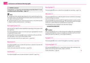 23
23 24
24 25
25 26
26 27
27 28
28 29
29 30
30 31
31 32
32 33
33 34
34 35
35 36
36 37
37 38
38 39
39 40
40 41
41 42
42 43
43 44
44 45
45 46
46 47
47 48
48 49
49 50
50 51
51 52
52 53
53 54
54 55
55 56
56 57
57 58
58 59
59 60
60 61
61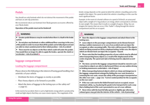 62
62 63
63 64
64 65
65 66
66 67
67 68
68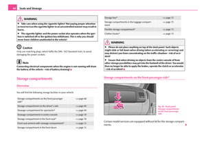 69
69 70
70 71
71 72
72 73
73 74
74 75
75 76
76 77
77 78
78 79
79 80
80 81
81 82
82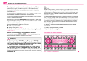 83
83 84
84 85
85 86
86 87
87 88
88 89
89 90
90 91
91 92
92 93
93 94
94 95
95 96
96 97
97 98
98 99
99 100
100 101
101 102
102 103
103 104
104 105
105 106
106 107
107 108
108 109
109 110
110 111
111 112
112 113
113 114
114 115
115 116
116 117
117 118
118 119
119 120
120 121
121 122
122 123
123 124
124 125
125 126
126 127
127 128
128 129
129 130
130 131
131 132
132 133
133 134
134 135
135 136
136 137
137 138
138 139
139 140
140 141
141 142
142 143
143 144
144 145
145 146
146 147
147 148
148 149
149 150
150 151
151 152
152 153
153 154
154 155
155 156
156 157
157 158
158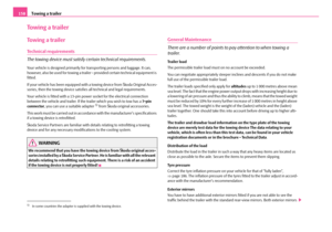 159
159 160
160 161
161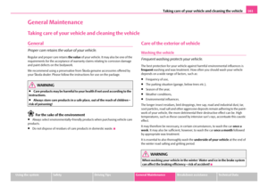 162
162 163
163 164
164 165
165 166
166 167
167 168
168 169
169 170
170 171
171 172
172 173
173 174
174 175
175 176
176 177
177 178
178 179
179 180
180 181
181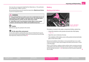 182
182 183
183 184
184 185
185 186
186 187
187 188
188 189
189 190
190 191
191 192
192 193
193 194
194 195
195 196
196 197
197 198
198 199
199 200
200 201
201 202
202 203
203 204
204 205
205 206
206 207
207 208
208 209
209 210
210 211
211 212
212 213
213 214
214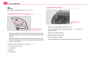 215
215 216
216 217
217 218
218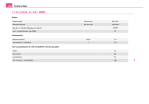 219
219 220
220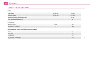 221
221 222
222 223
223 224
224 225
225 226
226 227
227 228
228 229
229 230
230 231
231 232
232 233
233 234
234 235
235 236
236 237
237 238
238 239
239 240
240 241
241