Page 41 of 242

Unlocking and locking40
Interior monitor* and Towing protection*
The interior monitor and the towing protection detect movements
inside the vehicle interior and then trigger the alarm.
The interior monitor and the towing protection are operated with the
button . You can switch the interior monitor and the towing protec-
tion off if there is a possibility that movements from (e.g. children or
animals) inside the vehicle interior or if the vehicle must be transported
(e.g. by train or ship) or towed, might trigger the alarm.
Switch off the interior monitor and towing protection
– Switch off the ignition.
– Press the button on the driver door ⇒fig. 27.
– Lock the vehicle within 30 seconds. The interior monitor and the
towing protection are switched off.
The interior monitor and the towing protection are switched on again automatically the next time the car is locked.
Note
•You can also switch off the interior moni tor and the towing protection, by deac- tivating the safe securing system ⇒page 34.
•When the ignition key is removed or a door is opened, the symbol in the button lights up red.
•Lighting up of the symbol in the button does not confirm that the interior monitor and the towing protection are switched on.
Power windows*
Switch for power windowsFig. 27 Interior monitor pushbutton
Fig. 28 Buttons on the driver's door
Fig. 29 Switch in the rear door
NKO A05F 20 MR08.book Page 40 Thursday, April 19, 2007 11:34 AM
Page 42 of 242

Unlocking and locking41
Using the systemSafetyDriving TipsGeneral MaintenanceBreakdown assistanceTechnical Data
The power windows operate only when ignition is switched on.
Opening a window
– A window is opened by pres sing lightly on the respective butto n in the
door. The process stops when one releases the button.
– Additionally you can open the window automatically (fully opened) by
pressing the button up to the stop. Renewed pressing of the button
causes the window to stop immediately.
Closing a window
– A window is closed through pulling lightly on the respective button in
the door. The closing process stop s when one releases the button.
– Additionally you can close the window automatically (fully closed) by
pulling the button up to the stop. Renewed pulling of the button
causes the window to stop immediately.
The switches for the individual windows are located in the operating part in the driver's door ⇒page 40, fig. 28, front passenger door and in the rear doors*.
If the buttons for the rear doors are deactivated, the indicator light in the safety switch lights up.
The switch for the power window in th e operating part in the driver's door
Button for the power window in the driver's door
Button for the power window in the front passenger's door
Button for the power window in the rear door on the right*
Button for the power window in the rear door on the left*
Safety pushbutton*
Safety pushbutton*
You can deactivate the switches for power windows at rear doors by pressing the safety pushbutton ⇒page 40, fig. 28. The buttons for power windows at rear doors are activated again by pressing the safety pushbutton again.
WARNING
•If you lock the vehicle from the outside, do not leave any person in the vehicle since it is no longer possible to open the windows from the inside in an emergency.
•The system is fitted with a force limiter. The closing process will be stop if an obstruction is detected and the window will open again. You should then take particular care when closing the windows! You may otherwise suffer severe injuries as a result of getting an arm, for example, jammed in the window!
•It is recommended to deactivate the electrically operated power windows in the rear doors (safety pushbutton) ⇒page 40, fig. 28 when children are being transported on the rear seats.
•In the event of a freezing up of the wi ndscreen, first of all eliminate the ice ⇒ page 164 and then operate the power windows otherwise the power window mechanism could be damaged.
Note
•After switching the ignition off, it is still possible to open or close the windows for a further 10 minutes. The automatic closing and opening functions will not operate during this time. The power windows are switched off completely once you open the driver or front passenger door.
•When driving always use the existing he ating, air conditioning and ventilation system for ventilating the interior of the vehicle. If the windows are opened, dust as well as other dirt can get into the vehicle an d in addition the wind noise is more at certain speeds.
Force limiter of the power windows
The electrically operated power windows are fitted with a force limiter. It reduces the risk of bruises or injuri es when closing the windows.
If there is an obstacle, the closing process is stopped and the window goes down by several centimeters.
AS
AA
AB
AC
AD
AS
ASAS
AS
NKO A05F 20 MR08.book Page 41 Thursday, April 19, 2007 11:34 AM
Page 43 of 242

Unlocking and locking42
You must try to close the window again within 10 seconds, even if the obstacle was not yet removed, the closing process is stoppe d. During this time it is not possible to automatically close the window. The force limiter is still switched on.
The force limiter is only switched off, if you attempt to close the window within the next 10 seconds - the window closes now with full strength!
If you wait longer than 10 seconds, th e force limiter is switched on again.
WARNING
You should take particular care when closing the windows! You may other- wis e su ffe r s ev e re inj uri e s a s a re sul t o f g e t tin g an a rm , fo r e xa m pl e, j am m e d in the window!
Window convenience operation
You can open and close the window with power windows as follows
when unlocking and locking the vehicle.
Opening windows with the key
– Turn the key in the lock of the driver door into the opening position
and hold it until all the windows are open.
Closing windows with the key
– Turn the key in the lock of the driver door into the closing position and
hold it there until all of the windows are closed.
You can interrupt the opening or closing operation of the windows immediately by releasing the key.
WARNING
•Obstruction protection is not active during the convenience operating feature ⇒ in “Switch for power windows” on page 40.
•You should take particular care when closing the windows! You may otherwise suffer severe injuries as a re sult of getting an arm, for example, jammed in the window!
Operational faults
Electrically operated power windows do not operate
If the battery of the car has been disco nnected and then reconnected, the electri- cally operated power windows do not oper ate. The system must be activated. Proceed as follows in order to re-establish the function:
•turn the key in the lock of the driver d oor into the closing position and hold it there until all of the windows are closed,
•release the key,
•once again insert the key and turn it into the closing position for about 3 seconds.
Operation in winter
Ice accumulating on the surface of the windows during the winter may result in a greater resistance when closing the windows and the window may stop and move back several centimetres
Proceed as follows to close the window fully:
•turn the key in the lock of the driver d oor into the closing position and hold it there until all of the windows are closed,
•repeat this operation until the window stops.
WARNING
•Obstruction protection is not active during the closing of the windows ⇒ in “Switch for power windows” on page 40.
•You should take particular care when closing the windows! You may otherwise suffer severe injuries as a re sult of getting an arm, for example, jammed in the window!
WARNING (continued)
NKO A05F 20 MR08.book Page 42 Thursday, April 19, 2007 11:34 AM
Page 44 of 242

Unlocking and locking43
Using the systemSafetyDriving TipsGeneral MaintenanceBreakdown assistanceTechnical Data
Electric sliding/tilting roof*
Description
The sliding/tilting roof is operated by means of the control dial ⇒fig. 30 and only functions when the ignition is switched on . The control dial has a number of fixed positions.
After switching the ignition off, it is still possible to open or close the sliding/tilting roof for a further 10 minutes. It is no long er possible to operate the sliding/tilting roof after opening or closing on e of the front doors, however.
Note
•If the battery has been disconnected and reconnected, it is possible that the sliding/tilting roof does not close fully. He re you have to set the control dial to the switch position and press it forward for about 10 seconds.
•It is necessary afte r each emergency operation (using Allen key) to move the sliding/tilting roof into the basic position . Here you have to set the control dial to the switch position and press it forward for about 10 seconds.
Opening and tilting
Comfort position
– Turn the switch to position ⇒fig. 30.
Opening roof fully
– Turn the switch to position and hold it in this position (spring-
tensioned position).
Tilting roof
– Turn the switch to position .
The wind noise in the comfort position is less than when the roof is fully opened.
The sun screen is also opened automatica lly when the roof slides open. You can slide the sun screen into the opened or closed position by hand when the sliding/tilting roof is closed.
Caution
It may be necessary during winter to remo ve any ice and snow in the area of the sliding/tilting roof before opening it in order to prevent damaging the opening mechanism and the seal.
Closing
Sliding closed/closing the sliding/tilting roof
– Turn the switch to position ⇒fig. 30.
Safety closing
The sliding/tilting roof is equipped wi th an overload protection system. The sliding/tilting roof stops and moves back several centimetres when it cannot be closed because there is something in the way (e.g. ice). You can close the sliding/tilting roof completely without overlo ad protection by pressing the switch to
Fig. 30 Control dial for the power sliding/tilting roof
AA
AA
AC
AB
AD
AA
NKO A05F 20 MR08.book Page 43 Thursday, April 19, 2007 11:34 AM
Page 45 of 242

Unlocking and locking44
the position ⇒fig. 30 at the front or rear for as long as it takes for the sliding/tilting roof to shut completely ⇒.
WARNING
Close the sliding/tilting roof carefully - risk of injury!
Convenience operation
You can also close an open sliding/tilting roof from the outside.
– Turn the key in the lock of the driver door into the closing position and
hold until the sliding/tilting roof is closed ⇒.
The closing process stops when one releases the key.
WARNING
Close the sliding/tilting roof carefully - risk of injury! The overload protec- tion system does not function with the convenience closing.
Emergency operation
You can close and/or open the sliding/tilting roof by hand if the system is
defect.
– Position the flat blade of a screwdriver carefully against the rear edge
of the cover of the electrical drive ⇒fig. 31.
– Pull the cover down.
– Insert an Allen key, Group 4, up to the stop into the opening and close
and/or open the sliding/tilting roof.
– Press on the cover again by first of all inserting the plastic lugs and
then pushing the cover up.
– Have the fault rectified by a specialist workshop.
Note
It is necessary after each emergency op eration (using Allen key) to move the sliding/tilting roof into the basic position . Here you have to press the control dial forward to switch position ⇒page 43, fig. 30 for about 10 seconds.
AA
Fig. 31 Detail of the headliner: point for posi-tioning screwdriver
Fig. 32 Detail of the headliner: Emergency operation
AA
NKO A05F 20 MR08.book Page 44 Thursday, April 19, 2007 11:34 AM
Page 46 of 242

Lights and Visibility45
Using the systemSafetyDriving TipsGeneral MaintenanceBreakdown assistanceTechnical Data
Lights and Visibility
Lights
Switching lights on and off
Switching on side lights
– Turn the light switch ⇒fig. 33 into position .
Switching on the low beam and main beam
– Turn the light switch into position .
– Press the main beam lever forward in order to switch on the main
beam ⇒page 48, fig. 38.
Switching off all lights
– Turn the light switch into position O.
Switching on daylight driving lights*
– Remove the cover of the fuse box on the left side of the dash panel
⇒ page 205.
– Turn the light switch into position O ⇒fig. 33.
– Switch on the switch for daylight driving lights ⇒fig. 34.
– After switching on the ignition the side lights are switched on.
– After starting the engine the low beam is switched on.
Switching off daylight driving lights*
– Switch off the switch for daylight driving lights ⇒fig. 34.
– Turn the light switch to the position side lights or low beam
⇒ fig. 33.
Low beam comes on only if the ignition is switched on. The low beam is switched off automatically when the engine is started and after switching the ignition off; only the side lights come on.
On models fitted with right-hand steering* the position of certain switches differs from that shown in ⇒fig. 33. The symbols which mark the switch positions are identical, however.
Fig. 33 Dash panel: Light switch
Fig. 34 Fuse box: Switch for daylight driving lights
NKO A05F 20 MR08.book Page 45 Thursday, April 19, 2007 11:34 AM
Page 47 of 242

Lights and Visibility46
WARNING
Never drive with side lights on - risk of accident! The side lights are not bright enough to light up the road sufficiently in front of you or to be seen by other oncoming traffic. In this case, always switch on the low beam when it is dark or if visibility is poor.
Note
•An audible warning will so und if you withdraw the ignition key and open the driver's door when the vehicle lights are still on.
•The acoustic warning signal is switched off over the door contact when the driver's door is closed (ign ition off). The vehicle can be parked with the side lights on.
•If you park the car for a lengthy period , we recommend switching off all lights, or leaving only the side lights switched on.
•The switching on of the described lights should only be undertaken in accord- ance with the legal requirements.
•In the event of cool or humid weather co nditions, the headlights can be misted up from inside.
− The temperature difference between interior and external area of the head- light lenses is decisive.
− When the driving lights are switched on, the light outlet surfaces are free from mist after a short period. The headlight lenses can possibly mist up at the border areas.
− It also concerns reverse light and turn signal lights.
− This mist has no influence on the life of the lighting system.
Cornering lights*
For a better cornering illumination the cornering lights are controlled in the optimal position in line with the vehicle speed and the steering angle.
If the warning light flashes for 1 minute while driving or after switching on the ignition and a warning signal sounds, a fault is confirmed.
WARNING
If there is a fault in the cornering lights, the warning light flashes in the instrument cluster. The cornering lights are automatically lowered to the emergency position, which prevents a po ssible dazzling of oncoming traffic. Thus the illuminated length of the road is shortened. Drive carefully and have the car inspected immedi ately by a specialist garage.
Fog lights*
Switching on the fog lights
– First of all turn the light switch into position or ⇒fig. 35.
– Pull the light switch out to the first detent .
The rear fog light warning light ⇒page 20 lights up in the instrument cluster when the fog light is switched off.
Fi g. 3 5 D ash pan el: Lig ht switch
A1
NKO A05F 20 MR08.book Page 46 Thursday, April 19, 2007 11:34 AM
Page 48 of 242

Lights and Visibility47
Using the systemSafetyDriving TipsGeneral MaintenanceBreakdown assistanceTechnical Data
Fog lights with integrated turning light*
The turning light is intended for a better illumination of the vehicle
close range when turning, parking etc.
The turning light is controlled in line with the steering angle or by switching on the turn signal light in the following circumstances:
•vehicle speed max. 40 km/h,
•low beam switched on,
•no reverse gear engaged,
•no hazard warning light system switched on.
A fault in the turning light is indicated by the warning light lighting up or flashing.
Note
If the fog lights are switched on, the function of the turning light is not active.
Rear fog light
Switching on the rear fog light
– First of all turn the light switch into position or ⇒page 46,
fig. 35 .
– Pull the light switch out to the second detent . The fog lights* light
up at the same time.
If the vehicle is not fitted with fog lights*, the rear fog light is switched on by turning the light switch to the position and is pulled out directly to the position . This switch does not have two posi tions, but only one position.
The rear fog light warning light ⇒page 20 lights up in the instrument cluster when the fog light is switched off.
Only the rear fog light of the trailer lights up if the vehicle is fitted with a towing device from Škoda original accessories and when you are towing a trailer which is fitted with the rear fog light.
Caution
The rear fog light should only be switched on if visibility is particularly poor (conform with any varying legal provisions) to avoid dazzling vehicles behind your vehicle.
Headlamp range adjustment
Once the low beam is switched on you can then adapt the range of
the headlights to the load of the vehicle.
– Turn the control dial ⇒fig. 36 until you have adjusted the low beam
so that oncoming traffic is not dazzled.
Settings
The positions correspond approximat ely to the following vehicle loads:
Front seats occupied, luggage compartment empty.
All seats occupied, lugga ge compartment empty.
All seats occupied, luggage compartment laden.
Driver seat occupied, lu ggage compartment laden.
A2
A2
Fig. 36 Dash panel: Lights and Visibility
A-
A1
A2
A3
NKO A05F 20 MR08.book Page 47 Thursday, April 19, 2007 11:34 AM
 1
1 2
2 3
3 4
4 5
5 6
6 7
7 8
8 9
9 10
10 11
11 12
12 13
13 14
14 15
15 16
16 17
17 18
18 19
19 20
20 21
21 22
22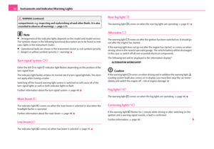 23
23 24
24 25
25 26
26 27
27 28
28 29
29 30
30 31
31 32
32 33
33 34
34 35
35 36
36 37
37 38
38 39
39 40
40 41
41 42
42 43
43 44
44 45
45 46
46 47
47 48
48 49
49 50
50 51
51 52
52 53
53 54
54 55
55 56
56 57
57 58
58 59
59 60
60 61
61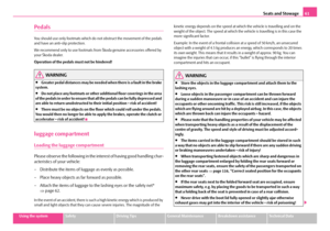 62
62 63
63 64
64 65
65 66
66 67
67 68
68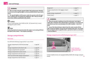 69
69 70
70 71
71 72
72 73
73 74
74 75
75 76
76 77
77 78
78 79
79 80
80 81
81 82
82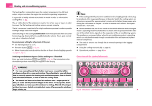 83
83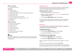 84
84 85
85 86
86 87
87 88
88 89
89 90
90 91
91 92
92 93
93 94
94 95
95 96
96 97
97 98
98 99
99 100
100 101
101 102
102 103
103 104
104 105
105 106
106 107
107 108
108 109
109 110
110 111
111 112
112 113
113 114
114 115
115 116
116 117
117 118
118 119
119 120
120 121
121 122
122 123
123 124
124 125
125 126
126 127
127 128
128 129
129 130
130 131
131 132
132 133
133 134
134 135
135 136
136 137
137 138
138 139
139 140
140 141
141 142
142 143
143 144
144 145
145 146
146 147
147 148
148 149
149 150
150 151
151 152
152 153
153 154
154 155
155 156
156 157
157 158
158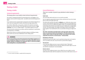 159
159 160
160 161
161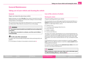 162
162 163
163 164
164 165
165 166
166 167
167 168
168 169
169 170
170 171
171 172
172 173
173 174
174 175
175 176
176 177
177 178
178 179
179 180
180 181
181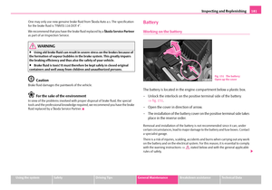 182
182 183
183 184
184 185
185 186
186 187
187 188
188 189
189 190
190 191
191 192
192 193
193 194
194 195
195 196
196 197
197 198
198 199
199 200
200 201
201 202
202 203
203 204
204 205
205 206
206 207
207 208
208 209
209 210
210 211
211 212
212 213
213 214
214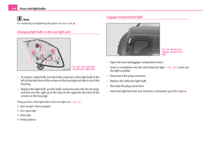 215
215 216
216 217
217 218
218 219
219 220
220 221
221 222
222 223
223 224
224 225
225 226
226 227
227 228
228 229
229 230
230 231
231 232
232 233
233 234
234 235
235 236
236 237
237 238
238 239
239 240
240 241
241