2007 NISSAN TIIDA air duct removal
[x] Cancel search: air duct removalPage 4525 of 5883
PWO-2
< PRECAUTION >
PRECAUTIONS
PRECAUTION
PRECAUTIONS
Precaution for Supplemental Restraint System (SRS) "AIR BAG" and "SEAT BELT
PRE-TENSIONER"
INFOID:0000000001702325
The Supplemental Restraint System such as “AIR BAG” and “SEAT BELT PRE-TENSIONER”, used along
with a front seat belt, helps to reduce the risk or severity of injury to the driver and front passenger for certain
types of collision. Information necessary to service the system safely is included in the SR and SB section of
this Service Manual.
WARNING:
• To avoid rendering the SRS inoperative, which could increase the risk of personal injury or death in
the event of a collision which would result in air bag inflation, all maintenance must be performed by
an authorized NISSAN/INFINITI dealer.
Improper maintenance, including incorrect removal and installation of the SRS, can lead to personal
injury caused by unintentional activation of the system. For removal of Spiral Cable and Air Bag
Module, see the SR section.
Do not use electrical test equipment on any circuit related to the SRS unless instructed to in this
Service Manual. SRS wiring harnesses can be identified by yellow and/or orange harnesses or har-
ness connectors.
Precaution for SRS "AIR BAG" and "SEAT BELT PRE-TENSIONER" Service
INFOID:0000000001702326
Do not use electrical test equipment to check SRS circuits unless instructed to in this Service Manual.
Before servicing the SRS, turn ignition switch OFF, disconnect both battery cables and wait at least 3 min-
utes.
For approximately 3 minutes after the cables are removed, it is still possible for the air bag and seat belt pre-
tensioner to deploy. Therefore, do not work on any SRS connectors or wires until at least 3 minutes have
passed.
The air bag diagnosis sensor unit must always be installed with the arrow mark “⇐” pointing toward the front
of the vehicle for proper operation. Also check air bag diagnosis sensor unit for cracks, deformities or rust
before installation and replace as required.
The spiral cable must be aligned with the neutral position since its rotations are limited. Do not attempt to
turn steering wheel or column after removal of steering gear.
Handle air bag module carefully. Always place driver and front passenger air bag modules with the pad side
facing upward and seat mounted front side air bag module standing with the stud bolt side facing down.
Conduct self-diagnosis to check entire SRS for proper function after replacing any components.
After air bag inflates, the front instrument panel assembly should be replaced if damaged.
Page 4560 of 5883
RF-26
< SYMPTOM DIAGNOSIS >
SQUEAK AND RATTLE TROUBLE DIAGNOSES
The following materials, not available through NISSAN Parts Department, can also be used to repair squeaks
and rattles.
UHMW(TEFLON) TAPE
Insulates where slight movement is present. Ideal for instrument panel applications.
SILICONE GREASE
Used in place of UHMW tape that will be visible or not fit.
Note: Will only last a few months.
SILICONE SPRAY
Use when grease cannot be applied.
DUCT TAPE
Use to eliminate movement.
CONFIRM THE REPAIR
Confirm that the cause of a noise is repaired by test driving the vehicle. Operate the vehicle under the same
conditions as when the noise originally occurred. Refer to the notes on the Diagnostic Worksheet.
Generic Squeak and Rattle TroubleshootingINFOID:0000000001724411
Refer to Table of Contents for specific component removal and installation information.
INSTRUMENT PANEL
Most incidents are caused by contact and movement between:
1. The cluster lid A and instrument panel
2. Acrylic lens and combination meter housing
3. Instrument panel to front pillar garnish
4. Instrument panel to windshield
5. Instrument panel pins
6. Wiring harnesses behind the combination meter
7. A/C defroster duct and duct joint
These incidents can usually be located by tapping or moving the components to duplicate the noise or by
pressing on the components while driving to stop the noise. Most of these incidents can be repaired by apply-
ing felt cloth tape or silicone spray (in hard to reach areas). Urethane pads can be used to insulate wiring har-
ness.
CAUTION:
Do not use silicone spray to isolate a squeak or rattle. If you saturate the area with silicone, you will
not be able to recheck the repair.
CENTER CONSOLE
Components to pay attention to include:
1. Shifter assembly cover to finisher
2. A/C control unit and cluster lid C
3. Wiring harnesses behind audio and A/C control unit
The instrument panel repair and isolation procedures also apply to the center console.
DOORS
Pay attention to the:
1. Finisher and inner panel making a slapping noise
2. Inside handle escutcheon to door finisher
3. Wiring harnesses tapping
4. Door striker out of alignment causing a popping noise on starts and stops
Tapping or moving the components or pressing on them while driving to duplicate the conditions can isolate
many of these incidents. You can usually insulate the areas with felt cloth tape or insulator foam blocks from
the NISSAN Squeak and Rattle Kit (J-43980) to repair the noise.
TRUNK
Trunk noises are often caused by a loose jack or loose items put into the trunk by the owner.
In addition look for:
1. Trunk lid bumpers out of adjustment
Page 4603 of 5883
SQUEAK AND RATTLE TROUBLE DIAGNOSES
SE-7
< SYMPTOM DIAGNOSIS >
C
D
E
F
G
H
I
K
L
MA
B
SE
N
O
P
68370-4B000: 15×25 mm (0.59×0.98 in) pad/68239-13E00: 5 mm (0.20 in) wide tape roll. The following
materials not found in the kit can also be used to repair squeaks and rattles.
UHMW (TEFLON) TAPE
Insulates where slight movement is present. Ideal for instrument panel applications.
SILICONE GREASE
Used instead of UHMW tape that will be visible or not fit.
Note: Will only last a few months.
SILICONE SPRAY
Use when grease cannot be applied.
DUCT TAPE
Use to eliminate movement.
CONFIRM THE REPAIR
Confirm that the cause of a noise is repaired by test driving the vehicle. Operate the vehicle under the same
conditions as when the noise originally occurred. Refer to the notes on the Diagnostic Worksheet.
Generic Squeak and Rattle TroubleshootingINFOID:0000000001710923
Refer to Table of Contents for specific component removal and installation information.
INSTRUMENT PANEL
Most incidents are caused by contact and movement between:
1. The cluster lid A and instrument panel
2. Acrylic lens and combination meter housing
3. Instrument panel to front pillar garnish
4. Instrument panel to windshield
5. Instrument panel mounting pins
6. Wiring harnesses behind the combination meter
7. A/C defroster duct and duct joint
These incidents can usually be located by tapping or moving the components to duplicate the noise or by
pressing on the components while driving to stop the noise. Most of these incidents can be repaired by apply-
ing felt cloth tape or silicone spray (in hard to reach areas). Urethane pads can be used to insulate wiring har-
ness.
CAUTION:
Do not use silicone spray to isolate a squeak or rattle. If you saturate the area with silicone, you will
not be able to recheck the repair.
CENTER CONSOLE
Components to pay attention to include:
1. Shifter assembly cover to finisher
2. A/C control unit and cluster lid C
3. Wiring harnesses behind audio and A/C control unit
The instrument panel repair and isolation procedures also apply to the center console.
DOORS
Pay attention to the:
1. Finisher and inner panel making a slapping noise
2. Inside handle escutcheon to door finisher
3. Wiring harnesses tapping
4. Door striker out of alignment causing a popping noise on starts and stops
Tapping or moving the components or pressing on them while driving to duplicate the conditions can isolate
many of these incidents. You can usually insulate the areas with felt cloth tape or insulator foam blocks from
the NISSAN Squeak and Rattle Kit (J-43980) to repair the noise.
TRUNK
Trunk noises are often caused by a loose jack or loose items put into the trunk by the owner.
In addition look for:
1. Trunk lid bumpers out of adjustment
Page 4745 of 5883
SR-2
< PRECAUTION >
PRECAUTIONS
PRECAUTION
PRECAUTIONS
Precaution for Supplemental Restraint System (SRS) "AIR BAG" and "SEAT BELT
PRE-TENSIONER"
INFOID:0000000001404297
The Supplemental Restraint System such as “AIR BAG” and “SEAT BELT PRE-TENSIONER”, used along
with a front seat belt, helps to reduce the risk or severity of injury to the driver and front passenger for certain
types of collision. Information necessary to service the system safely is included in the SR and SB section of
this Service Manual.
WARNING:
• To avoid rendering the SRS inoperative, which could increase the risk of personal injury or death in
the event of a collision which would result in air bag inflation, all maintenance must be performed by
an authorized NISSAN/INFINITI dealer.
Improper maintenance, including incorrect removal and installation of the SRS, can lead to personal
injury caused by unintentional activation of the system. For removal of Spiral Cable and Air Bag
Module, see the SR section.
Do not use electrical test equipment on any circuit related to the SRS unless instructed to in this
Service Manual. SRS wiring harnesses can be identified by yellow and/or orange harnesses or har-
ness connectors.
Precaution for SRS "AIR BAG" and "SEAT BELT PRE-TENSIONER" Service
INFOID:0000000001404298
Do not use electrical test equipment to check SRS circuits unless instructed to in this Service Manual.
Before servicing the SRS, turn ignition switch OFF, disconnect both battery cables and wait at least 3 min-
utes.
For approximately 3 minutes after the cables are removed, it is still possible for the air bag and seat belt pre-
tensioner to deploy. Therefore, do not work on any SRS connectors or wires until at least 3 minutes have
passed.
The air bag diagnosis sensor unit must always be installed with the arrow mark “⇐” pointing toward the front
of the vehicle for proper operation. Also check air bag diagnosis sensor unit for cracks, deformities or rust
before installation and replace as required.
The spiral cable must be aligned with the neutral position since its rotations are limited. Do not attempt to
turn steering wheel or column after removal of steering gear.
Handle air bag module carefully. Always place driver and front passenger air bag modules with the pad side
facing upward and seat mounted front side air bag module standing with the stud bolt side facing down.
Conduct self-diagnosis to check entire SRS for proper function after replacing any components.
After air bag inflates, the front instrument panel assembly should be replaced if damaged.
Page 4855 of 5883
SRC-86
< PRECAUTION >
PRECAUTIONS
PRECAUTION
PRECAUTIONS
Precaution for Supplemental Restraint System (SRS) "AIR BAG" and "SEAT BELT
PRE-TENSIONER"
INFOID:0000000001396424
The Supplemental Restraint System such as “AIR BAG” and “SEAT BELT PRE-TENSIONER”, used along
with a front seat belt, helps to reduce the risk or severity of injury to the driver and front passenger for certain
types of collision. Information necessary to service the system safely is included in the SR and SB section of
this Service Manual.
WARNING:
To avoid rendering the SRS inoperative, which could increase the risk of personal injury or death in
the event of a collision which would result in air bag inflation, all maintenance must be performed by
an authorized NISSAN/INFINITI dealer.
Improper maintenance, including incorrect removal and installation of the SRS, can lead to personal
injury caused by unintentional activation of the system. For removal of Spiral Cable and Air Bag
Module, see the SR section.
Do not use electrical test equipment on any circuit related to the SRS unless instructed to in this
Service Manual. SRS wiring harnesses can be identified by yellow and/or orange harnesses or har-
ness connectors.
Precaution for SRS "AIR BAG" and "SEAT BELT PRE-TENSIONER" Service
INFOID:0000000001396425
Do not use electrical test equipment to check SRS circuits unless instructed to in this Service Manual.
Before servicing the SRS, turn ignition switch OFF, disconnect both battery cables and wait at least 3 min-
utes.
For approximately 3 minutes after the cables are removed, it is still possible for the air bag and seat belt pre-
tensioner to deploy. Therefore, do not work on any SRS connectors or wires until at least 3 minutes have
passed.
The air bag diagnosis sensor unit must always be installed with the arrow mark “⇐” pointing toward the front
of the vehicle for proper operation. Also check air bag diagnosis sensor unit for cracks, deformities or rust
before installation and replace as required.
The spiral cable must be aligned with the neutral position since its rotations are limited. Do not attempt to
turn steering wheel or column after removal of steering gear.
Handle air bag module carefully. Always place driver and front passenger air bag modules with the pad side
facing upward and seat mounted front side air bag module standing with the stud bolt side facing down.
Conduct self-diagnosis to check entire SRS for proper function after replacing any components.
After air bag inflates, the front instrument panel assembly should be replaced if damaged.
Page 4864 of 5883
STEERING COLUMN
ST-9
< ON-VEHICLE REPAIR >
C
D
E
F
H
I
J
K
L
MA
B
ST
N
O
P
STEERING COLUMN
Removal and InstallationINFOID:0000000001282500
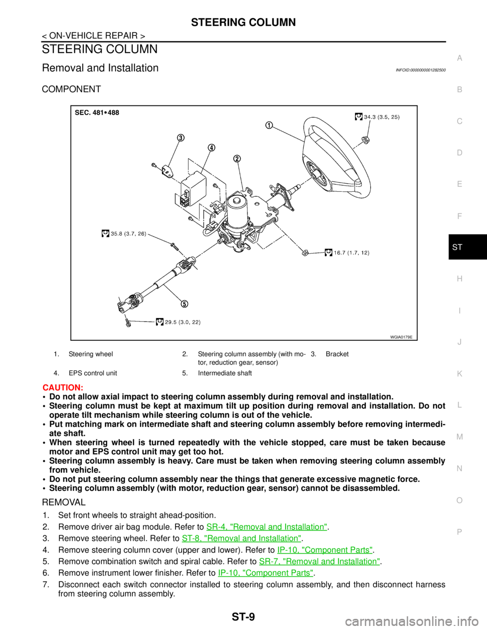
COMPONENT
CAUTION:
Do not allow axial impact to steering column assembly during removal and installation.
Steering column must be kept at maximum tilt up position during removal and installation. Do not
operate tilt mechanism while steering column is out of the vehicle.
Put matching mark on intermediate shaft and steering column assembly before removing intermedi-
ate shaft.
When steering wheel is turned repeatedly with the vehicle stopped, care must be taken because
motor and EPS control unit may get too hot.
Steering column assembly is heavy. Care must be taken when removing steering column assembly
from vehicle.
Do not put steering column assembly near the things that generate excessive magnetic force.
Steering column assembly (with motor, reduction gear, sensor) cannot be disassembled.
REMOVAL
1. Set front wheels to straight ahead-position.
2. Remove driver air bag module. Refer to SR-4, "
Removal and Installation".
3. Remove steering wheel. Refer to ST-8, "
Removal and Installation".
4. Remove steering column cover (upper and lower). Refer to IP-10, "
Component Parts".
5. Remove combination switch and spiral cable. Refer to SR-7, "
Removal and Installation".
6. Remove instrument lower finisher. Refer to IP-10, "
Component Parts".
7. Disconnect each switch connector installed to steering column assembly, and then disconnect harness
from steering column assembly.
1. Steering wheel 2. Steering column assembly (with mo-
tor, reduction gear, sensor)3. Bracket
4. EPS control unit 5. Intermediate shaft
WGIA0179E
Page 4865 of 5883
ST-10
< ON-VEHICLE REPAIR >
STEERING COLUMN
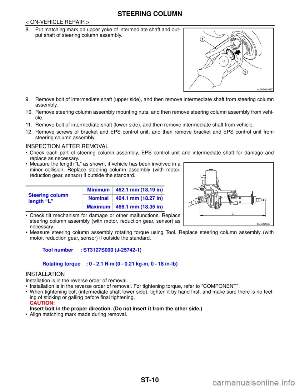
8. Put matching mark on upper yoke of intermediate shaft and out-
put shaft of steering column assembly.
9. Remove bolt of intermediate shaft (upper side), and then remove intermediate shaft from steering column
assembly.
10. Remove steering column assembly mounting nuts, and then remove steering column assembly from vehi-
cle.
11. Remove bolt of intermediate shaft (lower side), and then remove intermediate shaft from vehicle.
12. Remove screws of bracket and EPS control unit, and then remove bracket and EPS control unit from
steering column assembly.
INSPECTION AFTER REMOVAL
Check each part of steering column assembly, EPS control unit and intermediate shaft for damage and
replace as necessary.
Measure the length “L” as shown, if vehicle has been involved in a
minor collision. Replace steering column assembly (with motor,
reduction gear, sensor) if outside the standard.
Check tilt mechanism for damage or other malfunctions. Replace
steering column assembly (with motor, reduction gear, sensor) as
necessary.
Measure steering column assembly rotating torque using Tool. Replace steering column assembly (with
motor, reduction gear, sensor) if outside the standard.
INSTALLATION
Installation is in the reverse order of removal.
Installation is in the reverse order of removal. For tightening torque, refer to "COMPONENT".
When tightening bolt (intermediate shaft lower side), tighten it by hand first, and make sure there is no feel-
ing of sticking or galling before final tightening.
CAUTION:
Insert bolt in the proper direction. (Do not insert it from the other side.)
Align matching mark made during removal.
ALGIA0019ZZ
Steering column
length “L”Minimum 462.1 mm (18.19 in)
Nominal 464.1 mm (18.27 in)
Maximum 466.1 mm (18.35 in)
Tool number : ST3127S000 (J-25742-1)
Rotating torque : 0 - 2.1 N·m (0 - 0.21 kg-m, 0 - 18 in-lb)
SGIA1293E
Page 4950 of 5883

TM-4
Vehicle Speed When Performing and Releasing
Complete Lock-up .................................................
188
ON-VEHICLE REPAIR ...............................189
TRANSMISSION CONTROL MODULE ..........189
Exploded View .......................................................189
Removal and Installation .......................................189
CONTROL SYSTEM ........................................191
Control Valve Assembly and Accumulators ...........191
PARK/NEUTRAL POSITION (PNP) SWITCH .195
Park/Neutral Position (PNP) Switch ......................195
REVOLUTION SENSOR ..................................197
Revolution Sensor .................................................197
Turbine Revolution Sensor (Power Train Revolu-
tion Sensor) ...........................................................
197
DIFFERENTIAL SIDE OIL SEAL ....................199
Differential Side Oil Seal ........................................199
SHIFT CONTROL SYSTEM ............................200
Control Device Removal and Installation ...............200
Control Device Disassembly and Assembly ..........203
Selector Lever Knob Removal and Installation ......203
Adjustment of A/T Position ....................................204
Checking of A/T Position .......................................204
KEY INTERLOCK CABLE ...............................206
Removal and Installation .......................................206
AIR BREATHER HOSE ...................................209
Removal and Installation .......................................209
REMOVAL AND INSTALLATION ..............210
TRANSAXLE ASSEMBLY ..............................210
Exploded View .......................................................210
Removal and Installation .......................................210
DISASSEMBLY AND ASSEMBLY ............213
OVERHAUL .....................................................213
Component ............................................................213
Oil Channel ............................................................219
Location of Adjusting Shims, Needle Bearings and
Thrust Washers .....................................................
220
Location of Snap Rings .........................................221
DISASSEMBLY ...............................................222
Disassembly ..........................................................222
REPAIR FOR COMPONENT PARTS ..............237
Manual Shaft .........................................................237
Oil Pump ................................................................240
Control Valve Assembly ........................................243
Control Valve Upper Body .....................................252
Control Valve Lower Body .....................................255
Reverse Clutch ......................................................258
High Clutch ............................................................262
Forward and Overrun Clutches .............................267
Low & Reverse Brake ...........................................273
Rear Internal Gear and Forward Clutch Hub ........278
Output Shaft, Output Gear, Idler Gear, Reduction
Pinion Gear and Bearing Retainer ........................
281
Band Servo Piston Assembly ................................287
Final Drive .............................................................292
ASSEMBLY ......................................................297
Assembly (1) .........................................................297
Adjustment (1) .......................................................298
Assembly (2) .........................................................303
Adjustment (2) .......................................................307
Assembly (3) .........................................................311
SERVICE DATA AND SPECIFICATIONS
(SDS) .........................................................
319
SERVICE DATA AND SPECIFICATIONS
(SDS) ................................................................
319
General Specification ............................................319
Vehicle Speed at Which Gear Shifting Occurs .....319
Vehicle Speed at When Lock-up Occurs/Releases
.
319
Stall Speed ............................................................319
Line Pressure ........................................................319
Adjusting shims, Needle Bearings, Thrust Wash-
ers and Snap Rings ..............................................
320
Control Valves .......................................................321
Accumulator ..........................................................321
Clutches and Brakes .............................................321
Final Drive .............................................................323
Planetary Carrier ...................................................323
Oil Pump ...............................................................323
Input Shaft .............................................................323
Reduction Pinion Gear ..........................................323
Band Servo ...........................................................323
Output Shaft ..........................................................323
Bearing Retainer ...................................................324
Total End Play .......................................................324
Reverse Clutch End Play ......................................324
Removal and Installation .......................................324
Shift Solenoid Valves ............................................324
Solenoid Valves ....................................................324
A/T Fluid Temperature Sensor ..............................325
Revolution Sensor .................................................325
Dropping Resistor .................................................325
Turbine Revolution Sensor (Power Train Revolu-
tion Sensor) ...........................................................
325
TYPE 2 (4AT: RE4F03B)
BASIC INSPECTION .................................
326
DIAGNOSIS AND REPAIR WORKFLOW ........326
Work Flow .............................................................326
Diagnostic Work Sheet .........................................327
FUNCTION DIAGNOSIS ...........................329
A/T CONTROL SYSTEM ..................................329