Page 2969 of 5883
![NISSAN TIIDA 2007 Service Repair Manual EM-322
< DISASSEMBLY AND ASSEMBLY >[K9K]
CYLINDER BLOCK
e. Position bearing insert [SST: KV113B0160 (Mot. 1493-01)] on
the bearing cap.
f. Install the main bearing in bearing insert [SST: KV113B0160
( NISSAN TIIDA 2007 Service Repair Manual EM-322
< DISASSEMBLY AND ASSEMBLY >[K9K]
CYLINDER BLOCK
e. Position bearing insert [SST: KV113B0160 (Mot. 1493-01)] on
the bearing cap.
f. Install the main bearing in bearing insert [SST: KV113B0160
(](/manual-img/5/57395/w960_57395-2968.png)
EM-322
< DISASSEMBLY AND ASSEMBLY >[K9K]
CYLINDER BLOCK
e. Position bearing insert [SST: KV113B0160 (Mot. 1493-01)] on
the bearing cap.
f. Install the main bearing in bearing insert [SST: KV113B0160
(Mot. 1493-01)], then press at (A) until the main bearing is
touching at (B) with bearing insert.
g. Lubricate the main bearing with engine oil.
h. Install the crankshaft.
i. Install the lateral shims on bearing No. 3, putting the grooves on
the crankshaft side.
j. Degrease the gasket faces (of the cylinder block and bearing
No. 1). They should be clean, dry and free from grease (in par-
ticular, remove finger marks).
k. Lay two beads of liquid sealant with a width of 4 mm (0.16 in) on
bearing No. 1 of the cylinder block.
l. Install the main bearing caps on bearing cap No. 1 (these are
numbered from 1 - 5 and these numbers should be positioned
opposite the water pump). Then tighten the bolts to a torque of
25 N·m (2.6 kg-m, 18 ft-lb) plus an angle tightening of 47
degrees.
m. Turn all bolts 47 degrees clockwise (angle tightening).
CAUTION:
Check and confirm the tightening angle by using the angle
wrench [SST: KV10112100 ( — )] or protractor. Avoid judg-
ment by visual inspection without the tool.
n. Check the lateral play. Refer to EM-330, "
Inspection".
9. Install connecting rod bearing with the following procedure.
MBIB0474E
MBIB0475E
MBIB0478E
: 25.0 N·m (2.6 kg-m, 18 ft-lb)
MBIB0476E
Page 2973 of 5883
![NISSAN TIIDA 2007 Service Repair Manual EM-326
< DISASSEMBLY AND ASSEMBLY >[K9K]
CYLINDER BLOCK
e. Ensure the break in each piston ring is correctly oriented as
shown.
f. Apply new engine oil to the pistons.
g. Install the connecting rod/pi NISSAN TIIDA 2007 Service Repair Manual EM-326
< DISASSEMBLY AND ASSEMBLY >[K9K]
CYLINDER BLOCK
e. Ensure the break in each piston ring is correctly oriented as
shown.
f. Apply new engine oil to the pistons.
g. Install the connecting rod/pi](/manual-img/5/57395/w960_57395-2972.png)
EM-326
< DISASSEMBLY AND ASSEMBLY >[K9K]
CYLINDER BLOCK
e. Ensure the break in each piston ring is correctly oriented as
shown.
f. Apply new engine oil to the pistons.
g. Install the connecting rod/piston assemblies into the cylinder
block using the ring, being careful to fit them the right way round
(mark towards the flywheel).
h. Install the connecting rods onto the oiled crankshaft pins of the
crankshaft.
i. Install the connecting rod caps, ensuring they are correctly
matched.
j. Tighten the connecting rod cap bolts.
k. Turn all bolts 45 degrees clockwise (angle tightening).
CAUTION:
Check and confirm the tightening angle by using the angle wrench [SST: KV10112100 ( — )] or pro-
tractor. Avoid judgment by visual inspection without the tool.
l. Inspect that the big end lateral play. Refer to EM-330, "
Inspection".
11. Install the oil pump sprocket and chain.
12. Tighten oil pump mounting bolts.
13. Install water pump, Refer to CO-66, "
Removal and Installation".
NOTE:
The gasket faces (cylinder block, crankshaft cover and water
pump) must be clean, dry and free from grease (in particular,
remove finger marks).
14. Install crankshaft cover oil seal with a new one.
15. Install the crankshaft cover in the numerical order as shown.
16. Apply two beads (B) of liquid gasket, with a diameter of 5 mm
(0.20 in).
Apply two points (C) of liquid gasket, with a diameter of 5 mm
(0.20 in) at the intersection of the crankshaft cover and the cylin-
der block.
Use Genuine Liquid Gasket or equivalent.: 20.0 N·m (2.0 kg-m, 15 ft-lb)
: 25.0 N·m (2.6 kg-m, 18 ft-lb)
: 11.0 N·m (1.1 kg-m, 8 ft-lb)
MBIB0339E
MBIB0442E
E1BIA0051ZZ
MBIB0483E
Page 2977 of 5883
![NISSAN TIIDA 2007 Service Repair Manual EM-330
< DISASSEMBLY AND ASSEMBLY >[K9K]
CYLINDER BLOCK
31. Remove the nut, the cover, the protector and the threaded rod.
32. Install ring gear stopper [SST: KV113B0060 (Mot. 582-01)] and
tighten fly NISSAN TIIDA 2007 Service Repair Manual EM-330
< DISASSEMBLY AND ASSEMBLY >[K9K]
CYLINDER BLOCK
31. Remove the nut, the cover, the protector and the threaded rod.
32. Install ring gear stopper [SST: KV113B0060 (Mot. 582-01)] and
tighten fly](/manual-img/5/57395/w960_57395-2976.png)
EM-330
< DISASSEMBLY AND ASSEMBLY >[K9K]
CYLINDER BLOCK
31. Remove the nut, the cover, the protector and the threaded rod.
32. Install ring gear stopper [SST: KV113B0060 (Mot. 582-01)] and
tighten flywheel bolts with new one.
33. Turn all bolts 36 degrees clockwise (angle tightening).
CAUTION:
Check and confirm the tightening angle by using the angle
wrench [SST: KV10112100 ( — )] or protractor. Avoid judg-
ment by visual inspection without the tool.
34. Install the clutch housing. Refer to TM-680, "
Exploded View".
35. Remove ring gear stopper [SST: KV113B0060 (Mot. 582-01)].
InspectionINFOID:0000000001381515
CYLINDER BLOCK TOP SURFACE DISTORTION
Using a scraper, remove gasket on the cylinder block surface, and also remove engine oil, scale, carbon, or
other contamination.
CAUTION:
Be careful not to allow gasket flakes to enter engine oil or engine coolant passages.
Measure the distortion on the cylinder block upper face at some
different points in six directions with a straight edge (A) and feeler
gauge (B).
If it exceeds the limit, replace cylinder block.
PISTON PROTRUSION
1. Clean the piston head.
2. Turn the crankshaft one turn in its operating direction to bring piston No. 1 close to TDC.
3. Install dial gauge stand set [KV113B0050 (Mot. 252-01) (com-
mercial service tool) or equivalent tool] on the piston.
4. Install dial gauge stand set [KV113B0040 (Mot. 251-01) (com-
mercial service tool) or equivalent tool] equipped with a gauge
on dial gauge stand set [KV113B0050 (Mot. 252-01) (commer-
cial service tool) or equivalent tool], and find TDC.
NOTE:
All measurements must be carried out along the longitudinal
axis of the engine, in order to eliminate any errors due to tilting
of the piston.
WARNING:
MBIB0499E
: 20.0 N·m (2.0 kg-m, 15 ft-lb)
MBIB0500E
Limit : Refer to EM-337, "CylinderBlock".
PBIC3250J
MBIB0480E
Page 3085 of 5883

EXL-84
< ON-VEHICLE REPAIR >
HEADLAMP
ON-VEHICLE REPAIR
HEADLAMP
Bulb ReplacementINFOID:0000000001529252
HEADLAMP - HALOGEN (HIGH/LOW)
CAUTION:
After installing the halogen bulb, install the back cover and bulb socket securely to ensure a water
tight seal.
1. Turn lighting switch OFF.
2. Disconnect the battery negative terminal.
3. Remove the back cover.
4. Unlock the retaining spring and remove the bulb from the combination lamp.
HEADLAMP - XENON (HIGH/LOW)
CAUTION:
After installing the xenon bulb, install the plastic cap and bulb socket securely to ensure a water tight
seal.
1. Turn lighting switch OFF.
2. Disconnect the battery negative terminal.
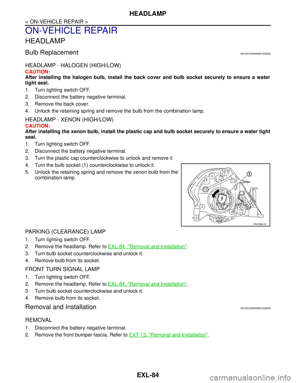
3. Turn the plastic cap counterclockwise to unlock and remove it
4. Turn the bulb socket (1) counterclockwise to unlock it.
5. Unlock the retaining spring and remove the xenon bulb from the
combination lamp.
PARKING (CLEARANCE) LAMP
1. Turn lighting switch OFF.
2. Remove the headlamp. Refer to EXL-84, "
Removal and Installation".
3. Turn bulb socket counterclockwise and unlock it.
4. Remove bulb from its socket.
FRONT TURN SIGNAL LAMP
1. Turn lighting switch OFF.
2. Remove the headlamp. Refer to EXL-84, "
Removal and Installation".
3. Turn bulb socket counterclockwise and unlock it.
4. Remove bulb from its socket.
Removal and InstallationINFOID:0000000001529253
REMOVAL
1. Disconnect the battery negative terminal.
2. Remove the front bumper fascia. Refer to EXT-13, "
Removal and Installation".
PKIC0941E
Page 3086 of 5883

HEADLAMP
EXL-85
< ON-VEHICLE REPAIR >
C
D
E
F
G
H
I
J
K
MA
B
EXL
N
O
P
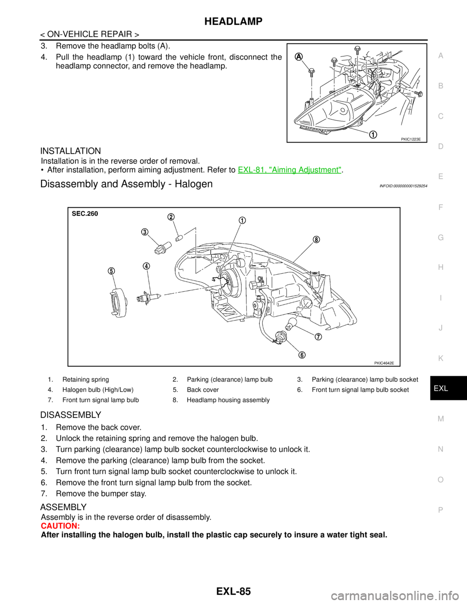
3. Remove the headlamp bolts (A).
4. Pull the headlamp (1) toward the vehicle front, disconnect the
headlamp connector, and remove the headlamp.
INSTALLATION
Installation is in the reverse order of removal.
After installation, perform aiming adjustment. Refer to EXL-81, "
Aiming Adjustment".
Disassembly and Assembly - HalogenINFOID:0000000001529254
DISASSEMBLY
1. Remove the back cover.
2. Unlock the retaining spring and remove the halogen bulb.
3. Turn parking (clearance) lamp bulb socket counterclockwise to unlock it.
4. Remove the parking (clearance) lamp bulb from the socket.
5. Turn front turn signal lamp bulb socket counterclockwise to unlock it.
6. Remove the front turn signal lamp bulb from the socket.
7. Remove the bumper stay.
ASSEMBLY
Assembly is in the reverse order of disassembly.
CAUTION:
After installing the halogen bulb, install the plastic cap securely to insure a water tight seal.
PKIC1223E
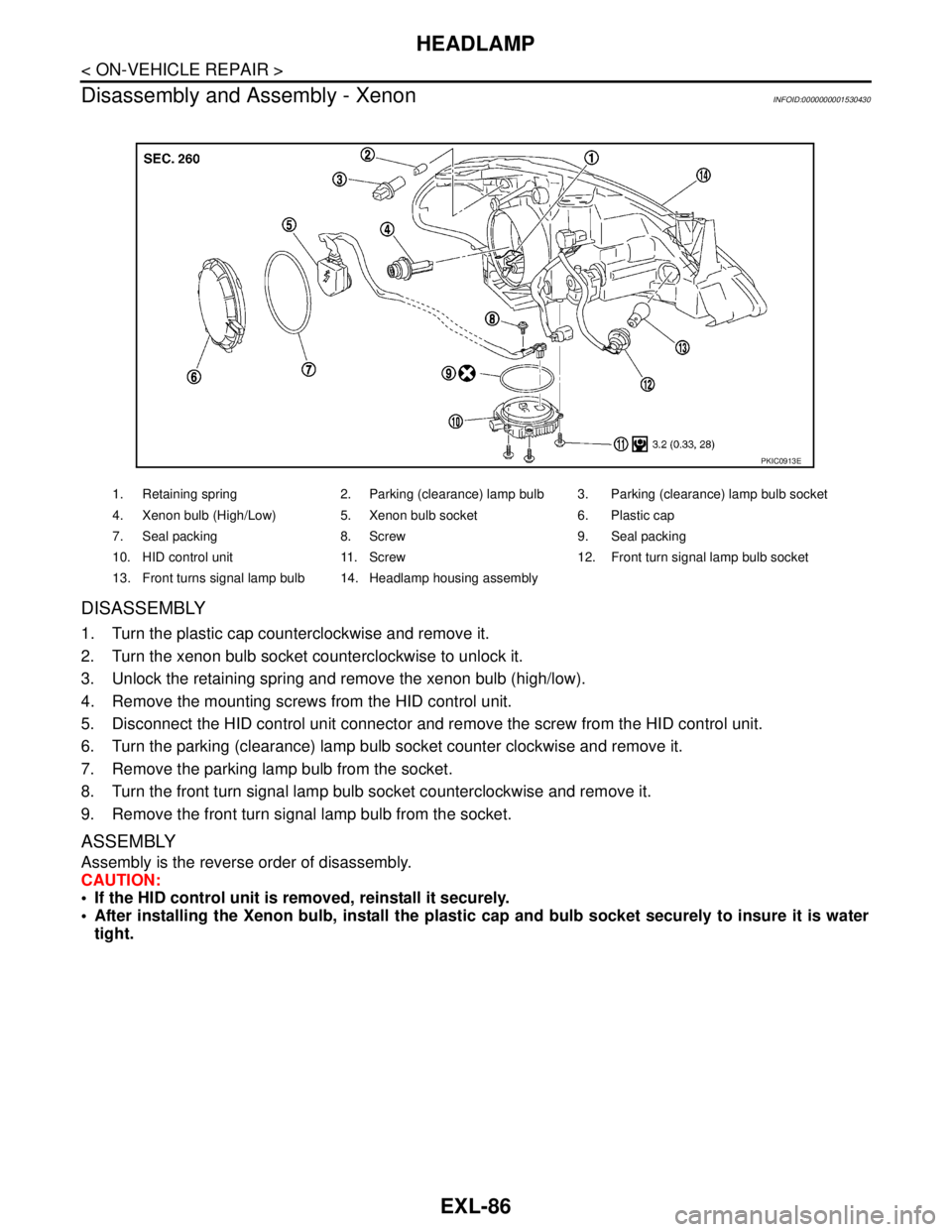
1. Retaining spring 2. Parking (clearance) lamp bulb 3. Parking (clearance) lamp bulb socket
4. Halogen bulb (High/Low) 5. Back cover 6. Front turn signal lamp bulb socket
7. Front turn signal lamp bulb 8. Headlamp housing assembly
PKIC4642E
Page 3087 of 5883

EXL-86
< ON-VEHICLE REPAIR >
HEADLAMP
Disassembly and Assembly - Xenon
INFOID:0000000001530430
DISASSEMBLY
1. Turn the plastic cap counterclockwise and remove it.
2. Turn the xenon bulb socket counterclockwise to unlock it.
3. Unlock the retaining spring and remove the xenon bulb (high/low).
4. Remove the mounting screws from the HID control unit.
5. Disconnect the HID control unit connector and remove the screw from the HID control unit.
6. Turn the parking (clearance) lamp bulb socket counter clockwise and remove it.
7. Remove the parking lamp bulb from the socket.
8. Turn the front turn signal lamp bulb socket counterclockwise and remove it.
9. Remove the front turn signal lamp bulb from the socket.
ASSEMBLY
Assembly is the reverse order of disassembly.
CAUTION:
If the HID control unit is removed, reinstall it securely.
After installing the Xenon bulb, install the plastic cap and bulb socket securely to insure it is water
tight.
1. Retaining spring 2. Parking (clearance) lamp bulb 3. Parking (clearance) lamp bulb socket
4. Xenon bulb (High/Low) 5. Xenon bulb socket 6. Plastic cap
7. Seal packing 8. Screw 9. Seal packing
10. HID control unit 11. Screw 12. Front turn signal lamp bulb socket
13. Front turns signal lamp bulb 14. Headlamp housing assembly
PKIC0913E
Page 3088 of 5883
FRONT FOG LAMP
EXL-87
< ON-VEHICLE REPAIR >
C
D
E
F
G
H
I
J
K
MA
B
EXL
N
O
P
FRONT FOG LAMP
Bulb ReplacementINFOID:0000000001529284
1. Turn the lighting switch OFF.
2. Reposition the fender protector (front) out of the way to access the front fog lamp.
3. Disconnect the front fog lamp connector (1).
4. Turn the bulb socket (2) counterclockwise to unlock it.
5. Remove the socket and bulb from the fog lamp.
6. Remove the bulb from the socket.
Removal and InstallationINFOID:0000000001529285
REMOVAL
1. Reposition the fender protector (front) out of the way to access the front fog lamp.
2. Disconnect the front fog lamp connector.
3. Release the pawl and remove the front bumper finisher from the front bumper.
4. Remove front fog lamp bolt and remove the front fog lamp from the front bumper finisher.
INSTALLATION
Installation is in the reverse order of removal.
PKIC1071E
1. Front fog lamp 2. Front bumper finisher 3. Front fog lamp bolt
WKIA5420E
Page 3093 of 5883
EXL-92
< ON-VEHICLE REPAIR >
SIDE TURN SIGNAL LAMP
SIDE TURN SIGNAL LAMP
Bulb ReplacementINFOID:0000000001530538
1. Remove the side turn signal lamp. Refer to EXL-92, "Removal and Installation".
2. Turn bulb socket counterclockwise to unlock it.
3. Remove the bulb from the socket.
Removal and InstallationINFOID:0000000001530539
REMOVAL
1. Insert a suitable tool under the side turn signal lamp. While
pushing in on the side turn signal lamp pawl, pull the lamp away
from the front fender as shown.
2. Disconnect the side turn signal lamp connector and remove the
side turn signal lamp.
NOTE:
Secure the side turn signal lamp harness with tape to prevent
the harness from falling into the front fender.
INSTALLATION
Installation is in the reverse order of removal.
CAUTION:
Install the lamp housing with the bead facing up.
PKIB8657E
PKIB8656E