2007 NISSAN TIIDA clock
[x] Cancel search: clockPage 3094 of 5883
REAR COMBINATION LAMP
EXL-93
< ON-VEHICLE REPAIR >
C
D
E
F
G
H
I
J
K
MA
B
EXL
N
O
P
REAR COMBINATION LAMP
Bulb ReplacementINFOID:0000000001530525
HATCHBACK
1. Remove the rear combination lamp. Refer to EXL-93, "Removal and Installation".
2. Turn the bulb socket counterclockwise to unlock it.
3. Remove the bulb.
4. Installation is in the reverse order of removal.
SEDAN
1. Remove the trunk side finisher. Refer to INT-35, "Removal and Installation".
2. Turn the bulb socket counterclockwise to unlock it.
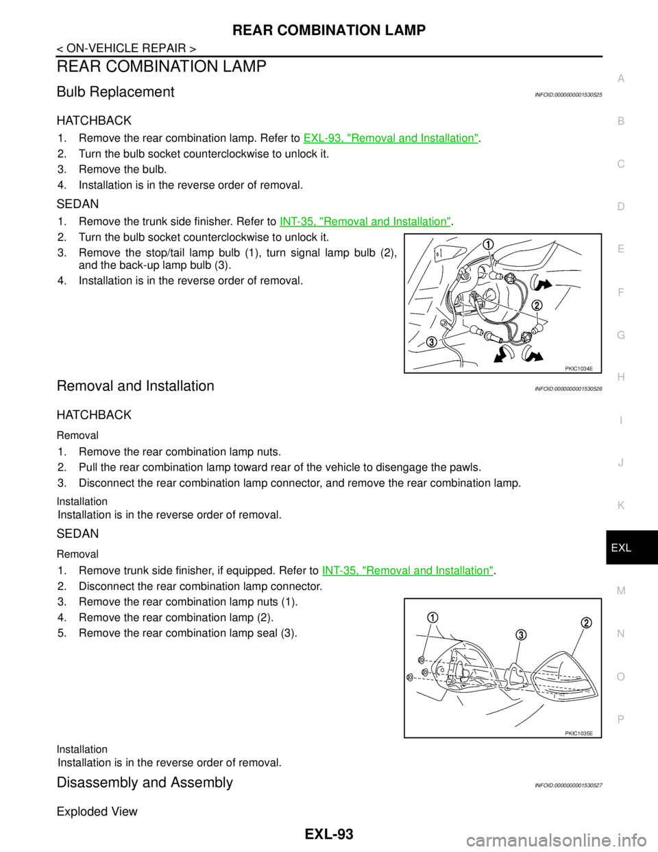
3. Remove the stop/tail lamp bulb (1), turn signal lamp bulb (2),
and the back-up lamp bulb (3).
4. Installation is in the reverse order of removal.
Removal and InstallationINFOID:0000000001530526
HATCHBACK
Removal
1. Remove the rear combination lamp nuts.
2. Pull the rear combination lamp toward rear of the vehicle to disengage the pawls.
3. Disconnect the rear combination lamp connector, and remove the rear combination lamp.
Installation
Installation is in the reverse order of removal.
SEDAN
Removal
1. Remove trunk side finisher, if equipped. Refer to INT-35, "Removal and Installation".
2. Disconnect the rear combination lamp connector.
3. Remove the rear combination lamp nuts (1).
4. Remove the rear combination lamp (2).
5. Remove the rear combination lamp seal (3).
Installation
Installation is in the reverse order of removal.
Disassembly and AssemblyINFOID:0000000001530527
Exploded View
PKIC1034E
PKIC1035E
Page 3099 of 5883
EXL-98
< ON-VEHICLE REPAIR >
LICENSE PLATE LAMP
LICENSE PLATE LAMP
Bulb ReplacementINFOID:0000000001530532
HATCHBACK
1. Remove the license plate lamp. Refer to INT-35, "Removal and Installation".
2. Turn the bulb socket counterclockwise to unlock it.
3. Remove the bulb from the socket.
4. Installation is in the reverse order of removal.
SEDAN
1. Remove the trunk lid finisher. Refer to INT-35, "Removal and Installation".
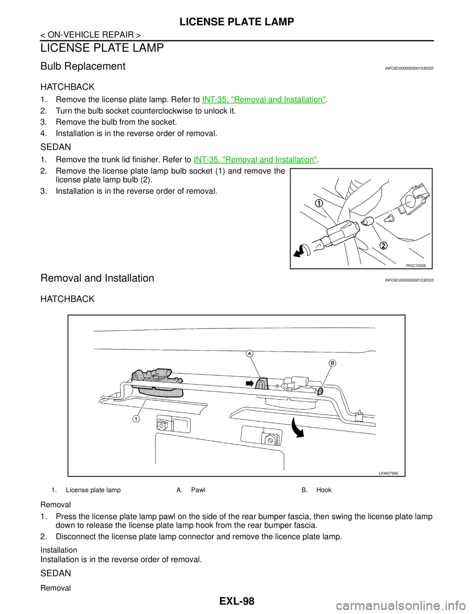
2. Remove the license plate lamp bulb socket (1) and remove the
license plate lamp bulb (2).
3. Installation is in the reverse order of removal.
Removal and InstallationINFOID:0000000001530533
HATCHBACK
Removal
1. Press the license plate lamp pawl on the side of the rear bumper fascia, then swing the license plate lamp
down to release the license plate lamp hook from the rear bumper fascia.
2. Disconnect the license plate lamp connector and remove the licence plate lamp.
Installation
Installation is in the reverse order of removal.
SEDAN
Removal
PKIC1055E
1. License plate lamp A. Pawl B. Hook
LKIA0759E
Page 3101 of 5883
EXL-100
< ON-VEHICLE REPAIR >
REAR FOG LAMP
REAR FOG LAMP
Bulb ReplacementINFOID:0000000001530536
1. Remove the clips for the rear bumper fascia lower side. Refer to EXT-17, "Removal and Installation -
Sedan".
2. Disconnect the rear fog lamp connector.
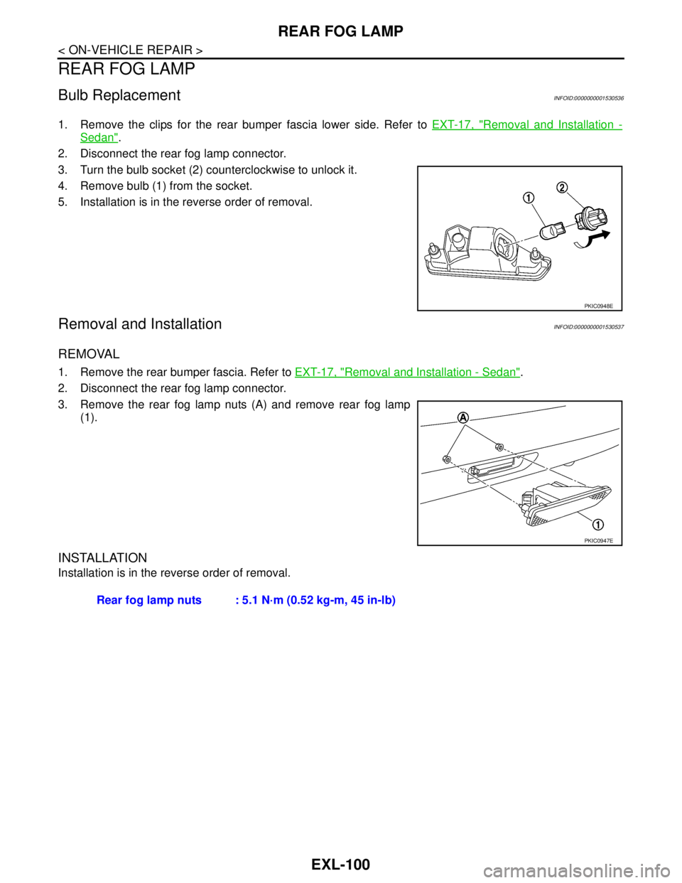
3. Turn the bulb socket (2) counterclockwise to unlock it.
4. Remove bulb (1) from the socket.
5. Installation is in the reverse order of removal.
Removal and InstallationINFOID:0000000001530537
REMOVAL
1. Remove the rear bumper fascia. Refer to EXT-17, "Removal and Installation - Sedan".
2. Disconnect the rear fog lamp connector.
3. Remove the rear fog lamp nuts (A) and remove rear fog lamp
(1).
INSTALLATION
Installation is in the reverse order of removal.
PKIC0948E
PKIC0947E
Rear fog lamp nuts : 5.1 N·m (0.52 kg-m, 45 in-lb)
Page 3108 of 5883
EXT-4
< ON-VEHICLE MAINTENANCE >
SQUEAK AND RATTLE TROUBLE DIAGNOSIS
ON-VEHICLE MAINTENANCE
SQUEAK AND RATTLE TROUBLE DIAGNOSIS
Work FlowINFOID:0000000001568921
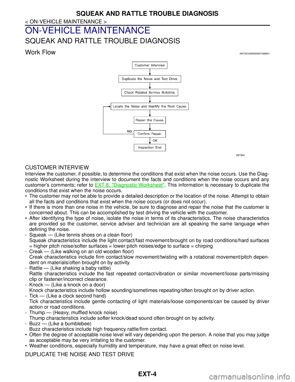
CUSTOMER INTERVIEW
Interview the customer, if possible, to determine the conditions that exist when the noise occurs. Use the Diag-
nostic Worksheet during the interview to document the facts and conditions when the noise occurs and any
customer's comments; refer to EXT-8, "
Diagnostic Worksheet". This information is necessary to duplicate the
conditions that exist when the noise occurs.
The customer may not be able to provide a detailed description or the location of the noise. Attempt to obtain
all the facts and conditions that exist when the noise occurs (or does not occur).
If there is more than one noise in the vehicle, be sure to diagnose and repair the noise that the customer is
concerned about. This can be accomplished by test driving the vehicle with the customer.
After identifying the type of noise, isolate the noise in terms of its characteristics. The noise characteristics
are provided so the customer, service adviser and technician are all speaking the same language when
defining the noise.
- Squeak — (Like tennis shoes on a clean floor)
Squeak characteristics include the light contact/fast movement/brought on by road conditions/hard surfaces
= higher pitch noise/softer surfaces = lower pitch noises/edge to surface = chirping
- Creak — (Like walking on an old wooden floor)
Creak characteristics include firm contact/slow movement/twisting with a rotational movement/pitch depen-
dent on materials/often brought on by activity.
- Rattle — (Like shaking a baby rattle)
Rattle characteristics include the fast repeated contact/vibration or similar movement/loose parts/missing
clip or fastener/incorrect clearance.
- Knock — (Like a knock on a door)
Knock characteristics include hollow sounding/sometimes repeating/often brought on by driver action.
- Tick — (Like a clock second hand)
Tick characteristics include gentle contacting of light materials/loose components/can be caused by driver
action or road conditions.
- Thump — (Heavy, muffled knock noise)
Thump characteristics include softer knock/dead sound often brought on by activity.
- Buzz — (Like a bumblebee)
Buzz characteristics include high frequency rattle/firm contact.
Often the degree of acceptable noise level will vary depending upon the person. A noise that you may judge
as acceptable may be very irritating to the customer.
Weather conditions, especially humidity and temperature, may have a great effect on noise level.
DUPLICATE THE NOISE AND TEST DRIVE
SBT842
Page 3166 of 5883
FL-6
< ON-VEHICLE REPAIR >
FUEL LEVEL SENSOR UNIT, FUEL FILTER AND FUEL PUMP ASSEMBLY
b. Disconnect fuel filler hose from fuel filler tube. Refer to FL-10, "HR16DE, HR18DE".
c. Insert fuel tubing into fuel tank through fuel filler hose to drain fuel from fuel tank.
2. Release the fuel pressure from the fuel lines. Refer to EC-377, "
Inspection" (HR16DE with EURO-OBD),
EC-681, "
Inspection" (HR16DE without EURO-OBD), EC-1035, "Inspection" (MR18DE).
3. Open fuel filler lid.
4. Open fuel door and unscrew the fuel filler cap to release the pressure inside the fuel tank.
5. Remove rear seat bottom. Refer to SE-18, "
Removal and Installation".
6. Turn the four retainers 90° in a clockwise direction and remove the fuel pump inspection hole cover.
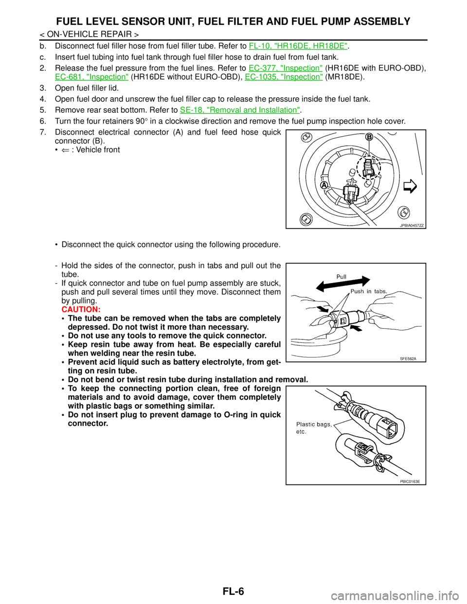
7. Disconnect electrical connector (A) and fuel feed hose quick
connector (B).
⇐ : Vehicle front
Disconnect the quick connector using the following procedure.
- Hold the sides of the connector, push in tabs and pull out the
tube.
- If quick connector and tube on fuel pump assembly are stuck,
push and pull several times until they move. Disconnect them
by pulling.
CAUTION:
The tube can be removed when the tabs are completely
depressed. Do not twist it more than necessary.
Do not use any tools to remove the quick connector.
Keep resin tube away from heat. Be especially careful
when welding near the resin tube.
Prevent acid liquid such as battery electrolyte, from get-
ting on resin tube.
Do not bend or twist resin tube during installation and removal.
To keep the connecting portion clean, free of foreign
materials and to avoid damage, cover them completely
with plastic bags or something similar.
Do not insert plug to prevent damage to O-ring in quick
connector.
JPBIA0457ZZ
SFE562A
PBIC0163E
Page 3168 of 5883
FL-8
< ON-VEHICLE REPAIR >
FUEL LEVEL SENSOR UNIT, FUEL FILTER AND FUEL PUMP ASSEMBLY
Before installing inspection hole cover, confirm that there are no fuel leaks. Refer to "INSPECTION AFTER
INSTALLATION".
1. Install inspection hole cover with the front mark (arrow) facing front of vehicle.
2. Lock clips by turning counterclockwise.
K9KINFOID:0000000001723040
Exploded ViewINFOID:0000000001723041
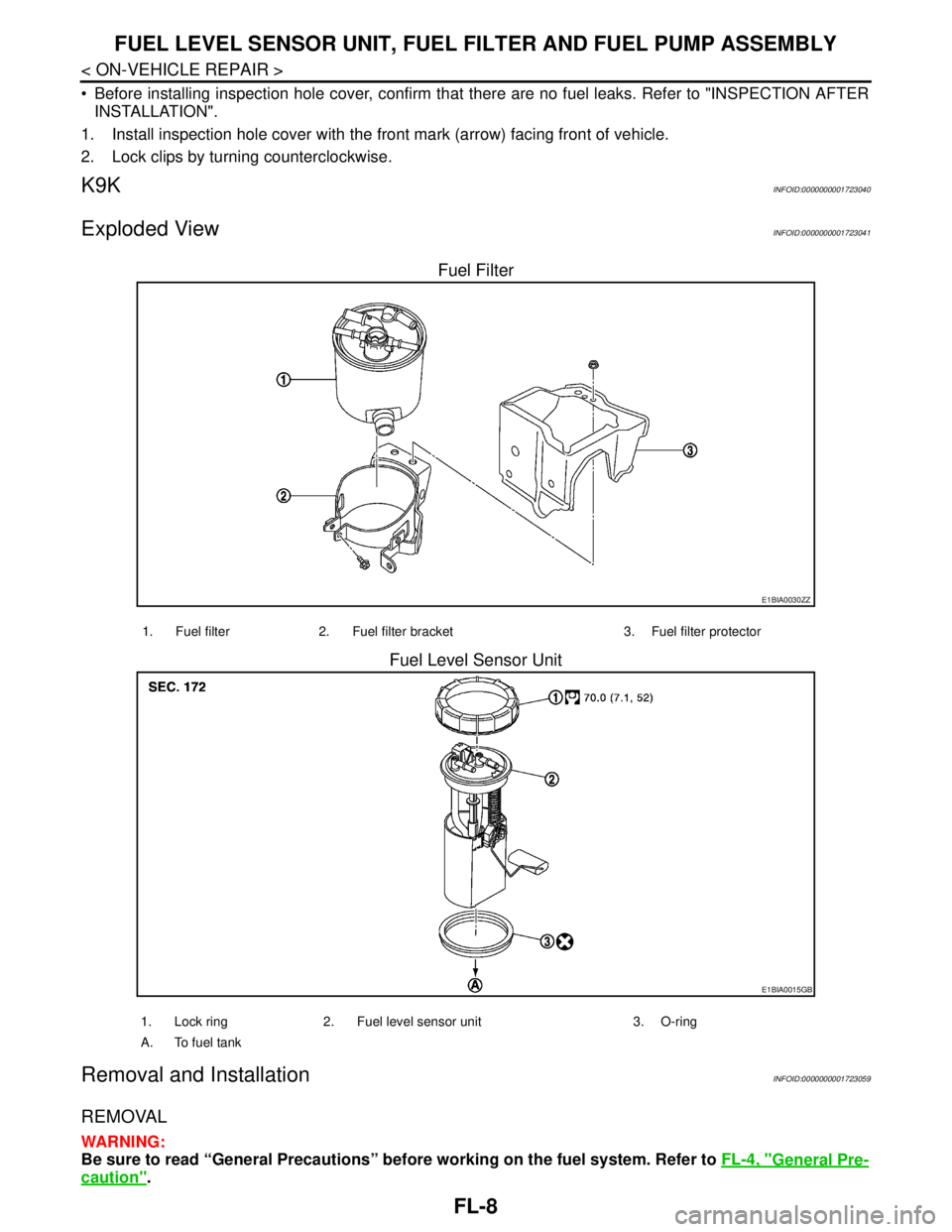
Fuel Filter
Fuel Level Sensor Unit
Removal and InstallationINFOID:0000000001723059
REMOVAL
WARNING:
Be sure to read “General Precautions” before working on the fuel system. Refer to FL-4, "
General Pre-
caution".
E1BIA0030ZZ
1. Fuel filter 2. Fuel filter bracket 3. Fuel filter protector
E1BIA0015GB
1. Lock ring 2. Fuel level sensor unit 3. O-ring
A. To fuel tank
Page 3261 of 5883
GW-2
< SYMPTOM DIAGNOSIS >
SQUEAK AND RATTLE TROUBLE DIAGNOSES
SYMPTOM DIAGNOSIS
SQUEAK AND RATTLE TROUBLE DIAGNOSES
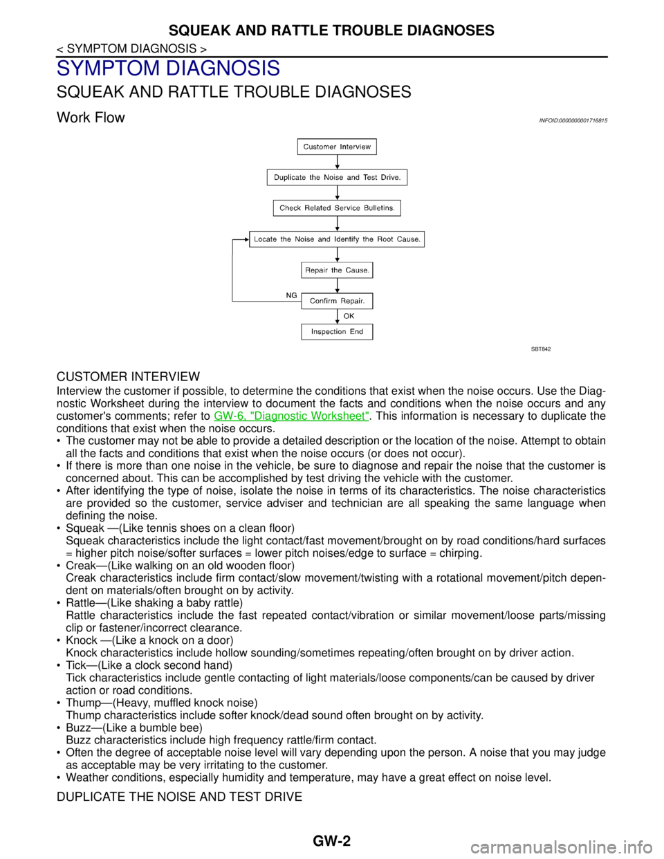
Work FlowINFOID:0000000001716815
CUSTOMER INTERVIEW
Interview the customer if possible, to determine the conditions that exist when the noise occurs. Use the Diag-
nostic Worksheet during the interview to document the facts and conditions when the noise occurs and any
customer's comments; refer to GW-6, "
Diagnostic Worksheet". This information is necessary to duplicate the
conditions that exist when the noise occurs.
• The customer may not be able to provide a detailed description or the location of the noise. Attempt to obtain
all the facts and conditions that exist when the noise occurs (or does not occur).
If there is more than one noise in the vehicle, be sure to diagnose and repair the noise that the customer is
concerned about. This can be accomplished by test driving the vehicle with the customer.
After identifying the type of noise, isolate the noise in terms of its characteristics. The noise characteristics
are provided so the customer, service adviser and technician are all speaking the same language when
defining the noise.
Squeak —(Like tennis shoes on a clean floor)
Squeak characteristics include the light contact/fast movement/brought on by road conditions/hard surfaces
= higher pitch noise/softer surfaces = lower pitch noises/edge to surface = chirping.
Creak—(Like walking on an old wooden floor)
Creak characteristics include firm contact/slow movement/twisting with a rotational movement/pitch depen-
dent on materials/often brought on by activity.
Rattle—(Like shaking a baby rattle)
Rattle characteristics include the fast repeated contact/vibration or similar movement/loose parts/missing
clip or fastener/incorrect clearance.
Knock —(Like a knock on a door)
Knock characteristics include hollow sounding/sometimes repeating/often brought on by driver action.
Tick—(Like a clock second hand)
Tick characteristics include gentle contacting of light materials/loose components/can be caused by driver
action or road conditions.
Thump—(Heavy, muffled knock noise)
Thump characteristics include softer knock/dead sound often brought on by activity.
Buzz—(Like a bumble bee)
Buzz characteristics include high frequency rattle/firm contact.
Often the degree of acceptable noise level will vary depending upon the person. A noise that you may judge
as acceptable may be very irritating to the customer.
Weather conditions, especially humidity and temperature, may have a great effect on noise level.
DUPLICATE THE NOISE AND TEST DRIVE
SBT842
Page 3292 of 5883
HA-10
< PRECAUTION >
PRECAUTIONS
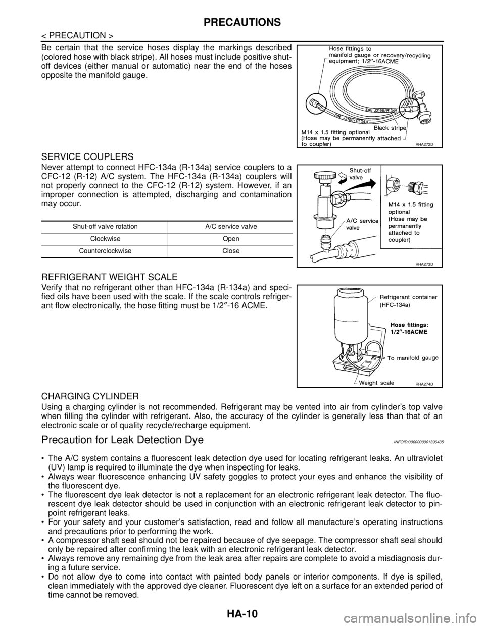
Be certain that the service hoses display the markings described
(colored hose with black stripe). All hoses must include positive shut-
off devices (either manual or automatic) near the end of the hoses
opposite the manifold gauge.
SERVICE COUPLERS
Never attempt to connect HFC-134a (R-134a) service couplers to a
CFC-12 (R-12) A/C system. The HFC-134a (R-134a) couplers will
not properly connect to the CFC-12 (R-12) system. However, if an
improper connection is attempted, discharging and contamination
may occur.
REFRIGERANT WEIGHT SCALE
Verify that no refrigerant other than HFC-134a (R-134a) and speci-
fied oils have been used with the scale. If the scale controls refriger-
ant flow electronically, the hose fitting must be 1/2″-16 ACME.
CHARGING CYLINDER
Using a charging cylinder is not recommended. Refrigerant may be vented into air from cylinder’s top valve
when filling the cylinder with refrigerant. Also, the accuracy of the cylinder is generally less than that of an
electronic scale or of quality recycle/recharge equipment.
Precaution for Leak Detection DyeINFOID:0000000001396435
The A/C system contains a fluorescent leak detection dye used for locating refrigerant leaks. An ultraviolet
(UV) lamp is required to illuminate the dye when inspecting for leaks.
Always wear fluorescence enhancing UV safety goggles to protect your eyes and enhance the visibility of
the fluorescent dye.
The fluorescent dye leak detector is not a replacement for an electronic refrigerant leak detector. The fluo-
rescent dye leak detector should be used in conjunction with an electronic refrigerant leak detector to pin-
point refrigerant leaks.
For your safety and your customer’s satisfaction, read and follow all manufacture’s operating instructions
and precautions prior to performing the work.
A compressor shaft seal should not be repaired because of dye seepage. The compressor shaft seal should
only be repaired after confirming the leak with an electronic refrigerant leak detector.
Always remove any remaining dye from the leak area after repairs are complete to avoid a misdiagnosis dur-
ing a future service.
Do not allow dye to come into contact with painted body panels or interior components. If dye is spilled,
clean immediately with the approved dye cleaner. Fluorescent dye left on a surface for an extended period of
time cannot be removed.
RHA272D
Shut-off valve rotation A/C service valve
Clockwise Open
Counterclockwise Close
RHA273D
RHA274D