2007 NISSAN TIIDA oil
[x] Cancel search: oilPage 3105 of 5883
EXT-1
BODY EXTERIOR, DOORS, ROOF & VEHICLE SECURITY
C
D
E
F
G
H
I
J
L
M
SECTION EXT
A
B
EXT
N
O
P
CONTENTS
EXTERIOR
PRECAUTION ...............................................2
PRECAUTIONS ...................................................2
Precaution for Supplemental Restraint System
(SRS) "AIR BAG" and "SEAT BELT PRE-TEN-
SIONER" ...................................................................
2
Precaution .................................................................2
PREPARATION ............................................3
PREPARATION ...................................................3
Special Service Tool .................................................3
Commercial Service Tool ..........................................3
ON-VEHICLE MAINTENANCE .....................4
SQUEAK AND RATTLE TROUBLE DIAGNO-
SIS .......................................................................
4
Work Flow .................................................................4
Generic Squeak and Rattle Troubleshooting ............6
Diagnostic Worksheet ...............................................8
ON-VEHICLE REPAIR .................................10
CLIP AND FASTENER .......................................10
Description ..............................................................10
FRONT BUMPER ...............................................13
Removal and Installation .........................................13
REAR BUMPER ................................................15
Component ..............................................................15
Removal and Installation - Hatchback .....................15
Removal and Installation - Sedan ............................17
FRONT GRILLE ................................................19
Removal and Installation .........................................19
COWL TOP .......................................................20
Removal and Installation .........................................20
FENDER PROTECTOR ....................................22
Component ..............................................................22
Removal and Installation .........................................22
ROOF SIDE MOLDING .....................................23
Component ..............................................................23
Removal and Installation .........................................23
DOOR OUTSIDE MOLDING .............................25
Component ..............................................................25
Removal and Installation .........................................26
CENTER MUD GUARD .....................................28
Removal and Installation .........................................28
TRUNK LID FINISHER ......................................29
Removal and Installation .........................................29
REAR AIR SPOILER .........................................30
Removal and Installation .........................................30
Page 3106 of 5883
EXT-2
< PRECAUTION >
PRECAUTIONS
PRECAUTION
PRECAUTIONS
Precaution for Supplemental Restraint System (SRS) "AIR BAG" and "SEAT BELT
PRE-TENSIONER"
INFOID:0000000001568917
The Supplemental Restraint System such as “AIR BAG” and “SEAT BELT PRE-TENSIONER”, used along
with a front seat belt, helps to reduce the risk or severity of injury to the driver and front passenger for certain
types of collision. This system includes seat belt switch inputs and dual stage front air bag modules. The SRS
system uses the seat belt switches to determine the front air bag deployment, and may only deploy one front
air bag, depending on the severity of a collision and whether the front occupants are belted or unbelted.
Information necessary to service the system safely is included in the SRS and SB section of this Service Man-
ual.
WARNING:
• To avoid rendering the SRS inoperative, which could increase the risk of personal injury or death in
the event of a collision which would result in air bag inflation, all maintenance must be performed by
an authorized NISSAN/INFINITI dealer.
Improper maintenance, including incorrect removal and installation of the SRS, can lead to personal
injury caused by unintentional activation of the system. For removal of Spiral Cable and Air Bag
Module, see the SRS section.
Do not use electrical test equipment on any circuit related to the SRS unless instructed to in this
Service Manual. SRS wiring harnesses can be identified by yellow and/or orange harnesses or har-
ness connectors.
PrecautionINFOID:0000000001568918
When removing or disassembling any part, be careful not to damage or deform it. Protect parts which may
get in the way with cloth.
When removing parts with a screwdriver or other tool, protect parts by wrapping them with vinyl or tape.
Keep removed parts protected with cloth.
If a clip is deformed or damaged, replace it.
If an unreusable part is removed, replace it with a new one.
Tighten bolts and nuts firmly to the specified torque.
After re-assembly has been completed, make sure each part functions correctly.
Remove stains in the following way.
- Water-soluble stains:
Dip a cloth in warm water, and squeeze tightly. After wiping the stain, wipe with a soft dry cloth.
- Oil stain:
Dissolve a synthetic detergent in warm water (density of 2 to 3% or less), dip the cloth, then clean off the
stain with the cloth. Next, dip the soft cloth in fresh water, and then squeeze it tightly. Then clean off the
detergent completely. Then wipe the area with a soft dry cloth.
Do not use any organic solvent, such as thinner or benzine.
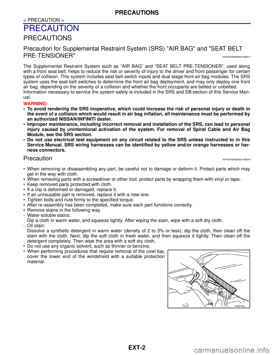
When performing procedures that require removal of the cowl top,
cover the lower end of the windshield with a suitable protection
material.
PIIB3706J
Page 3118 of 5883
EXT-14
< ON-VEHICLE REPAIR >
FRONT BUMPER
CAUTION:
Bumper fascia is made of resin. Do not apply strong force to it, and be careful to prevent contact with
oil.
REMOVAL
1. Open hood.
2. Remove front grille. Refer to EXT-19, "
Removal and Installation".
3. Remove front fender protectors RH/LH. Refer to EXT-22, "
Removal and Installation".
4. Remove engine undercover.
5. Remove screws of front bumper fascia RH/LH.
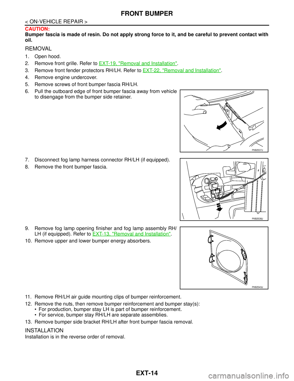
6. Pull the outboard edge of front bumper fascia away from vehicle
to disengage from the bumper side retainer.
7. Disconnect fog lamp harness connector RH/LH (if equipped).
8. Remove the front bumper fascia.
9. Remove fog lamp opening finisher and fog lamp assembly RH/
LH (if equipped). Refer to EXT-13, "
Removal and Installation".
10. Remove upper and lower bumper energy absorbers.
11. Remove RH/LH air guide mounting clips of bumper reinforcement.
12. Remove the nuts, then remove bumper reinforcement and bumper stay(s):
For production, bumper stay LH is part of bumper reinforcement.
For service, bumper stay RH/LH are separate assemblies.
13. Remove bumper side bracket RH/LH after front bumper fascia removal.
INSTALLATION
Installation is in the reverse order of removal.
PIIB2537J
PIIB2538J
PIIB2543J
Page 3134 of 5883
EXT-30
< ON-VEHICLE REPAIR >
REAR AIR SPOILER
REAR AIR SPOILER
Removal and InstallationINFOID:0000000001568939
Removal
1. Disconnect the negative and positive battery cables.
2. Remove back door finisher upper. Refer to INT-35, "
Removal and Installation".
3. Disconnect high mounted stop lamp connector.
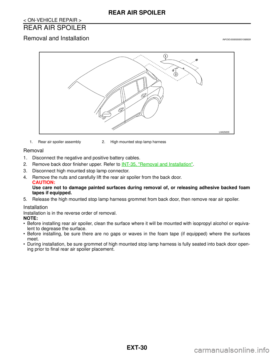
4. Remove the nuts and carefully lift the rear air spoiler from the back door.
CAUTION:
Use care not to damage painted surfaces during removal of, or releasing adhesive backed foam
tapes if equipped.
5. Release the high mounted stop lamp harness grommet from back door, then remove rear air spoiler.
Installation
Installation is in the reverse order of removal.
NOTE:
Before installing rear air spoiler, clean the surface where it will be mounted with isopropyl alcohol or equiva-
lent to degrease the surface.
Before installing, be sure there are no gaps or waves in the foam tape (if equipped) where the surfaces
meet.
During installation, be sure grommet of high mounted stop lamp harness is fully seated into back door open-
ing prior to final rear air spoiler placement.
1. Rear air spoiler assembly 2. High mounted stop lamp harness
LIIA2922E
Page 3137 of 5883
PREPARATION
FAX-3
< PREPARATION >
C
E
F
G
H
I
J
K
L
MA
B
FA X
N
O
P
PREPARATION
PREPARATION
Special Service ToolINFOID:0000000001716782
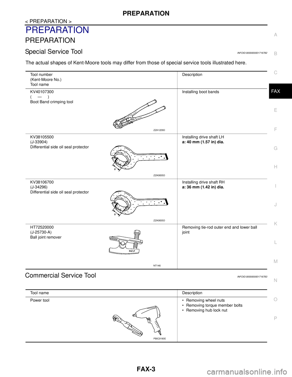
The actual shapes of Kent-Moore tools may differ from those of special service tools illustrated here.
Commercial Service ToolINFOID:0000000001716783
Tool number
(Kent-Moore No.)
Tool nameDescription
KV40107300
(—)
Boot Band crimping toolInstalling boot bands
KV38105500
(J-33904)
Differential side oil seal protectorInstalling drive shaft LH
a: 40 mm (1.57 in) dia.
KV38106700
(J-34296)
Differential side oil seal protectorInstalling drive shaft RH
a: 36 mm (1.42 in) dia.
HT72520000
(J-25730-A)
Ball joint removerRemoving tie-rod outer end and lower ball
joint
ZZA1229D
ZZA0835D
ZZA0835D
NT146
Tool nameDescription
Power tool Removing wheel nuts
Removing torque member bolts
Removing hub lock nut
PBIC0190E
Page 3145 of 5883
FRONT DRIVE SHAFT
FAX-11
< REMOVAL AND INSTALLATION >
C
E
F
G
H
I
J
K
L
MA
B
FA X
N
O
P
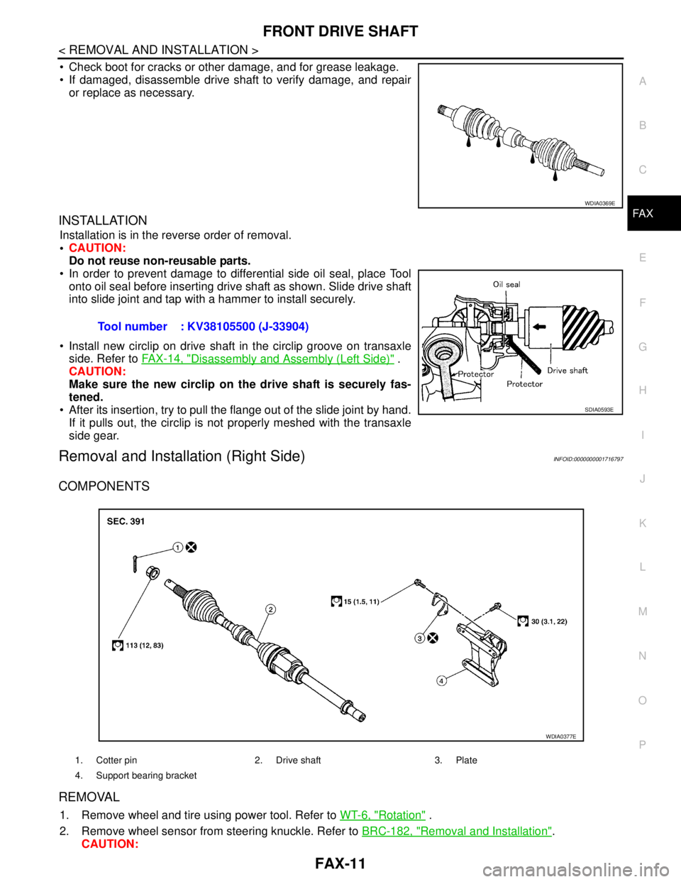
Check boot for cracks or other damage, and for grease leakage.
If damaged, disassemble drive shaft to verify damage, and repair
or replace as necessary.
INSTALLATION
Installation is in the reverse order of removal.
CAUTION:
Do not reuse non-reusable parts.
In order to prevent damage to differential side oil seal, place Tool
onto oil seal before inserting drive shaft as shown. Slide drive shaft
into slide joint and tap with a hammer to install securely.
Install new circlip on drive shaft in the circlip groove on transaxle
side. Refer to FAX-14, "
Disassembly and Assembly (Left Side)" .
CAUTION:
Make sure the new circlip on the drive shaft is securely fas-
tened.
After its insertion, try to pull the flange out of the slide joint by hand.
If it pulls out, the circlip is not properly meshed with the transaxle
side gear.
Removal and Installation (Right Side)INFOID:0000000001716797
COMPONENTS
REMOVAL
1. Remove wheel and tire using power tool. Refer to WT-6, "Rotation" .
2. Remove wheel sensor from steering knuckle. Refer to BRC-182, "
Removal and Installation".
CAUTION:
WDIA0369E
Tool number : KV38105500 (J-33904)
SDIA0593E
1. Cotter pin 2. Drive shaft 3. Plate
4. Support bearing bracket
WDIA0377E
Page 3146 of 5883
FAX-12
< REMOVAL AND INSTALLATION >
FRONT DRIVE SHAFT
Do not pull on wheel sensor harness.
3. Remove transverse link ball joint nut and bolt. Then, remove transverse link from steering knuckle.
4. Remove cotter pin, then loosen hub lock nut using power tool.
CAUTION:
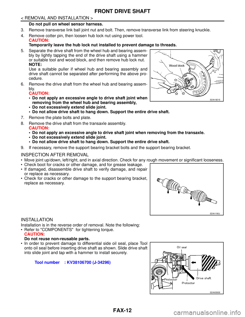
Temporarily leave the hub lock nut installed to prevent damage to threads.
5. Separate the drive shaft from the wheel hub and bearing assem-
bly by lightly tapping the end of the drive shaft using a hammer
or suitable tool and wood block, and then remove hub lock nut.
NOTE:
Use a suitable puller if wheel hub and bearing assembly and
drive shaft cannot be separated after performing the above pro-
cedure.
6. Remove the drive shaft from the wheel hub and bearing assem-
bly.
CAUTION:
Do not apply an excessive angle to drive shaft joint when
removing from the wheel hub and bearing assembly,
Do not excessively extend slide joint.
Do not allow drive shaft to hang down. Support the entire drive shaft.
7. Remove the plate bolts and plate.
8. Remove the drive shaft from the transaxle assembly.
CAUTION:
Do not apply an excessive angle to drive shaft joint when removing from the transaxle.
Do not excessively extend slide joint.
Do not allow drive shaft to hang down. Support the entire drive shaft.
9. If necessary, remove the support bearing bracket bolts and the support bearing bracket.
INSPECTION AFTER REMOVAL
Move joint up/down, left/right, and in axial direction. Check for any rough movement or significant looseness.
Check boot for cracks or other damage, and for grease leakage.
If damaged, disassemble drive shaft to verify damage, and repair
or replace as necessary.
Check for cracks or other damage to the support bearing bracket,
replace as necessary.
INSTALLATION
Installation is in the reverse order of removal. Note the following:
Refer to "COMPONENTS" for tightening torque.
CAUTION:
Do not reuse non-reusable parts.
In order to prevent damage to differential side oil seal, place Tool
onto oil seal before inserting drive shaft as shown. Slide drive shaft
into slide joint and tap with a hammer to install securely.
SDIA1821E
SDIA1190J
Tool number : KV38106700 (J-34296)
SDIA0593E
Page 3177 of 5883
FSU-1
SUSPENSION
C
D
F
G
H
I
J
K
L
M
SECTION FSU
A
B
FSU
N
O
PCONTENTS
FRONT SUSPENSION
PRECAUTION ...............................................2
PRECAUTIONS ...................................................2
Precaution for Supplemental Restraint System
(SRS) "AIR BAG" and "SEAT BELT PRE-TEN-
SIONER" ...................................................................
2
Precaution for Procedure without Cowl Top Cover ......2
Cautions ....................................................................2
PREPARATION ............................................3
PREPARATION ...................................................3
Special Service Tool .................................................3
Commercial Service Tool ..........................................4
SYMPTOM DIAGNOSIS ...............................5
NOISE, VIBRATION AND HARSHNESS
(NVH) TROUBLESHOOTING .............................
5
NVH Troubleshooting Chart ......................................5
ON-VEHICLE MAINTENANCE .....................6
FRONT SUSPENSION ASSEMBLY ...................6
On-Vehicle Inspection and Service ...........................6
Wheel Alignment Inspection ......................................6
ON-VEHICLE REPAIR ..................................9
FRONT SUSPENSION ASSEMBLY ...................9
Component ...............................................................9
REMOVAL AND INSTALLATION ...............11
FRONT SUSPENSION ASSEMBLY .................11
Removal and Installation .........................................11
COIL SPRING AND STRUT ..............................12
Removal and Installation .........................................12
TRANSVERSE LINK .........................................13
Removal and Installation .........................................13
STABILIZER BAR .............................................14
Removal and Installation .........................................14
DISASSEMBLY AND ASSEMBLY ..............15
COIL SPRING AND STRUT ..............................15
Disassembly and Assembly .....................................15
SERVICE DATA AND SPECIFICATIONS
(SDS) ............................................................
17
SERVICE DATA AND SPECIFICATIONS
(SDS) .................................................................
17
Wheel Alignment (Unladen*) ...................................17
Ball Joint ..................................................................18
Wheelarch Height (Unladen*) ..................................18