2007 NISSAN TIIDA light
[x] Cancel search: lightPage 4726 of 5883
![NISSAN TIIDA 2007 Service Repair Manual VEHICLE SECURITY INDICATOR
SEC-101
< COMPONENT DIAGNOSIS >[WITHOUT INTELLIGENT KEY SYSTEM]
C
D
E
F
G
H
I
J
L
MA
B
SEC
N
O
P
VEHICLE SECURITY INDICATOR
DescriptionINFOID:0000000001532075
Vehicle secu NISSAN TIIDA 2007 Service Repair Manual VEHICLE SECURITY INDICATOR
SEC-101
< COMPONENT DIAGNOSIS >[WITHOUT INTELLIGENT KEY SYSTEM]
C
D
E
F
G
H
I
J
L
MA
B
SEC
N
O
P
VEHICLE SECURITY INDICATOR
DescriptionINFOID:0000000001532075
Vehicle secu](/manual-img/5/57395/w960_57395-4725.png)
VEHICLE SECURITY INDICATOR
SEC-101
< COMPONENT DIAGNOSIS >[WITHOUT INTELLIGENT KEY SYSTEM]
C
D
E
F
G
H
I
J
L
MA
B
SEC
N
O
P
VEHICLE SECURITY INDICATOR
DescriptionINFOID:0000000001532075
Vehicle security indicator is located on top left side of the instrument panel near the autolight sensor.
NATS (Nissan Anti-Theft System) and vehicle security system conditions are indicated by blink or illumina-
tion of vehicle security indicator.
Component Function CheckINFOID:0000000001532076
1.CHECK FUNCTION
1. Perform “THEFT IND” in the “Active Test” mode with CONSULT-III.
2. Check vehicle security indicator operation.
Is the inspection result normal?
YES >> INSPECTION END.
NO >> Refer to SEC-101, "
Diagnosis Procedure".
Diagnosis ProcedureINFOID:0000000001532077
1.CHECK SECURITY INDICATOR LAMP POWER SUPPLY CIRCUIT
1. Turn ignition switch OFF.
2. Disconnect security indicator lamp connector.
3. Check voltage between security indicator lamp harness connec-
tor and ground.
Is the inspection result normal?
YES >> GO TO 2.
NO >> Repair or replace harness.
2.CHECK SECURITY INDICATOR LAMP SIGNAL CIRCUIT
1. Disconnect BCM connector.
Te s t i t e m D e s c r i p t i o n
THEFT INDON
Vehicle security indicatorON
OFF OFF
ALKIA0846ZZ
Te r m i n a l s
Voltage (V)
(Approx.) (+)
(–)
security indicator lamp connector Terminal
M31 1 Ground Battery voltage
Page 4737 of 5883
![NISSAN TIIDA 2007 Service Repair Manual SEC-112
< ECU DIAGNOSIS >[WITHOUT INTELLIGENT KEY SYSTEM]
BCM (BODY CONTROL MODULE)
REAR WIPER CONTROL
BCM detects a rear wiper stopping position according to a rear wiper auto stop signal.
When a rea NISSAN TIIDA 2007 Service Repair Manual SEC-112
< ECU DIAGNOSIS >[WITHOUT INTELLIGENT KEY SYSTEM]
BCM (BODY CONTROL MODULE)
REAR WIPER CONTROL
BCM detects a rear wiper stopping position according to a rear wiper auto stop signal.
When a rea](/manual-img/5/57395/w960_57395-4736.png)
SEC-112
< ECU DIAGNOSIS >[WITHOUT INTELLIGENT KEY SYSTEM]
BCM (BODY CONTROL MODULE)
REAR WIPER CONTROL
BCM detects a rear wiper stopping position according to a rear wiper auto stop signal.
When a rear wiper auto stop signal is in the condition listed below, BCM stops power supply to rear wiper after
rear wiper is activated for five seconds.
NOTE:
The above operation is repeated when operating the rear wiper switch one minute after the stop of the rear
wiper caused by Fail-safe.
TURN SIGNAL LAMP CONTROL
BCM detects the turn signal lamp circuit status from the terminal voltage.
BCM increases the turn signal lamp blinking speed if the bulb or harness open is detected with the turn signal
lamp operating.
NOTE:
The blinking speed is normal while activating the hazard warning lamp.
LIGHT & RAIN SENSOR MALFUNCTION DETECTION FUNCTION
BCM controls the following items when LIGHT & RAIN sensor has a malfunction.
Auto Light Control
Headlamp is turned ON.
Front Wiper Control
The condition just before the activation of Fail-safe is maintained until the front wiper switch is turned OFF.
Display contents of CONSULT Fail-safe Cancellation
B2190: NATS ANTENNA AMP Inhibits engine cranking
Inhibits steering lock unlocking (Intelligent Key unit)
Fuel cut (ECM)Erase DTC
B2191: DIFFERENCE OF KEY Inhibits engine cranking
Inhibits steering lock unlocking (Intelligent Key unit)
Fuel cut (ECM)Erase DTC
B2192: ID DISCORD BCM-ECM Fuel cut (ECM) Erase DTC
B2193: CHAIN OF BCM-ECM Fuel cut (ECM) Erase DTC
B2194: DISCORD BCM-I-KEY Inhibits engine cranking
Inhibits steering lock unlocking (Intelligent Key unit)
Fuel cut (ECM)Erase DTC
B2195: ANTI SCANNING Inhibits engine cranking
Inhibits steering lock unlocking (Intelligent Key unit)
Fuel cut (ECM)Erase DTC
B2196: DONGLE NG Inhibits engine cranking
Inhibits steering lock unlocking (Intelligent Key unit)
Fuel cut (ECM)Erase DTC
Ignition switch Rear wiper switch Auto stop signal
ONOFFRear wiper stop position signal cannot be
input 5 seconds.
ON The signal does not change for 5 seconds.
Page 4750 of 5883
SPIRAL CABLE
SR-7
< ON-VEHICLE REPAIR >
C
D
E
F
G
I
J
K
L
MA
B
SR
N
O
P
SPIRAL CABLE
Removal and InstallationINFOID:0000000001404300
REMOVAL
WARNING:
When servicing the SRS, do not work from directly in front of air bag module.
CAUTION:
Before servicing the SRS, turn ignition switch OFF, disconnect both battery cables and wait at least
3 minutes.
Do not tap or bump the steering wheel.
Do not disassemble the spiral cable.
Do not allow oil, grease or water to come in contact with the spiral cable.
Replace the spiral cable if it has been dropped or sustained an impact.
With the steering linkage disconnected, the spiral cable may snap by turning the steering wheel
beyond the limited number of turns. The spiral cable can be turned counterclockwise about 2.5 turns
from the neutral position.
1. Disconnect the negative and positive battery cables, then wait at least 3 minutes.
2. Set the front wheels to the straight-ahead/neutral position.
3. Remove the steering wheel. Refer to ST-8, "
Removal and Installation".
4. Remove the column cover upper and lower.
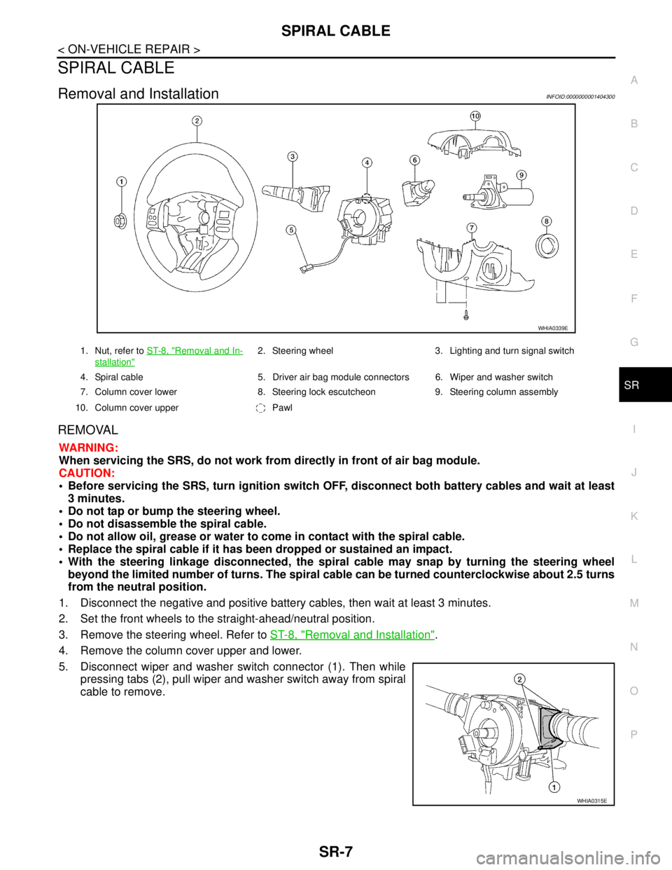
5. Disconnect wiper and washer switch connector (1). Then while
pressing tabs (2), pull wiper and washer switch away from spiral
cable to remove.
WHIA0339E
1. Nut, refer to ST-8, "Removal and In-
stallation"
2. Steering wheel 3. Lighting and turn signal switch
4. Spiral cable 5. Driver air bag module connectors 6. Wiper and washer switch
7. Column cover lower 8. Steering lock escutcheon 9. Steering column assembly
10. Column cover upper Pawl
WHIA0315E
Page 4751 of 5883
SR-8
< ON-VEHICLE REPAIR >
SPIRAL CABLE
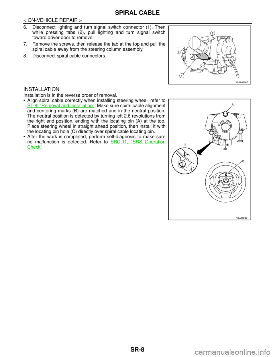
6. Disconnect lighting and turn signal switch connector (1). Then
while pressing tabs (2), pull lighting and turn signal switch
toward driver door to remove.
7. Remove the screws, then release the tab at the top and pull the
spiral cable away from the steering column assembly.
8. Disconnect spiral cable connectors.
INSTALLATION
Installation is in the reverse order of removal.
Align spiral cable correctly when installing steering wheel, refer to
ST-8, "
Removal and Installation". Make sure spiral cable alignment
and centering marks (B) are matched and in the neutral position.
The neutral position is detected by turning left 2.6 revolutions from
the right end position, ending with the locating pin (A) at the top.
Place steering wheel in straight ahead position, then install it with
the locating pin hole (C) directly over spiral cable locating pin.
After the work is completed, perform self-diagnosis to make sure
no malfunction is detected. Refer to SRC-11, "
SRS Operation
Check".
WHIA0316E
PHIA1024J
Page 4759 of 5883
SR-16
< ON-VEHICLE REPAIR >
DISPOSAL OF AIR BAG MODULE AND SEAT BELT PRE-TENSIONER
DISPOSAL OF AIR BAG MODULE AND SEAT BELT PRE-TENSIONER
Caution for Air Bag Module and Seat Belt Pre-tensionerINFOID:0000000001404296
Before disposing of air bag module and seat belt pre-tensioner, or vehicles equipped with such systems,
deploy the systems. If such systems have already been deployed due to an accident, dispose of them as
indicated in Disposing of Air Bag Module and Seat Belt Pre-tensioner.
When deploying the air bag module and seat belt pre-tensioner,always use the Special Service Tool; Deploy-
ment tool (SST: KV99106400).
When deploying the air bag module and seat belt pre-tensioner,stand at least 5 m (16 ft) away from the
deployment component.
When deploying air bag module and seat belt pre-tensioner, a fairlyloud noise is made, followed by smoke
being released. The smoke is not poisonous,however, be careful not to inhale smoke since it irritates the
throat and can cause choking.
Always activate one air bag module at a time.
Due to heat, leave air bag module unattended for more than 30 minutes after deployment. Also leave seat
belt pre-tensioner unattended for more than 10 minutes after deployment.
Wear gloves when handling a deployed air bag module and seat belt pre-tensioner.
Never apply water to the deployed air bag module and seat belt pre-tensioner.
Wash your hands after finishing work.
Place the vehicle outdoors with an open space of at least 6 m (20 ft) on all sides when deploying air bag
module and seat belt pre-tensioner while mounted in vehicle.
Use a volt meter to make sure the vehicle battery is fully charged.
Do not dispose of the air bag module and seat belt pre-tensioner undeployed.
CHECKING DEPLOYMENT TOOL
Connecting to Battery
CAUTION:
The battery must show voltage of 9.6 V or more.
Remove the battery from the vehicle and place it on dry wood blocks
approximately 5 m (16 ft) away from the vehicle.
Wait 3 minutes after the vehicle battery is disconnected before pro-
ceeding.
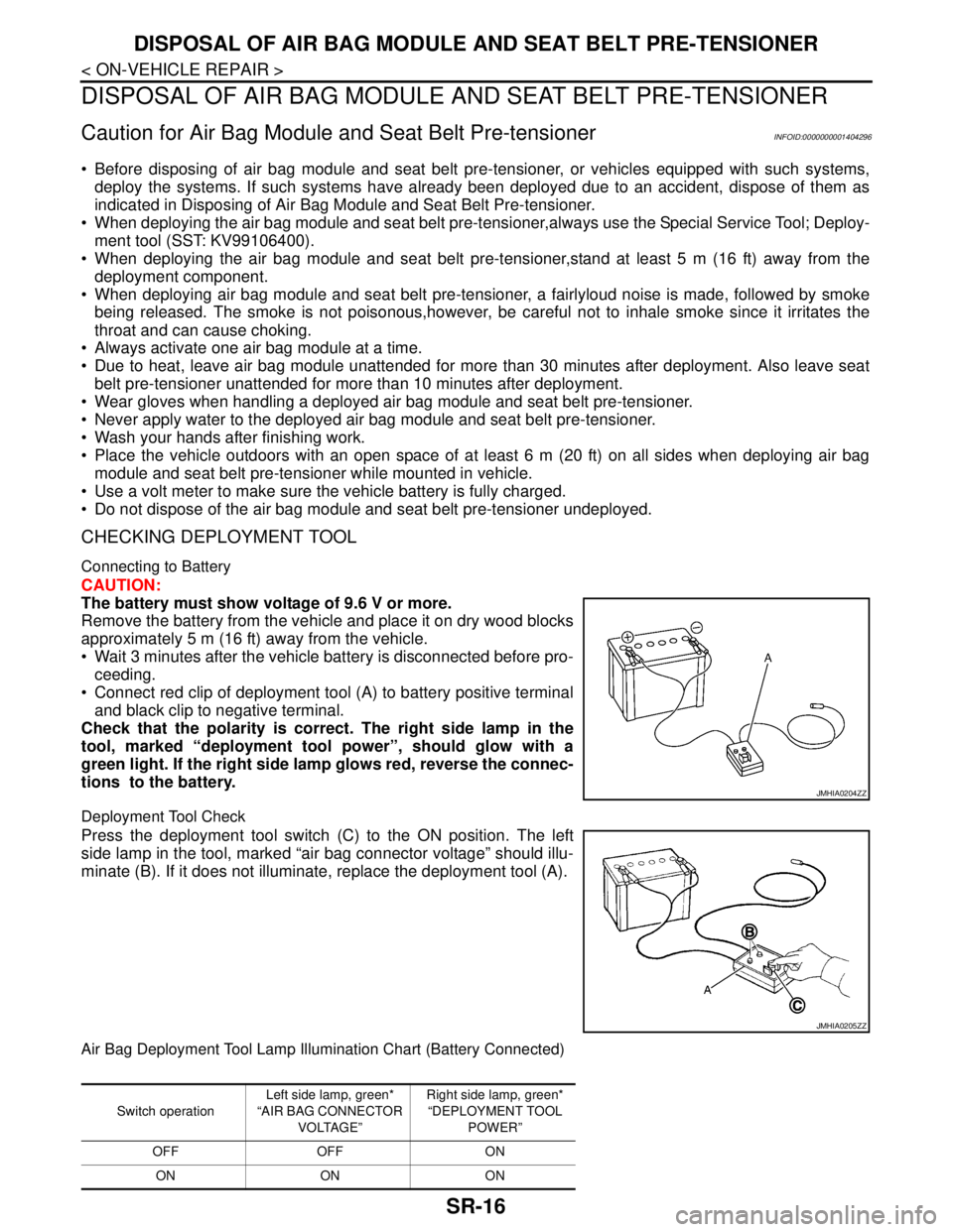
Connect red clip of deployment tool (A) to battery positive terminal
and black clip to negative terminal.
Check that the polarity is correct. The right side lamp in the
tool, marked “deployment tool power”, should glow with a
green light. If the right side lamp glows red, reverse the connec-
tions to the battery.
Deployment Tool Check
Press the deployment tool switch (C) to the ON position. The left
side lamp in the tool, marked “air bag connector voltage” should illu-
minate (B). If it does not illuminate, replace the deployment tool (A).
Air Bag Deployment Tool Lamp Illumination Chart (Battery Connected)
JMHIA0204ZZ
JMHIA0205ZZ
Switch operationLeft side lamp, green*
“AIR BAG CONNECTOR
VOLTAGE”Right side lamp, green*
“DEPLOYMENT TOOL
POWER”
OFF OFF ON
ON ON ON
Page 4782 of 5883
ON BOARD DIAGNOSTIC (OBD) SYSTEM
SRC-13
< FUNCTION DIAGNOSIS >
C
D
E
F
G
I
J
K
L
MA
B
SRC
N
O
P
Trouble Diagnosis without CONSULT-IIIINFOID:0000000001396362
DIAGNOSTIC PROCEDURE 6
Inspect SRS Malfunction Using "AIR BAG" Warning Lamp—Diagnosis Mode
NOTE:
SRS will not enter Diagnosis mode if no malfunction is detected in User mode.
1. Turn ignition switch ON.
2. After “AIR BAG” warning lamp lights for 7 seconds, turn ignition switch OFF within 1 second.
3. Wait more than 3 seconds.
4. Repeat steps 1 to 3 two more times (3 times total).
5. Turn ignition switch ON.
SRS is now in Diagnosis mode. Refer to SRC-13, "
Trouble Diagnosis without CONSULT-III".
CONSULT-III Function (AIR BAG)INFOID:0000000001396363
CONSULT-III can display each diagnostic item using the diagnostic test modes shown following.
Self-Diagnosis Function (Without CONSULT-III)INFOID:0000000001396364
The reading of these results is accomplished using one of two modes —“User mode” and “Diagnosis mode”.
After a malfunction is repaired, turn the ignition switch OFF for at least one second, then back ON. Diagnosis
mode returns to the User mode. At that time, the self-diagnostic result is cleared.
AIR BAG diagnostic mode Description
SELF-DIAG [CURRENT]A current Self-diagnosis result (also indicated by the number of warning lamp flashes in the Diagnosis
mode) is displayed on the CONSULT-III screen in real time. This refers to a malfunctioning part requir-
ing repairs.
SELF-DIAG [PAST]Diagnosis results previously stored in the memory are displayed on the CONSULT-III screen. The
stored results will remain until memory erasing is executed.
TROUBLE DIAG RECORDWith TROUBLE DIAG RECORD, diagnosis results previously erased by a reset operation can be dis-
played on the CONSULT-III screen.
ECU DISCRIMINATED NO.The air bag diagnosis sensor unit for each vehicle model is assigned with its own, individual classifica-
tion number. This number will be displayed on the CONSULT-III screen, as shown. When replacing the
air bag diagnosis sensor unit, refer to the part number for the compatibility. After installation, replace-
ment with a correct unit can be checked by confirming this classification number on the CONSULT-III
screen.
The air bag diagnosis sensor unit discriminated numbers assigned are:
A60C (LHD vehicles with front side air bags only)
A60A (RHD vehicles with front side air bags only)
A60E (LHD vehicles with front side and side curtain air bags)
A60B (RHD vehicles with front side and side curtain air bags)
A611 (vehicles without front side and side curtain air bags)
PASSENGER AIR BAGThe STATUS (readiness) of the front passenger air bag module is displayed. The STATUS displayed
(ON/OFF) depends on the signals supplied to the air bag diagnosis sensor unit from the passenger air
bag deactivation switch. Refer to SRC-8, "
Passenger Air Bag Deactivation Switch" for more informa-
tion.
Page 4785 of 5883
SRC-16
< COMPONENT DIAGNOSIS >
B1049 - B1052 DRIVER AIR BAG MODULE
3.DTC
If DTC is detected. Refer to SRC-16, "
DiagnosisProcedure(Componentdiagnosis)".
>>END
DTC CONFIRMATION PROCEDURE (Without CONSULT-lll)
NOTE:
SRS will not enter diagnosis mode if no malfunction is detected in user mode.
1.IGNITION SWITCH
Turn ignition switch ON.
>> GO TO 2
2.IGNITION SWITCH
After air bag warning lamp lights for 7 seconds, turn ignition switch OFF within 1 second.
>> GO TO 3
3.WAIT TIME
Wait more than 3 seconds.
>> GO TO 4
4.REPEAT STEPS
Repeat steps 1 to 3 twice.
>> GO TO 5.
5.IGNITION SWITCH
Turn ignition switch ON.
>> GO TO 6.
6.DIAGNOSTIC MODE
SRS system is now in diagnostic mode and AIR BAG warning lamp flashes. Refer to SRC-13, "
Trouble Diag-
nosis without CONSULT-III".
>>END
Diagnosis Procedure (Component diagnosis)INFOID:0000000001396367
Recheck SRS after each replacement.
1.HARNESS CONNECTOR
Is there any visible damage to the connector?
YES or NO
YES >> Replace the harness.
NO >> GO TO 2
2.WIRING HARNESS
Is there any visible damage to the harness?
YES or NO
YES >> Replace the harness.
NO >> GO TO 3
Page 4788 of 5883
B1065 - B1068 PASSENGER AIR BAG MODULE
SRC-19
< COMPONENT DIAGNOSIS >
C
D
E
F
G
I
J
K
L
MA
B
SRC
N
O
P
DTC CONFIRMATION PROCEDURE (Without CONSULT-lll)
NOTE:
SRS will not enter diagnosis mode if no malfunction is detected in user mode.
1.IGNITION SWITCH
Turn ignition switch ON.
>> GO TO 2
2.IGNITION SWITCH
After air bag warning lamp lights for 7 seconds, turn ignition switch OFF within 1 second.
>> GO TO 3
3.WAIT TIME
Wait more than 3 seconds.
>> GO TO 4
4.REPEAT STEPS
Repeat steps 1 to 3 twice.
>> GO TO 5
5.IGNITION SWITCH
Turn ignition switch ON.
>> GO TO 6
6.DIAGNOSTIC MODE
SRS system is now in diagnostic mode and AIR BAG warning lamp flashes. Refer to SRC-13, "
Trouble Diag-
nosis without CONSULT-III".
>>END
Diagnosis Procedure (Component diagnosis)INFOID:0000000001396370
Recheck SRS after each replacement.
1.HARNESS CONNECTOR
Is there any visible damage to the connector?
YES or NO
YES >> Replace the harness.
NO >> GO TO 2
2.WIRING HARNESS
Is there any visible damage to the harness?
YES or NO
YES >> Replace the harness.
NO >> GO TO 3
3.FRONT PASSENGER AIR BAG MODULE
Replace the front passenger air bag module. Refer to SR-9, "
Removal and Installation".
>> GO TO 4
4.AIR BAG DIAGNOSIS SENSOR UNIT