2007 NISSAN TIIDA light
[x] Cancel search: lightPage 4815 of 5883

SRC-46
< COMPONENT DIAGNOSIS >
B1118 – B1120 SATELLITE SENSOR LH
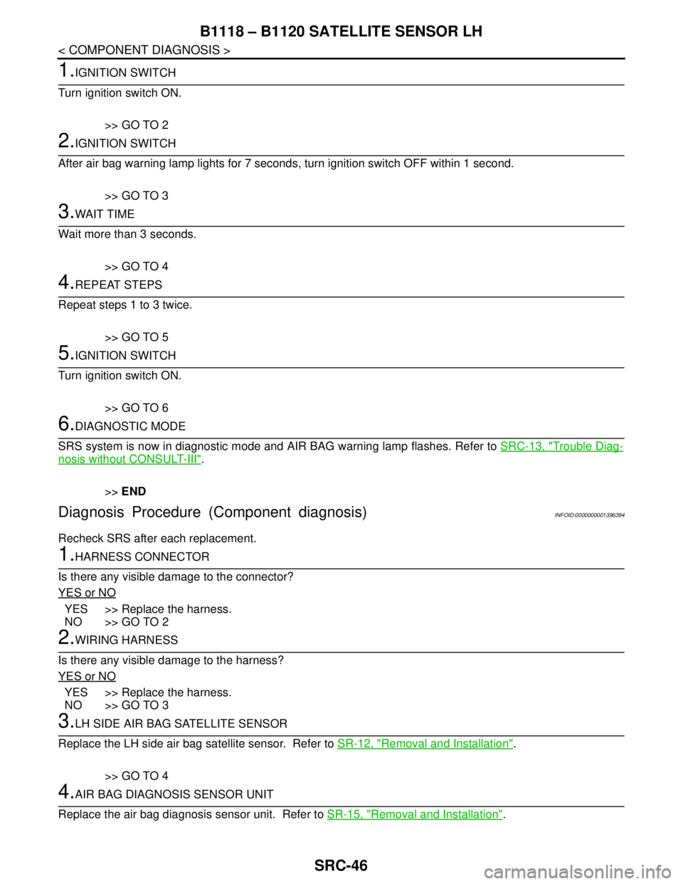
1.IGNITION SWITCH
Turn ignition switch ON.
>> GO TO 2
2.IGNITION SWITCH
After air bag warning lamp lights for 7 seconds, turn ignition switch OFF within 1 second.
>> GO TO 3
3.WAIT TIME
Wait more than 3 seconds.
>> GO TO 4
4.REPEAT STEPS
Repeat steps 1 to 3 twice.
>> GO TO 5
5.IGNITION SWITCH
Turn ignition switch ON.
>> GO TO 6
6.DIAGNOSTIC MODE
SRS system is now in diagnostic mode and AIR BAG warning lamp flashes. Refer to SRC-13, "
Trouble Diag-
nosis without CONSULT-III".
>>END
Diagnosis Procedure (Component diagnosis)INFOID:0000000001396394
Recheck SRS after each replacement.
1.HARNESS CONNECTOR
Is there any visible damage to the connector?
YES or NO
YES >> Replace the harness.
NO >> GO TO 2
2.WIRING HARNESS
Is there any visible damage to the harness?
YES or NO
YES >> Replace the harness.
NO >> GO TO 3
3.LH SIDE AIR BAG SATELLITE SENSOR
Replace the LH side air bag satellite sensor. Refer to SR-12, "
Removal and Installation".
>> GO TO 4
4.AIR BAG DIAGNOSIS SENSOR UNIT
Replace the air bag diagnosis sensor unit. Refer to SR-15, "
Removal and Installation".
Page 4818 of 5883

B1113 – B1115 SATELLITE SENSOR RH
SRC-49
< COMPONENT DIAGNOSIS >
C
D
E
F
G
I
J
K
L
MA
B
SRC
N
O
P
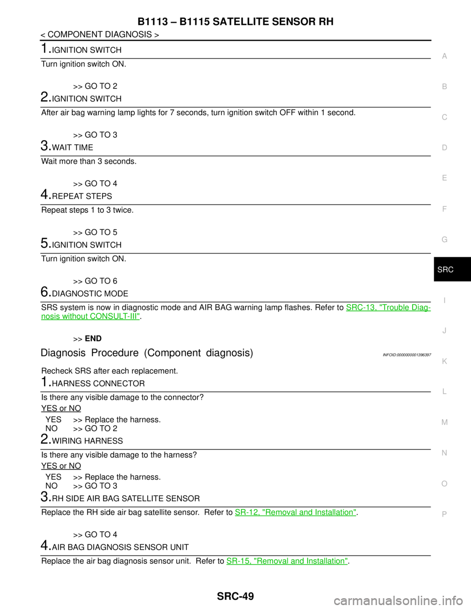
1.IGNITION SWITCH
Turn ignition switch ON.
>> GO TO 2
2.IGNITION SWITCH
After air bag warning lamp lights for 7 seconds, turn ignition switch OFF within 1 second.
>> GO TO 3
3.WAIT TIME
Wait more than 3 seconds.
>> GO TO 4
4.REPEAT STEPS
Repeat steps 1 to 3 twice.
>> GO TO 5
5.IGNITION SWITCH
Turn ignition switch ON.
>> GO TO 6
6.DIAGNOSTIC MODE
SRS system is now in diagnostic mode and AIR BAG warning lamp flashes. Refer to SRC-13, "
Trouble Diag-
nosis without CONSULT-III".
>>END
Diagnosis Procedure (Component diagnosis)INFOID:0000000001396397
Recheck SRS after each replacement.
1.HARNESS CONNECTOR
Is there any visible damage to the connector?
YES or NO
YES >> Replace the harness.
NO >> GO TO 2
2.WIRING HARNESS
Is there any visible damage to the harness?
YES or NO
YES >> Replace the harness.
NO >> GO TO 3
3.RH SIDE AIR BAG SATELLITE SENSOR
Replace the RH side air bag satellite sensor. Refer to SR-12, "
Removal and Installation".
>> GO TO 4
4.AIR BAG DIAGNOSIS SENSOR UNIT
Replace the air bag diagnosis sensor unit. Refer to SR-15, "
Removal and Installation".
Page 4821 of 5883

SRC-52
< COMPONENT DIAGNOSIS >
B1XXX AIR BAG DIAGNOSIS SENSOR UNIT
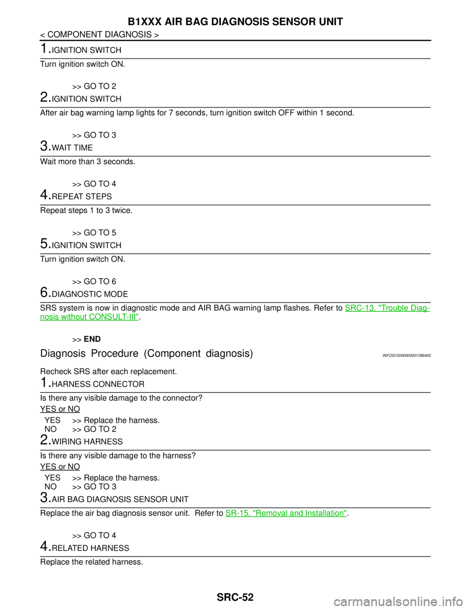
1.IGNITION SWITCH
Turn ignition switch ON.
>> GO TO 2
2.IGNITION SWITCH
After air bag warning lamp lights for 7 seconds, turn ignition switch OFF within 1 second.
>> GO TO 3
3.WAIT TIME
Wait more than 3 seconds.
>> GO TO 4
4.REPEAT STEPS
Repeat steps 1 to 3 twice.
>> GO TO 5
5.IGNITION SWITCH
Turn ignition switch ON.
>> GO TO 6
6.DIAGNOSTIC MODE
SRS system is now in diagnostic mode and AIR BAG warning lamp flashes. Refer to SRC-13, "
Trouble Diag-
nosis without CONSULT-III".
>>END
Diagnosis Procedure (Component diagnosis)INFOID:0000000001396400
Recheck SRS after each replacement.
1.HARNESS CONNECTOR
Is there any visible damage to the connector?
YES or NO
YES >> Replace the harness.
NO >> GO TO 2
2.WIRING HARNESS
Is there any visible damage to the harness?
YES or NO
YES >> Replace the harness.
NO >> GO TO 3
3.AIR BAG DIAGNOSIS SENSOR UNIT
Replace the air bag diagnosis sensor unit. Refer to SR-15, "
Removal and Installation".
>> GO TO 4
4.RELATED HARNESS
Replace the related harness.
Page 4861 of 5883

ST-6
< ON-VEHICLE MAINTENANCE >
STEERING WHEEL
ON-VEHICLE MAINTENANCE
STEERING WHEEL
On-Vehicle Inspection and ServiceINFOID:0000000001282496
CHECKING CONDITION OF INSTALLATION
Check installation conditions of steering gear assembly, front suspension assembly, axle and steering col-
umn assembly.
Check if movement exists when steering wheel is moved up and down, to the left and right and to the axial
direction.
Check steering gear assembly mounting bolts and nuts for looseness. Refer to ST-12, "
Removal and Instal-
lation" .
CHECKING STEERING WHEEL PLAY
Turn steering wheel so that front wheels come to the straight-ahead position. Start engine and lightly turn
steering wheel to the left and right until front wheels start to move. Measure steering wheel movement on the
outer circumference.
When the measurement value is outside the standard value, check backlash for each joint of steering col-
umn assembly and installation condition of steering gear assembly.
CHECKING NEUTRAL POSITION STEERING WHEEL
Make sure that steering gear assembly, steering column assembly and steering wheel are installed in the
correct position.
Perform neutral position inspection after wheel alignment. Refer to SR-2, "
Precaution for Supplemental
Restraint System (SRS) "AIR BAG" and "SEAT BELT PRE-TENSIONER"" .
Set vehicle to the straight-ahead position and confirm steering wheel is in the neutral position.
Loosen outer socket lock nut and turn inner socket to left and right equally to make fine adjustments if steer-
ing wheel is not in the neutral position.
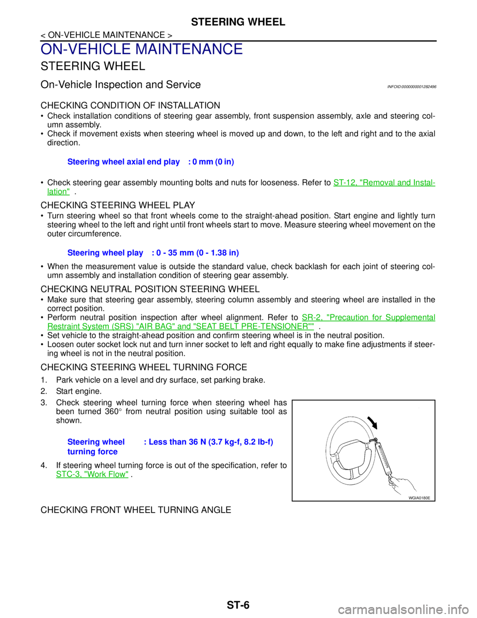
CHECKING STEERING WHEEL TURNING FORCE
1. Park vehicle on a level and dry surface, set parking brake.
2. Start engine.
3. Check steering wheel turning force when steering wheel has
been turned 360° from neutral position using suitable tool as
shown.
4. If steering wheel turning force is out of the specification, refer to
STC-3, "
Work Flow" .
CHECKING FRONT WHEEL TURNING ANGLE
Steering wheel axial end play : 0 mm (0 in)
Steering wheel play : 0 - 35 mm (0 - 1.38 in)
Steering wheel
turning force: Less than 36 N (3.7 kg-f, 8.2 lb-f)
WGIA0180E
Page 4876 of 5883

STC-2
EPS WARNING LAMP DOES NOT TURN ON ...30
Diagnosis Procedure ..............................................30
EPS WARNING LAMP DOES NOT TURN
OFF ....................................................................
31
Diagnosis Procedure ..............................................31
STEERING WHEEL TURNING FORCE IS
HEAVY OR LIGHT .............................................
33
Diagnosis Procedure ..............................................33
UNBALANCE STEERING WHEEL TURNING
FORCE AND RETURN BETWEEN RIGHT
AND LEFT ..........................................................
34
Diagnosis Procedure ..............................................34
UNBALANCE STEERING WHEEL TURNING
FORCE (TORQUE VARIATION) .......................
35
Diagnosis Procedure ...............................................35
PRECAUTION ............................................36
PRECAUTIONS .................................................36
Precaution for Supplemental Restraint System
(SRS) "AIR BAG" and "SEAT BELT PRE-TEN-
SIONER" .................................................................
36
Precaution Necessary for Steering Wheel Rota-
tion After Battery Disconnect ..................................
36
Service Notice or Precaution for EPS System ........36
Page 4903 of 5883
![NISSAN TIIDA 2007 Service Repair Manual EPS SYSTEM SYMPTOMS
STC-29
< SYMPTOM DIAGNOSIS >[EPS]
C
D
E
F
H
I
J
K
L
MA
B
STC
N
O
P
SYMPTOM DIAGNOSIS
EPS SYSTEM SYMPTOMS
Symptom ChartINFOID:0000000001716771
If EPS warning lamp turns ON, perform NISSAN TIIDA 2007 Service Repair Manual EPS SYSTEM SYMPTOMS
STC-29
< SYMPTOM DIAGNOSIS >[EPS]
C
D
E
F
H
I
J
K
L
MA
B
STC
N
O
P
SYMPTOM DIAGNOSIS
EPS SYSTEM SYMPTOMS
Symptom ChartINFOID:0000000001716771
If EPS warning lamp turns ON, perform](/manual-img/5/57395/w960_57395-4902.png)
EPS SYSTEM SYMPTOMS
STC-29
< SYMPTOM DIAGNOSIS >[EPS]
C
D
E
F
H
I
J
K
L
MA
B
STC
N
O
P
SYMPTOM DIAGNOSIS
EPS SYSTEM SYMPTOMS
Symptom ChartINFOID:0000000001716771
If EPS warning lamp turns ON, perform self-diagnosis. Refer to STC-7, "CONSULT-III Function (EPS)".
Symptom Condition Check item Reference page
EPS warning lamp does not turn ON when ig-
nition switch to “ON”.
(EPS warning lamp check)Ignition switch: ONCAN communication line
STC-30
Combination meter
EPS warning lamp does not turn OFF for sev-
eral seconds after starting the engineEngine runningCAN communication line
STC-31
Power supply and ground for
EPS control unit
Torque sensor
EPS motor
Vehicle speed signal
Engine status signal
Combination meter
Steering wheel turning force is heavy or light,
while driving While driving
Steering wheel turningCAN communication line
STC-33
Vehicle speed signal
Engine status signal
EPS motor
Steering wheel turning force
(Mechanical malfunction)
Unbalance steering wheel turning force and
return between right and left, while driving While driving
Steering wheel turningWheel alignment
STC-34
Steering wheel turning force
(Mechanical malfunction)
Unbalance steering wheel turning force,
while driving (Torque variation) While driving
Steering wheel turningSteering column intermediate
shaft installation condition
STC-35
Steering wheel turning force
(Mechanical malfunction)
Page 4907 of 5883
![NISSAN TIIDA 2007 Service Repair Manual STEERING WHEEL TURNING FORCE IS HEAVY OR LIGHT
STC-33
< SYMPTOM DIAGNOSIS >[EPS]
C
D
E
F
H
I
J
K
L
MA
B
STC
N
O
P
STEERING WHEEL TURNING FORCE IS HEAVY OR LIGHT
Diagnosis ProcedureINFOID:0000000001697 NISSAN TIIDA 2007 Service Repair Manual STEERING WHEEL TURNING FORCE IS HEAVY OR LIGHT
STC-33
< SYMPTOM DIAGNOSIS >[EPS]
C
D
E
F
H
I
J
K
L
MA
B
STC
N
O
P
STEERING WHEEL TURNING FORCE IS HEAVY OR LIGHT
Diagnosis ProcedureINFOID:0000000001697](/manual-img/5/57395/w960_57395-4906.png)
STEERING WHEEL TURNING FORCE IS HEAVY OR LIGHT
STC-33
< SYMPTOM DIAGNOSIS >[EPS]
C
D
E
F
H
I
J
K
L
MA
B
STC
N
O
P
STEERING WHEEL TURNING FORCE IS HEAVY OR LIGHT
Diagnosis ProcedureINFOID:0000000001697735
SYMPTOM:
Steering wheel turning force is heavy or light, while driving.
DIAGNOSTIC PROCEDURE
1.CHECK SYSTEM FOR CAN COMMUNICATION LINE
Perform self-diagnosis. Refer to STC-7, "
CONSULT-III Function (EPS)".
Is the
“CAN COMM CIRCUIT [U1000]” displayed?
YES >> Perform trouble diagnosis for CAN communication line. Refer to STC-21, "Diagnosis Procedure".
NO >> GO TO 2.
2.CHECK VEHICLE SPEED SIGNAL
Perform self-diagnosis with ABS actuator and electric unit (control unit). Refer to BRC-25, "
CONSULT-III
Function (ABS)" (with ABS) or BRC-105, "CONSULT-III Function (ABS)" (with ESP).
Is any malfunction detected by self-diagnosis?
YES >> Check the malfunctioning system.
NO >> GO TO 3.
3.CHECK COMBINATION METER SIGNAL
Perform self-diagnosis with combination meter. Refer to MWI-22, "
CONSULT-III Function (METER/M&A)".
Is any malfunction detected by self-diagnosis?
YES >> Check the malfunctioning system.
NO >> GO TO 4.
4.CHECK ENGINE STATUS SIGNAL
Perform self-diagnosis for ECM. Refer to EC-107, "
CONSULT-III Function" (HR16DE with EURO-OBD), EC-
462, "CONSULT-III Function" (HR16DE without EURO-OBD), EC-772, "CONSULT-III Function" (MR18DE),
EC-1104, "
Diagnosis Description" (K9K).
Is any malfunction detected by self-diagnosis?
YES >> Check the malfunctioning system.
NO >> GO TO 5.
5.CHECK EPS MOTOR SYSTEM
Perform trouble diagnosis for EPS motor. Refer to STC-13, "
Diagnosis Procedure".
OK or NG
OK >> GO TO 6.
NG >> Repair or replace damaged parts.
6.CHECK EPS CONTROL UNIT
Check EPS control unit input/output signal. Refer to STC-22, "
EPS Control Unit Input/Output Signal Reference
Va l u e".
OK or NG
OK >> GO TO 7.
NG >> Check EPS control unit pin terminals for damage or loose connection with harness connector. If
any items are damaged, repair or replace damaged parts.
7.SYMPTOM CHECK
Check again.
OK or NG
OK >>INSPECTION END
NG >> Check the steering wheel turning force because there may be mechanical malfunction. Refer to
ST-6, "
On-Vehicle Inspection and Service".
Page 4949 of 5883

TM-3
C
E
F
G
H
I
J
K
L
MA
B
TM
N
O
P
DTC TURBINE REVOLUTION SENSOR .........104
Description ............................................................104
CONSULT-III Reference Value in Data Monitor
Mode .....................................................................
104
On Board Diagnosis Logic ....................................104
Possible Cause .....................................................104
DTC Confirmation Procedure ................................104
Diagnosis Procedure .............................................104
CONTROL UNIT (RAM), CONTROL UNIT
(ROM) ...............................................................
108
Description ............................................................108
On Board Diagnosis Logic ....................................108
Possible Cause .....................................................108
DTC Confirmation Procedure ................................108
Diagnosis Procedure .............................................108
MAIN POWER SUPPLY AND GROUND CIR-
CUIT ..................................................................
109
Description ............................................................109
On Board Diagnosis Logic ....................................109
Possible Cause .....................................................109
DTC Confirmation Procedure ................................109
Diagnosis Procedure .............................................109
PNP, OD SWITCH AND CLOSED THROT-
TLE, WIDE OPEN THROTTLE POSITION
SIGNAL CIRCUIT .............................................
111
CONSULT-III Reference Value in Data Monitor
Mode .....................................................................
111
TCM Terminal and Reference Value .....................111
Diagnosis Procedure .............................................111
Component Inspection ..........................................115
A/T SHIFT LOCK SYSTEM ..............................116
Wiring Diagram - A/T Shift Lock System - .............116
Terminals And Reference Values .........................116
Diagnosis Procedure .............................................117
ECU DIAGNOSIS .......................................119
TCM ..................................................................119
Reference Value ...................................................119
Wiring Diagram - A/T CONTROL SYSTEM - ........123
Fail-Safe ................................................................123
DTC Inspection Priority Chart ...............................125
DTC Index .............................................................125
DTC Alphabetical Index ........................................126
SYMPTOM DIAGNOSIS ............................127
SYSTEM SYMPTOM ........................................127
Symptom Chart .....................................................127
OD OFF Indicator Lamp Does Not Come On .......138
Engine Cannot Be Started in "P" and "N" Position ..140
In "P" Position, Vehicle Moves Forward or Back-
ward When Pushed ...............................................
140
In "N" Position, Vehicle Moves ..............................141
Large Shock "N" → "R" Position ...........................142
Vehicle Does Not Creep Backward in "R" Position ..142
Vehicle Does Not Creep Forward in "D", "2" or "1"
Position ..................................................................
144
Vehicle Cannot Be Started from D1 .......................145
A/T Does Not Shift: D1→ D2or Does Not Kick-
down: D
4→ D2 .......................................................146
A/T Does Not Shift: D2→ D3 ..................................148
A/T Does Not Shift: D3→ D4 ..................................149
A/T Does Not Perform Lock-up .............................151
A/T Does Not Hold Lock-up Condition ...................151
Lock-up Is Not Released .......................................152
Engine Speed Does Not Return to Idle (Light
Braking D
4→ D3) ...................................................153
A/T Does Not Shift: D4→ D3, When OD OFF ........154
A/T Does Not Shift: D3→ 22, When Selector Lever
"D" → "2" Position .................................................
155
A/T Does Not Shift: 22→ 11, When Selector Lever
"2" → "1" Position ..................................................
156
Vehicle Does Not Decelerate by Engine Brake .....158
TCM Self-Diagnosis Does Not Activate .................161
PRECAUTION ............................................163
PRECAUTIONS ...............................................163
Precaution for Supplemental Restraint System
(SRS) "AIR BAG" and "SEAT BELT PRE-TEN-
SIONER" ...............................................................
163
Precaution Necessary for Steering Wheel Rota-
tion After Battery Disconnect .................................
163
Precaution for On Board Diagnosis (OBD) System
of A/T and Engine (For Type1 Only) ......................
163
Precaution .............................................................164
Service Notice or Precaution .................................165
Wiring Diagram and Trouble Diagnosis .................165
PREPARATION .........................................166
PREPARATION ...............................................166
Special Service Tool ..............................................166
Commercial Service Tool ......................................169
ON-VEHICLE MAINTENANCE ..................171
A/T FLUID .......................................................171
Checking A/T Fluid ................................................171
Changing A/T Fluid ................................................171
A/T Fluid Cooler Cleaning .....................................172
STALL TEST ...................................................175
Inspection and Judgment ......................................175
LINE PRESSURE TEST ..................................178
Inspection and Judgment ......................................178
ROAD TEST ....................................................180
Description .............................................................180
Check Before Engine Is Started ............................180
Check at Idle ..........................................................181
Cruise Test - Part 1 ...............................................183
Cruise Test - Part 2 ...............................................185
Cruise Test - Part 3 ...............................................186
Vehicle Speed When Shifting Gears .....................188