2007 NISSAN TIIDA checking oil
[x] Cancel search: checking oilPage 3195 of 5883

GI-1
GENERAL INFORMATION
C
D
E
F
G
H
I
J
K
L
MB
GI
SECTION GI
N
O
P
CONTENTS
GENERAL INFORMATION
HOW TO USE THIS MANUAL ......................3
HOW TO USE THIS MANUAL ............................3
Description ................................................................3
Terms ........................................................................3
Units ..........................................................................3
Contents ....................................................................3
Relation between Illustrations and Descriptions .......4
Component ................................................................4
How to Follow Trouble Diagnosis ..............................5
How to Read Wiring Diagram ....................................9
Abbreviations ..........................................................16
HOW TO FOLLOW TROUBLE DIAGNOSES ....18
Description ..............................................................18
How to Follow Test Groups in Trouble Diagnosis ....18
Key to Symbols Signifying Measurements or Pro-
cedures ...................................................................
19
HOW TO READ WIRING DIAGRAMS ...............21
Connector symbols .................................................21
Sample/wiring diagram -example- ...........................22
Description ..............................................................23
ABBREVIATIONS ..............................................25
Abbreviation List ......................................................25
TIGHTENING TORQUE OF STANDARD
BOLTS ................................................................
26
Tightening Torque Table .........................................26
RECOMMENDED CHEMICAL PRODUCTS
AND SEALANTS ................................................
27
Recommended Chemical Products and Sealants ....27
TERMINOLOGY .................................................28
SAE J1930 Terminology List ...................................28
FEATURES OF NEW MODEL .....................32
IDENTIFICATION INFORMATION .....................32
Model Variation .......................................................32
Dimensions ..............................................................41
Wheels & Tires ........................................................42
PRECAUTION ..............................................43
PRECAUTIONS .................................................43
Description ...............................................................43
Precaution for Supplemental Restraint System
(SRS) "AIR BAG" and "SEAT BELT PRE-TEN-
SIONER" .................................................................
43
Precaution Necessary for Steering Wheel Rota-
tion After Battery Disconnect ...................................
43
General Precaution ..................................................44
Precaution for Three Way Catalyst ..........................45
Precaution for Fuel (Unleaded Regular Gasoline
Recommended) .......................................................
45
Precaution for Multiport Fuel Injection System or
Engine Control System ............................................
46
Precaution for Hoses ...............................................46
Precaution for Engine Oils .......................................47
Precaution for Air Conditioning ................................47
LIFTING POINT .................................................48
Special Service Tool ................................................48
Garage Jack and Safety Stand and 2-Pole Lift .......48
Board-On Lift ...........................................................49
TOW TRUCK TOWING .....................................50
Tow Truck Towing ...................................................50
Vehicle Recovery (Freeing a Stuck Vehicle) ...........50
BASIC INSPECTION ...................................51
SERVICE INFORMATION FOR ELECTRICAL
INCIDENT ..........................................................
51
Work Flow ................................................................51
Control Units and Electrical Parts ............................51
How to Check Terminal ...........................................52
Intermittent Incident .................................................55
Circuit Inspection .....................................................58
CONSULT-III CHECKING SYSTEM .................63
Page 3239 of 5883
PRECAUTIONS
GI-45
< PRECAUTION >
C
D
E
F
G
H
I
J
K
L
MB
GI
N
O
P
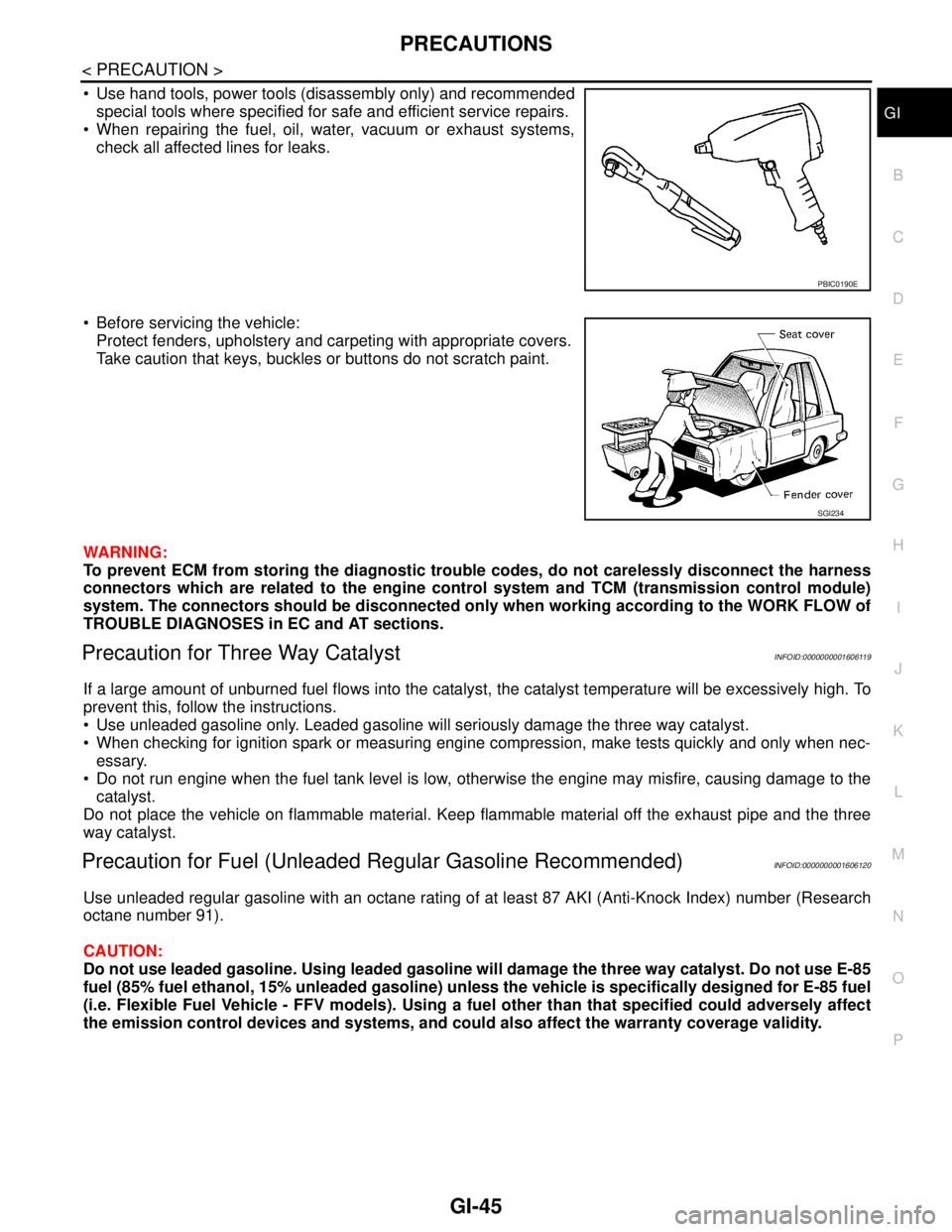
Use hand tools, power tools (disassembly only) and recommended
special tools where specified for safe and efficient service repairs.
When repairing the fuel, oil, water, vacuum or exhaust systems,
check all affected lines for leaks.
Before servicing the vehicle:
Protect fenders, upholstery and carpeting with appropriate covers.
Take caution that keys, buckles or buttons do not scratch paint.
WARNING:
To prevent ECM from storing the diagnostic trouble codes, do not carelessly disconnect the harness
connectors which are related to the engine control system and TCM (transmission control module)
system. The connectors should be disconnected only when working according to the WORK FLOW of
TROUBLE DIAGNOSES in EC and AT sections.
Precaution for Three Way CatalystINFOID:0000000001606119
If a large amount of unburned fuel flows into the catalyst, the catalyst temperature will be excessively high. To
prevent this, follow the instructions.
Use unleaded gasoline only. Leaded gasoline will seriously damage the three way catalyst.
When checking for ignition spark or measuring engine compression, make tests quickly and only when nec-
essary.
Do not run engine when the fuel tank level is low, otherwise the engine may misfire, causing damage to the
catalyst.
Do not place the vehicle on flammable material. Keep flammable material off the exhaust pipe and the three
way catalyst.
Precaution for Fuel (Unleaded Regular Gasoline Recommended)INFOID:0000000001606120
Use unleaded regular gasoline with an octane rating of at least 87 AKI (Anti-Knock Index) number (Research
octane number 91).
CAUTION:
Do not use leaded gasoline. Using leaded gasoline will damage the three way catalyst. Do not use E-85
fuel (85% fuel ethanol, 15% unleaded gasoline) unless the vehicle is specifically designed for E-85 fuel
(i.e. Flexible Fuel Vehicle - FFV models). Using a fuel other than that specified could adversely affect
the emission control devices and systems, and could also affect the warranty coverage validity.
PBIC0190E
SGI234
Page 3246 of 5883
GI-52
< BASIC INSPECTION >
SERVICE INFORMATION FOR ELECTRICAL INCIDENT
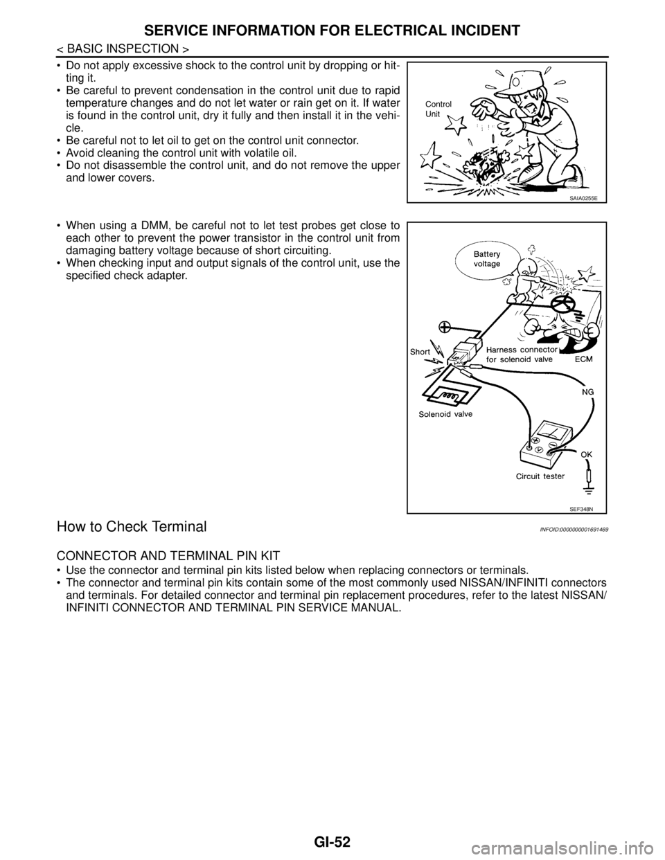
Do not apply excessive shock to the control unit by dropping or hit-
ting it.
Be careful to prevent condensation in the control unit due to rapid
temperature changes and do not let water or rain get on it. If water
is found in the control unit, dry it fully and then install it in the vehi-
cle.
Be careful not to let oil to get on the control unit connector.
Avoid cleaning the control unit with volatile oil.
Do not disassemble the control unit, and do not remove the upper
and lower covers.
When using a DMM, be careful not to let test probes get close to
each other to prevent the power transistor in the control unit from
damaging battery voltage because of short circuiting.
When checking input and output signals of the control unit, use the
specified check adapter.
How to Check TerminalINFOID:0000000001691469
CONNECTOR AND TERMINAL PIN KIT
Use the connector and terminal pin kits listed below when replacing connectors or terminals.
The connector and terminal pin kits contain some of the most commonly used NISSAN/INFINITI connectors
and terminals. For detailed connector and terminal pin replacement procedures, refer to the latest NISSAN/
INFINITI CONNECTOR AND TERMINAL PIN SERVICE MANUAL.
SAIA0255E
SEF348N
Page 3283 of 5883

HA-1
VENTILATION, HEATER & AIR CONDITIONER
C
D
E
F
G
H
J
K
L
M
SECTION HA
A
B
HA
N
O
P
CONTENTS
HEATER & AIR CONDITIONING SYSTEM
PRECAUTION ...............................................3
PRECAUTIONS ...................................................3
Precaution for Supplemental Restraint System
(SRS) "AIR BAG" and "SEAT BELT PRE-TEN-
SIONER" ...................................................................
3
Precaution for Procedure without Cowl Top Cover ......3
Precaution for Working with HFC-134a (R-134a) ......3
General Refrigerant Precaution ................................4
Oil Precaution ............................................................4
Precaution for Refrigerant Connection ......................4
Precaution for Service of Compressor ......................8
Precaution for Service Equipment .............................9
Precaution for Leak Detection Dye .........................10
PREPARATION ...........................................12
PREPARATION ..................................................12
HFC-134a (R-134a) Service Tool and Equipment ....12
Commercial Service Tool ........................................14
FUNCTION DIAGNOSIS ..............................16
REFRIGERATION SYSTEM ..............................16
Refrigerant Cycle ....................................................16
Refrigerant System Protection ................................16
OIL ......................................................................18
Maintenance of Oil Quantity in Compressor ...........18
ON-VEHICLE MAINTENANCE ....................19
OIL ......................................................................19
Maintenance of Oil Quantity in Compressor ...........19
REFRIGERATION SYSTEM ..............................21
HFC-134a (R-134a) Service Procedure ..................21
Checking of Refrigerant Leaks ................................22
FLUORESCENT LEAK DETECTOR .................24
Checking System for Leaks Using the Fluorescent
Leak Detector ..........................................................
24
Dye Injection ............................................................24
ELECTRICAL LEAK DETECTOR ....................25
Electronic Refrigerant Leak Detector .......................25
ON-VEHICLE REPAIR .................................27
REFRIGERATION SYSTEM .............................27
Component ..............................................................27
HFC-134a (R-134a) Service Procedure ..................29
COMPRESSOR .................................................32
Removal and Installation of Compressor -
MR18DE ..................................................................
32
Removal and Installation of Compressor -
HR16DE ..................................................................
34
Removal and Installation of Compressor - K9K .......35
LOW-PRESSURE FLEXIBLE HOSE ................38
Removal and Installation of Low-Pressure Flexi-
ble Hose - MR18DE, HR16DE ................................
38
Removal and Installation of Low-Pressure Flexi-
ble Hose - K9K ........................................................
38
LOW-PRESSURE PIPE ....................................40
Removal and Installation of Low-Pressure Pipe -
K9K ..........................................................................
40
HIGH-PRESSURE FLEXIBLE HOSE ...............41
Removal and Installation of High-Pressure Flexi-
ble Hose - MR18DE, HR16DE ................................
41
Removal and Installation of High-Pressure Flexi-
ble Hose - K9K ........................................................
41
HIGH-PRESSURE PIPE ....................................43
Removal and Installation of High-Pressure Pipe -
MR18DE, HR16DE ..................................................
43
Removal and Installation of High-Pressure Pipe -
K9K ..........................................................................
43
CONDENSER ....................................................45
Removal and Installation of Condenser -
MR18DE, HR16DE ..................................................
45
Page 3304 of 5883
HA-22
< ON-VEHICLE MAINTENANCE >
REFRIGERATION SYSTEM
Checking of Refrigerant Leaks
INFOID:0000000001396447
Perform a visual inspection of all refrigeration parts, fittings, hoses and components for signs of A/C oil leak-
age, damage and corrosion. A/C oil leakage may indicate an area of refrigerant leakage. Allow extra inspec-
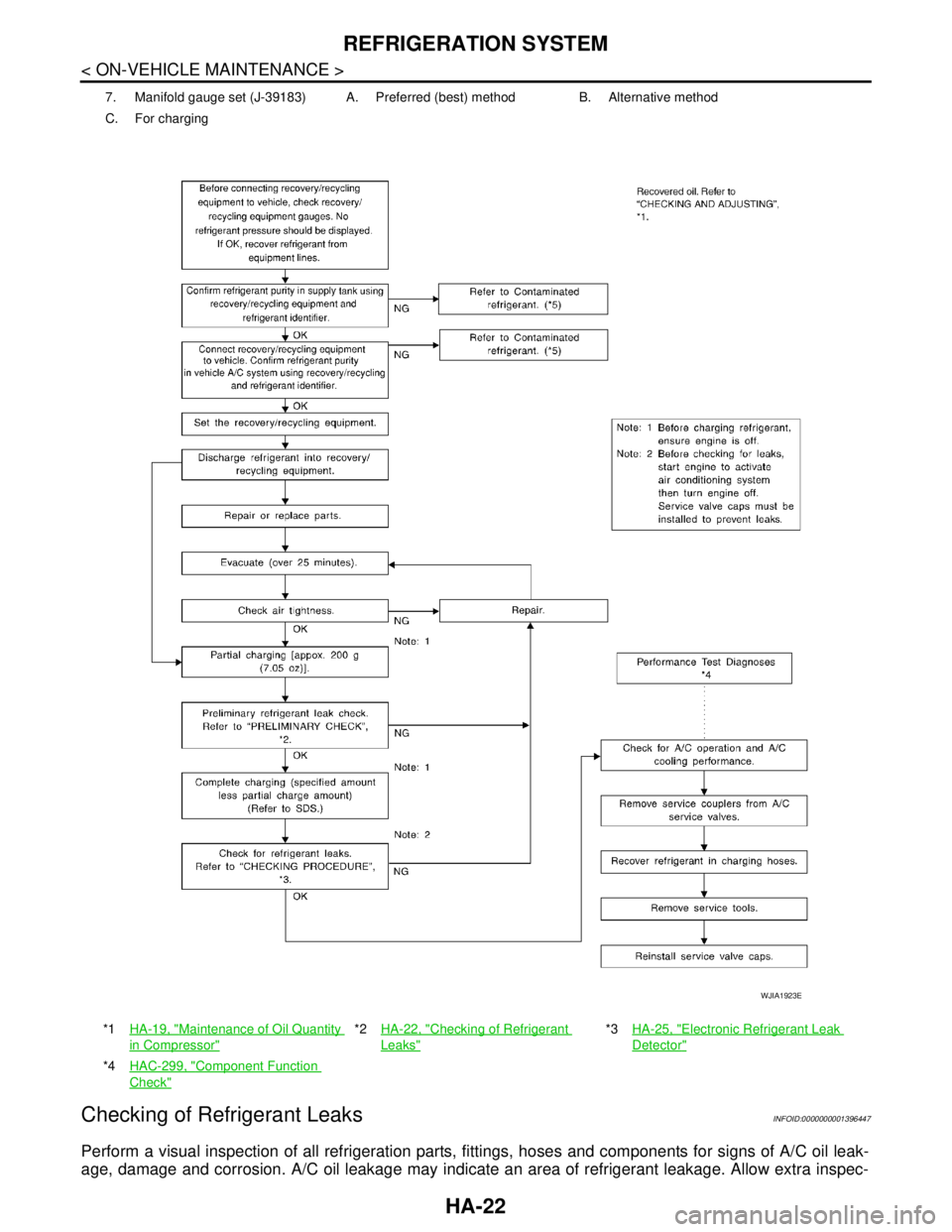
7. Manifold gauge set (J-39183) A. Preferred (best) method B. Alternative method
C. For charging
*1HA-19, "
Maintenance of Oil Quantity
in Compressor"
*2HA-22, "Checking of Refrigerant
Leaks"
*3HA-25, "Electronic Refrigerant Leak
Detector"
*4HAC-299, "Component Function
Check"
WJIA1923E
Page 3306 of 5883

HA-24
< ON-VEHICLE MAINTENANCE >
FLUORESCENT LEAK DETECTOR
FLUORESCENT LEAK DETECTOR
Checking System for Leaks Using the Fluorescent Leak DetectorINFOID:0000000001396445
1. Check A/C system for leaks using the UV lamp and safety goggles J-42220 in a low sunlight area (area
without windows preferable). Illuminate all components, fittings and lines. The dye will appear as a bright
green/yellow area at the point of leakage. Fluorescent dye observed at the evaporator drain opening indi-
cates an evaporator core assembly (tubes, core or expansion valve) leak.
2. If the suspected area is difficult to see, use an adjustable mirror or wipe the area with a clean shop rag or
cloth, with the UV lamp for dye residue.
3. After the leak is repaired, remove any residual dye using dye cleaner J-43872 to prevent future misdiag-
nosis.
4. Perform a system performance check and verify the leak repair with an approved electronic refrigerant
leak detector.
NOTE:
Other gases in the work area or substances on the A/C components, for example, anti-freeze, windshield
washer fluid, solvents and oils, may falsely trigger the leak detector. Make sure the surfaces to be checked are
clean.
Clean with a dry cloth or blow off with shop air.
Do not allow the sensor tip of the detector to contact with any substance. This can also cause false readings
and may damage the detector.
Dye InjectionINFOID:0000000001396446
(This procedure is only necessary when recharging the system or when the compressor has seized and was
replaced.)
1. Check A/C system static (at rest) pressure. Pressure must be at least 345 kPa (3.45 bar, 3.52 kg/cm
2, 50
psi).
2. Pour one bottle (1/4 ounce / 7.4 cc) of the A/C refrigerant dye into the injector tool J-41459.
3. Connect the injector tool to the A/C low-pressure side service fitting.
4. Start engine and switch A/C ON.
5. When the A/C operating (compressor running), inject one bottle (1/4 ounce / 7.4 cc) of fluorescent dye
through the low-pressure service valve using dye injector tool J-41459 (refer to the manufacture’s operat-
ing instructions).
6. With the engine still running, disconnect the injector tool from the service fitting.
CAUTION:
Be careful the A/C system or replacing a component, pour the dye directly into the open system
connection and proceed with the service procedures.
7. Operate the A/C system for a minimum of 20 minutes to mix the dye with the system oil. Depending on the
leak size, operating conditions and location of the leak, it may take from minutes to days for the dye to
penetrate a leak and become visible.
Page 3313 of 5883
REFRIGERATION SYSTEM
HA-31
< ON-VEHICLE REPAIR >
C
D
E
F
G
H
J
K
L
MA
B
HA
N
O
P
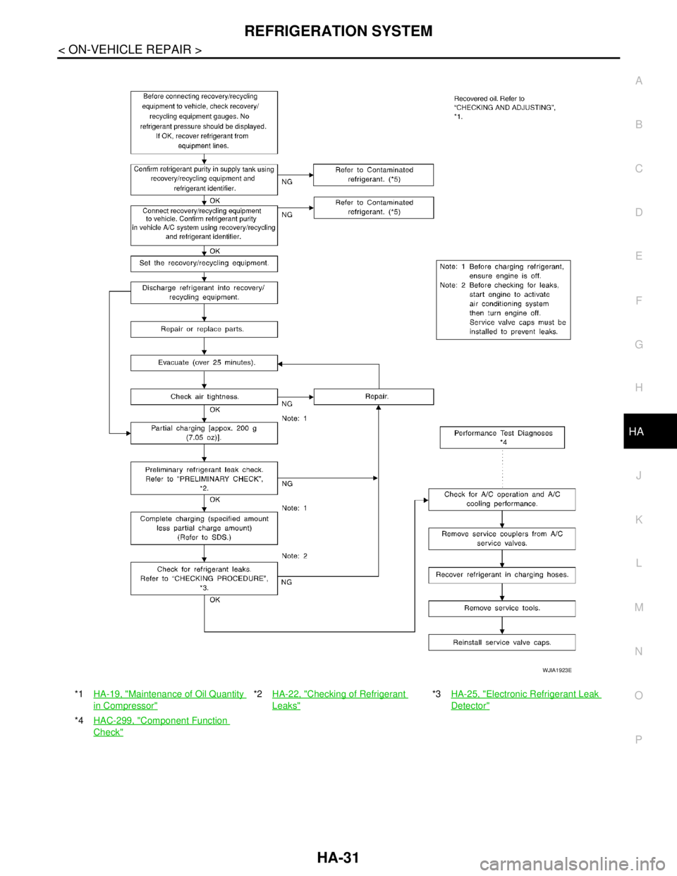
*1HA-19, "Maintenance of Oil Quantity
in Compressor"
*2HA-22, "Checking of Refrigerant
Leaks"
*3HA-25, "Electronic Refrigerant Leak
Detector"
*4HAC-299, "Component Function
Check"
WJIA1923E
Page 3315 of 5883
COMPRESSOR
HA-33
< ON-VEHICLE REPAIR >
C
D
E
F
G
H
J
K
L
MA
B
HA
N
O
P
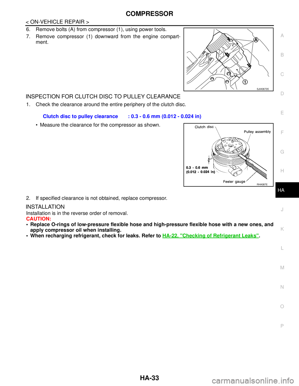
6. Remove bolts (A) from compressor (1), using power tools.
7. Remove compressor (1) downward from the engine compart-
ment.
INSPECTION FOR CLUTCH DISC TO PULLEY CLEARANCE
1. Check the clearance around the entire periphery of the clutch disc.
Measure the clearance for the compressor as shown.
2. If specified clearance is not obtained, replace compressor.
INSTALLATION
Installation is in the reverse order of removal.
CAUTION:
Replace O-rings of low-pressure flexible hose and high-pressure flexible hose with a new ones, and
apply compressor oil when installing.
When recharging refrigerant, check for leaks. Refer to HA-22, "
Checking of Refrigerant Leaks".
SJIA0672E
Clutch disc to pulley clearance : 0.3 - 0.6 mm (0.012 - 0.024 in)
RHA087E