2007 NISSAN TIIDA Body
[x] Cancel search: BodyPage 4416 of 5883

PCS-2
U1000 CAN COMM CIRCUIT ............................36
Description ..............................................................36
DTC Logic ...............................................................36
Diagnosis Procedure ..............................................36
POWER SUPPLY AND GROUND CIRCUIT .....37
BCM ...........................................................................37
BCM : Diagnosis Procedure ...................................37
BCM : Special Repair Requirement ........................37
IPDM E/R (INTELLIGENT POWER DISTRIBU-
TION MODULE ENGINE ROOM) .............................
37
IPDM E/R (INTELLIGENT POWER DISTRIBU-
TION MODULE ENGINE ROOM) : Diagnosis Pro-
cedure .....................................................................
37
ECU DIAGNOSIS ........................................38
BCM (BODY CONTROL MODULE) ..................38
Reference Value .....................................................38
Terminal Layout ......................................................38
Physical Values ......................................................38
Wiring Diagram .......................................................38
DTC Inspection Priority Chart ...............................38
DTC Index ..............................................................38
IPDM E/R (INTELLIGENT POWER DISTRI-
BUTION MODULE ENGINE ROOM) .................
39
Reference Value .....................................................39
Terminal Layout ......................................................39
Physical Values .......................................................39
Wiring Diagram .......................................................39
Fail Safe .................................................................39
DTC Index ..............................................................39
ON-VEHICLE MAINTENANCE ..................40
PRE-INSPECTION FOR DIAGNOSTIC ............40
Basic Inspection ......................................................40
ON-VEHICLE REPAIR ...............................41
BCM (BODY CONTROL MODULE) ..................41
Removal and Installation .........................................41
Page 4452 of 5883
![NISSAN TIIDA 2007 Service Repair Manual PCS-38
< ECU DIAGNOSIS >[POWER DISTRIBUTION SYSTEM]
BCM (BODY CONTROL MODULE)
ECU DIAGNOSIS
BCM (BODY CONTROL MODULE)
Reference ValueINFOID:0000000001697616
Refer to BCS-35, "Reference Value".
Termina NISSAN TIIDA 2007 Service Repair Manual PCS-38
< ECU DIAGNOSIS >[POWER DISTRIBUTION SYSTEM]
BCM (BODY CONTROL MODULE)
ECU DIAGNOSIS
BCM (BODY CONTROL MODULE)
Reference ValueINFOID:0000000001697616
Refer to BCS-35, "Reference Value".
Termina](/manual-img/5/57395/w960_57395-4451.png)
PCS-38
< ECU DIAGNOSIS >[POWER DISTRIBUTION SYSTEM]
BCM (BODY CONTROL MODULE)
ECU DIAGNOSIS
BCM (BODY CONTROL MODULE)
Reference ValueINFOID:0000000001697616
Refer to BCS-35, "Reference Value".
Terminal LayoutINFOID:0000000001697617
Refer to BCS-38, "Terminal Layout".
Physical ValuesINFOID:0000000001697618
Refer to BCS-39, "Physical Values".
Wiring DiagramINFOID:0000000001697619
Refer to BCS-50, "Wiring Diagram".
DTC Inspection Priority ChartINFOID:0000000001697620
Refer to BCS-53, "DTCInspectionPriorityChart".
DTC IndexINFOID:0000000001697621
Refer to BCS-54, "DTCIndex".
Page 4455 of 5883
![NISSAN TIIDA 2007 Service Repair Manual PCS
BCM (BODY CONTROL MODULE)
PCS-41
< ON-VEHICLE REPAIR >[POWER DISTRIBUTION SYSTEM]
C
D
E
F
G
H
I
J
K
L B A
O
P N
ON-VEHICLE REPAIR
BCM (BODY CONTROL MODULE)
Removal and InstallationINFOID:000000000 NISSAN TIIDA 2007 Service Repair Manual PCS
BCM (BODY CONTROL MODULE)
PCS-41
< ON-VEHICLE REPAIR >[POWER DISTRIBUTION SYSTEM]
C
D
E
F
G
H
I
J
K
L B A
O
P N
ON-VEHICLE REPAIR
BCM (BODY CONTROL MODULE)
Removal and InstallationINFOID:000000000](/manual-img/5/57395/w960_57395-4454.png)
PCS
BCM (BODY CONTROL MODULE)
PCS-41
< ON-VEHICLE REPAIR >[POWER DISTRIBUTION SYSTEM]
C
D
E
F
G
H
I
J
K
L B A
O
P N
ON-VEHICLE REPAIR
BCM (BODY CONTROL MODULE)
Removal and InstallationINFOID:0000000001697629
Refer to BCS-57, "Removal and Installation of BCM".
Page 4462 of 5883

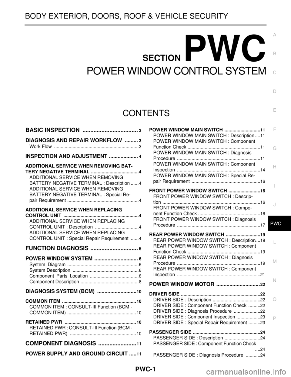
PWC-1
BODY EXTERIOR, DOORS, ROOF & VEHICLE SECURITY
C
D
E
F
G
H
I
J
L
M
SECTION PWC
A
B
PWC
N
O
P
CONTENTS
POWER WINDOW CONTROL SYSTEM
BASIC INSPECTION ....................................3
DIAGNOSIS AND REPAIR WORKFLOW ..........3
Work Flow .................................................................3
INSPECTION AND ADJUSTMENT .....................4
ADDITIONAL SERVICE WHEN REMOVING BAT-
TERY NEGATIVE TERMINAL .....................................
4
ADDITIONAL SERVICE WHEN REMOVING
BATTERY NEGATIVE TERMINAL : Description ......
4
ADDITIONAL SERVICE WHEN REMOVING
BATTERY NEGATIVE TERMINAL : Special Re-
pair Requirement .......................................................
4
ADDITIONAL SERVICE WHEN REPLACING
CONTROL UNIT ..........................................................
4
ADDITIONAL SERVICE WHEN REPLACING
CONTROL UNIT : Description ..................................
4
ADDITIONAL SERVICE WHEN REPLACING
CONTROL UNIT : Special Repair Requirement .......
4
FUNCTION DIAGNOSIS ...............................6
POWER WINDOW SYSTEM ...............................6
System Diagram .......................................................6
System Description ...................................................6
Component Parts Location ......................................8
Component Description .............................................8
DIAGNOSIS SYSTEM (BCM) ............................10
COMMON ITEM .........................................................10
COMMON ITEM : CONSULT-III Function (BCM -
COMMON ITEM) .....................................................
10
RETAINED PWR .......................................................10
RETAINED PWR : CONSULT-III Function (BCM -
RETAINED PWR) ...................................................
10
COMPONENT DIAGNOSIS .........................11
POWER SUPPLY AND GROUND CIRCUIT ......11
POWER WINDOW MAIN SWITCH ............................11
POWER WINDOW MAIN SWITCH : Description ....11
POWER WINDOW MAIN SWITCH : Component
Function Check ........................................................
11
POWER WINDOW MAIN SWITCH : Diagnosis
Procedure ................................................................
11
POWER WINDOW MAIN SWITCH : Component
Inspection ................................................................
14
POWER WINDOW MAIN SWITCH : Special Re-
pair Requirement .....................................................
16
FRONT POWER WINDOW SWITCH .........................16
FRONT POWER WINDOW SWITCH : Descrip-
tion ...........................................................................
16
FRONT POWER WINDOW SWITCH : Compo-
nent Function Check ................................................
16
FRONT POWER WINDOW SWITCH : Diagnosis
Procedure ................................................................
17
REAR POWER WINDOW SWITCH ...........................19
REAR POWER WINDOW SWITCH : Description ....19
REAR POWER WINDOW SWITCH : Component
Function Check ........................................................
19
REAR POWER WINDOW SWITCH : Diagnosis
Procedure ................................................................
19
REAR POWER WINDOW SWITCH : Component
Inspection ................................................................
21
POWER WINDOW MOTOR ..............................22
DRIVER SIDE .............................................................22
DRIVER SIDE : Description .....................................22
DRIVER SIDE : Component Function Check ..........22
DRIVER SIDE : Diagnosis Procedure .....................22
DRIVER SIDE : Component Inspection ...................23
DRIVER SIDE : Special Repair Requirement ..........23
PASSENGER SIDE ....................................................24
PASSENGER SIDE : Description ............................24
PASSENGER SIDE : Component Function Check
....
24
PASSENGER SIDE : Diagnosis Procedure ............24
Page 4463 of 5883

PWC-2
PASSENGER SIDE : Component Inspection .........25
REAR LH ...................................................................25
REAR LH : Description ...........................................25
REAR LH : Component Function Check ................25
REAR LH : Diagnosis Procedure ............................25
REAR LH : Component Inspection .........................26
REAR RH ..................................................................27
REAR RH : Description ..........................................27
REAR RH : Component Function Check ................27
REAR RH : Diagnosis Procedure ...........................27
REAR RH : Component Inspection ........................28
ENCODER .........................................................29
DRIVER SIDE ............................................................29
DRIVER SIDE : Description ....................................29
DRIVER SIDE : Component Function Check .........29
DRIVER SIDE : Diagnosis Procedure ....................29
DRIVER SIDE : Special Repair Requirement .........31
DOOR SWITCH .................................................32
Description ..............................................................32
Component Function Check ...................................32
Diagnosis Procedure ..............................................32
Component Inspection ............................................33
POWER WINDOW LOCK SWITCH ...................34
Description ..............................................................34
Component Function Check ...................................34
Special Repair Requirement ...................................34
ECU DIAGNOSIS ........................................35
BCM (BODY CONTROL MODULE) ..................35
Reference Value .....................................................35
POWER WINDOW MAIN SWITCH ....................36
Reference Value .....................................................36
Wiring Diagram - LHD - ..........................................38
Wiring Diagram - RHD - ..........................................45
Fail Safe .................................................................51
SYMPTOM DIAGNOSIS ............................53
NONE OF THE POWER WINDOWS CAN BE
OPERATED USING ANY SWITCH ...................
53
Diagnosis Procedure ...............................................53
DRIVER SIDE POWER WINDOW ALONE
DOES NOT OPERATE ......................................
54
Diagnosis Procedure ...............................................54
FRONT PASSENGER SIDE POWER WIN-
DOW ALONE DOES NOT OPERATE ...............
55
Diagnosis Procedure ...............................................55
REAR LH SIDE POWER WINDOW ALONE
DOES NOT OPERATE ......................................
56
Diagnosis Procedure ...............................................56
REAR RH SIDE POWER WINDOW ALONE
DOES NOT OPERATE ......................................
57
Diagnosis Procedure ...............................................57
ANTI-PINCH SYSTEM DOES NOT OPERATE
NORMALLY (DRIVER SIDE) ............................
58
Diagnosis Procedure ...............................................58
AUTO OPERATION DOES NOT OPERATE
BUT MANUAL OPERATE NORMALLY
(DRIVER SIDE) ..................................................
59
Diagnosis Procedure ...............................................59
POWER WINDOW RETAINED POWER OP-
ERATION DOES NOT OPERATE PROPERLY
...
60
Diagnosis Procedure ...............................................60
POWER WINDOW LOCK SWITCH DOES
NOT FUNCTION ................................................
61
Diagnosis Procedure ...............................................61
ON-VEHICLE MAINTENANCE ..................62
PRE-INSPECTION FOR DIAGNOSTIC ............62
Basic Inspection ......................................................62
Page 4465 of 5883

PWC-4
< BASIC INSPECTION >
INSPECTION AND ADJUSTMENT
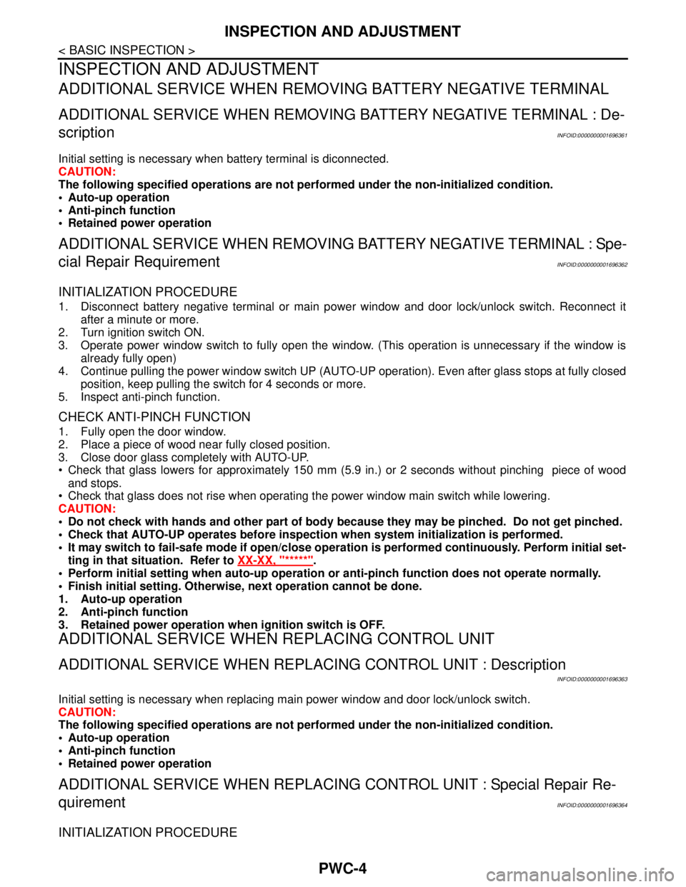
INSPECTION AND ADJUSTMENT
ADDITIONAL SERVICE WHEN REMOVING BATTERY NEGATIVE TERMINAL
ADDITIONAL SERVICE WHEN REMOVING BATTERY NEGATIVE TERMINAL : De-
scription
INFOID:0000000001696361
Initial setting is necessary when battery terminal is diconnected.
CAUTION:
The following specified operations are not performed under the non-initialized condition.
• Auto-up operation
Anti-pinch function
Retained power operation
ADDITIONAL SERVICE WHEN REMOVING BATTERY NEGATIVE TERMINAL : Spe-
cial Repair Requirement
INFOID:0000000001696362
INITIALIZATION PROCEDURE
1. Disconnect battery negative terminal or main power window and door lock/unlock switch. Reconnect it
after a minute or more.
2. Turn ignition switch ON.
3. Operate power window switch to fully open the window. (This operation is unnecessary if the window is
already fully open)
4. Continue pulling the power window switch UP (AUTO-UP operation). Even after glass stops at fully closed
position, keep pulling the switch for 4 seconds or more.
5. Inspect anti-pinch function.
CHECK ANTI-PINCH FUNCTION
1. Fully open the door window.
2. Place a piece of wood near fully closed position.
3. Close door glass completely with AUTO-UP.
Check that glass lowers for approximately 150 mm (5.9 in.) or 2 seconds without pinching piece of wood
and stops.
Check that glass does not rise when operating the power window main switch while lowering.
CAUTION:
Do not check with hands and other part of body because they may be pinched. Do not get pinched.
Check that AUTO-UP operates before inspection when system initialization is performed.
It may switch to fail-safe mode if open/close operation is performed continuously. Perform initial set-
ting in that situation. Refer to XX-XX, "*****"
.
Perform initial setting when auto-up operation or anti-pinch function does not operate normally.
Finish initial setting. Otherwise, next operation cannot be done.
1. Auto-up operation
2. Anti-pinch function
3. Retained power operation when ignition switch is OFF.
ADDITIONAL SERVICE WHEN REPLACING CONTROL UNIT
ADDITIONAL SERVICE WHEN REPLACING CONTROL UNIT : Description
INFOID:0000000001696363
Initial setting is necessary when replacing main power window and door lock/unlock switch.
CAUTION:
The following specified operations are not performed under the non-initialized condition.
Auto-up operation
Anti-pinch function
Retained power operation
ADDITIONAL SERVICE WHEN REPLACING CONTROL UNIT : Special Repair Re-
quirement
INFOID:0000000001696364
INITIALIZATION PROCEDURE
Page 4466 of 5883

INSPECTION AND ADJUSTMENT
PWC-5
< BASIC INSPECTION >
C
D
E
F
G
H
I
J
L
MA
B
PWC
N
O
P
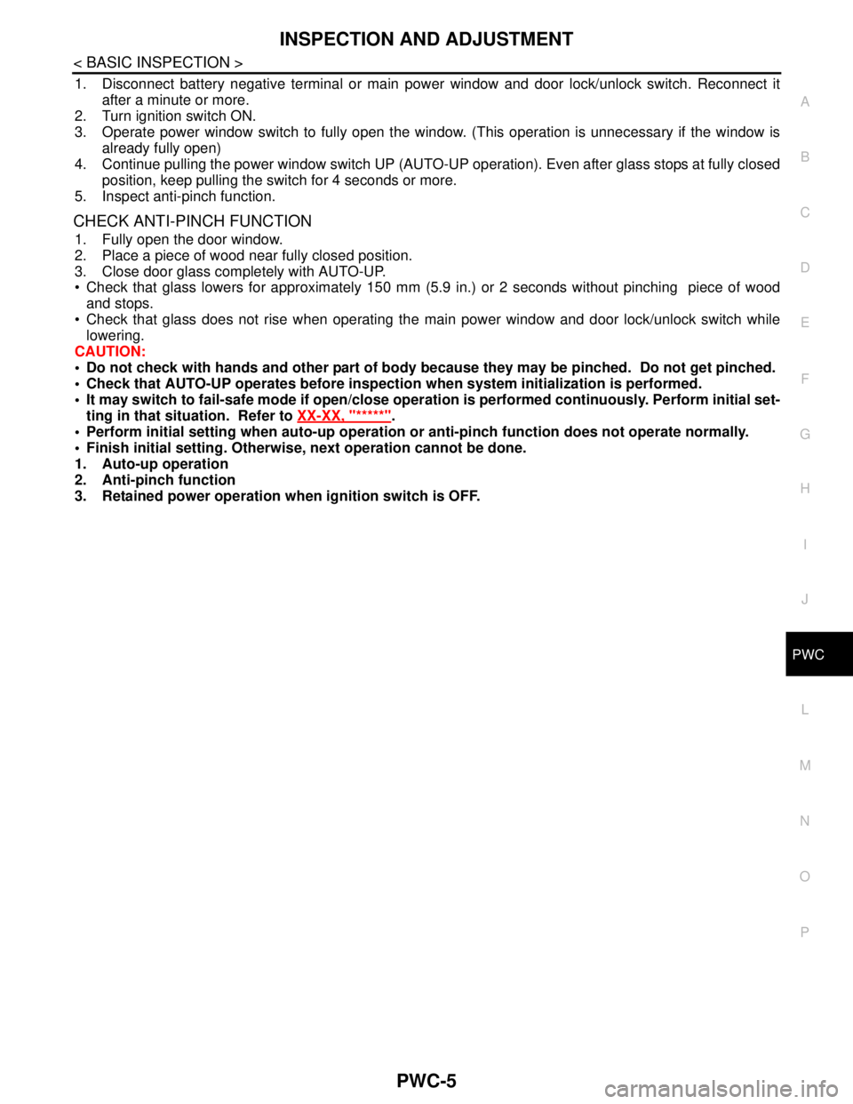
1. Disconnect battery negative terminal or main power window and door lock/unlock switch. Reconnect it
after a minute or more.
2. Turn ignition switch ON.
3. Operate power window switch to fully open the window. (This operation is unnecessary if the window is
already fully open)
4. Continue pulling the power window switch UP (AUTO-UP operation). Even after glass stops at fully closed
position, keep pulling the switch for 4 seconds or more.
5. Inspect anti-pinch function.
CHECK ANTI-PINCH FUNCTION
1. Fully open the door window.
2. Place a piece of wood near fully closed position.
3. Close door glass completely with AUTO-UP.
Check that glass lowers for approximately 150 mm (5.9 in.) or 2 seconds without pinching piece of wood
and stops.
Check that glass does not rise when operating the main power window and door lock/unlock switch while
lowering.
CAUTION:
Do not check with hands and other part of body because they may be pinched. Do not get pinched.
Check that AUTO-UP operates before inspection when system initialization is performed.
It may switch to fail-safe mode if open/close operation is performed continuously. Perform initial set-
ting in that situation. Refer to XX-XX, "*****"
.
Perform initial setting when auto-up operation or anti-pinch function does not operate normally.
Finish initial setting. Otherwise, next operation cannot be done.
1. Auto-up operation
2. Anti-pinch function
3. Retained power operation when ignition switch is OFF.
Page 4496 of 5883

BCM (BODY CONTROL MODULE)
PWC-35
< ECU DIAGNOSIS >
C
D
E
F
G
H
I
J
L
MA
B
PWC
N
O
P
ECU DIAGNOSIS
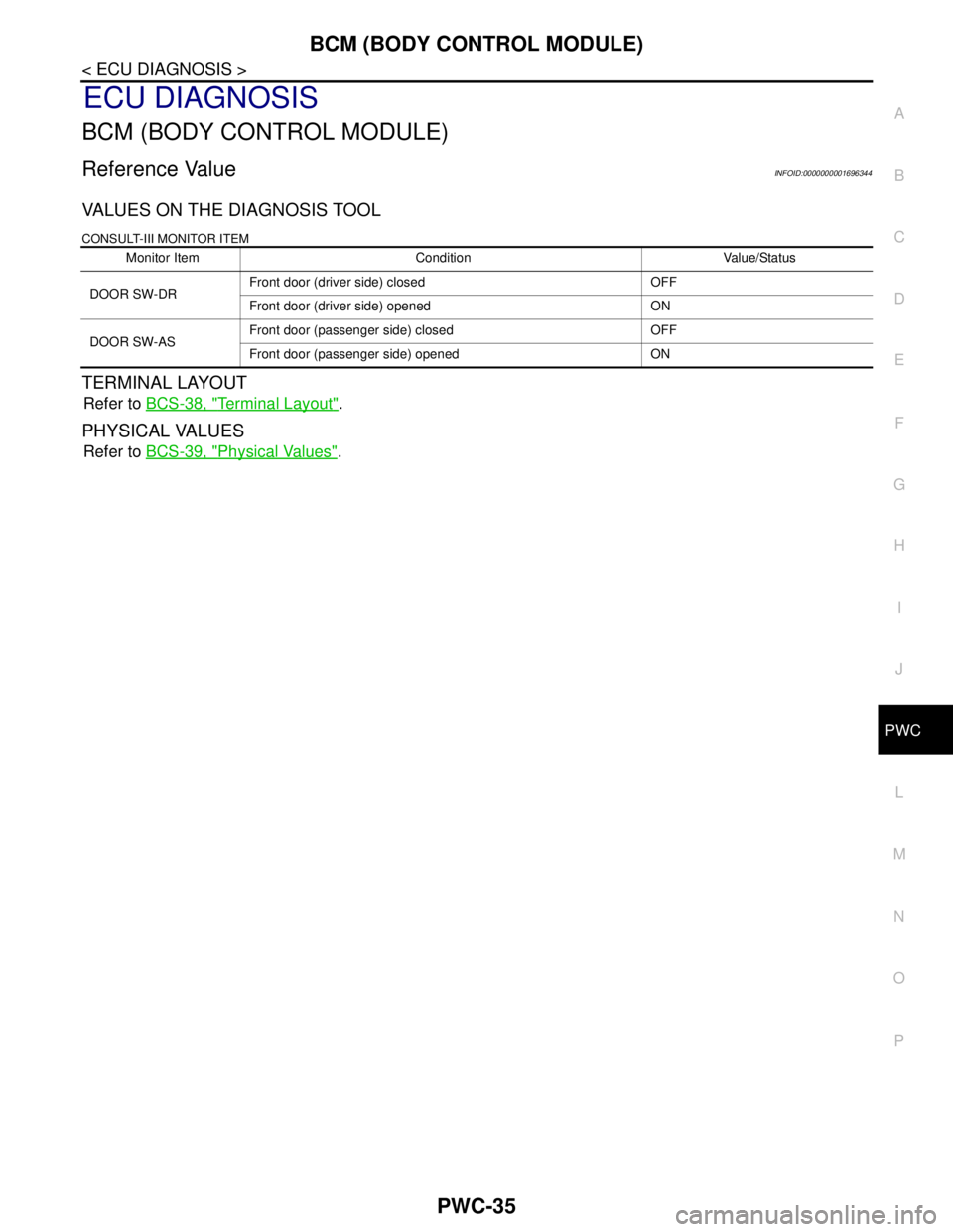
BCM (BODY CONTROL MODULE)
Reference ValueINFOID:0000000001696344
VALUES ON THE DIAGNOSIS TOOL
CONSULT-III MONITOR ITEM
TERMINAL LAYOUT
Refer to BCS-38, "Terminal Layout".
PHYSICAL VALUES
Refer to BCS-39, "Physical Values".
Monitor Item Condition Value/Status
DOOR SW-DRFront door (driver side) closed OFF
Front door (driver side) opened ON
DOOR SW-ASFront door (passenger side) closed OFF
Front door (passenger side) opened ON