2007 NISSAN TIIDA Body
[x] Cancel search: BodyPage 4306 of 5883
MIR-8
< REMOVAL AND INSTALLATION >
DOOR MIRROR
Disassembly and Assembly
INFOID:0000000001716809
DISASSEMBLY
1. Pull out all the terminals from the connector.
NOTE:
Before pulling out the terminal, note the connector terminal arrangement.
2. Turn the mirror glass surface upward.
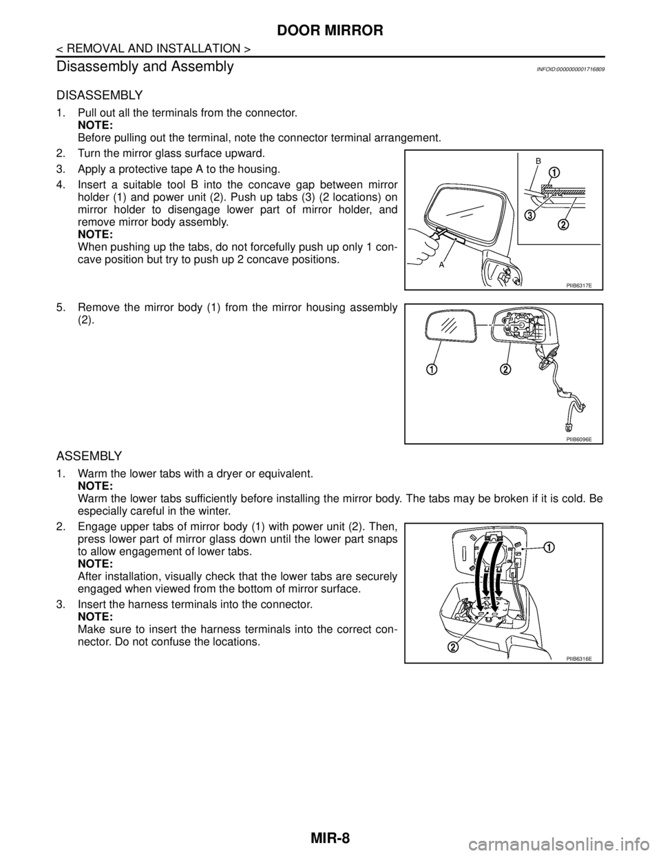
3. Apply a protective tape A to the housing.
4. Insert a suitable tool B into the concave gap between mirror
holder (1) and power unit (2). Push up tabs (3) (2 locations) on
mirror holder to disengage lower part of mirror holder, and
remove mirror body assembly.
NOTE:
When pushing up the tabs, do not forcefully push up only 1 con-
cave position but try to push up 2 concave positions.
5. Remove the mirror body (1) from the mirror housing assembly
(2).
ASSEMBLY
1. Warm the lower tabs with a dryer or equivalent.
NOTE:
Warm the lower tabs sufficiently before installing the mirror body. The tabs may be broken if it is cold. Be
especially careful in the winter.
2. Engage upper tabs of mirror body (1) with power unit (2). Then,
press lower part of mirror glass down until the lower part snaps
to allow engagement of lower tabs.
NOTE:
After installation, visually check that the lower tabs are securely
engaged when viewed from the bottom of mirror surface.
3. Insert the harness terminals into the connector.
NOTE:
Make sure to insert the harness terminals into the correct con-
nector. Do not confuse the locations.
PIIB6317E
PIIB6096E
PIIB6316E
Page 4308 of 5883
MWI
MWI-1
DRIVER INFORMATION & MULTIMEDIA
C
D
E
F
G
H
I
J
K
L
MB
SECTION MWI
A
O
P
CONTENTS
METER, WARNING LAMP & INDICATOR
BASIC INSPECTION ....................................3
DIAGNOSIS AND REPAIR WORKFLOW ..........3
Work Flow .................................................................3
FUNCTION DIAGNOSIS ...............................4
METER SYSTEM .................................................4
METER SYSTEM .........................................................4
METER SYSTEM : System Diagram ........................4
METER SYSTEM : System Description ....................4
METER SYSTEM : Arrangement of Combination
Meter .........................................................................
5
METER SYSTEM : Component Parts Location ........6
METER SYSTEM : Component Description .............7
SPEEDOMETER ..........................................................7
SPEEDOMETER : System Diagram .........................7
SPEEDOMETER : System Description .....................7
SPEEDOMETER : Component Parts Location .........8
SPEEDOMETER : Component Description ..............9
TACHOMETER ............................................................9
TACHOMETER : System Diagram ...........................9
TACHOMETER : System Description .......................9
TACHOMETER : Component Parts Location .........10
TACHOMETER : Component Description ..............11
FUEL GAUGE ............................................................11
FUEL GAUGE : System Diagram ...........................11
FUEL GAUGE : System Description .......................11
FUEL GAUGE : Component Parts Location ...........12
FUEL GAUGE : Component Description ................13
ODO/TRIP METER ....................................................13
ODO/TRIP METER : System Diagram ....................13
ODO/TRIP METER : System Description ...............13
ODO/TRIP METER : Component Parts Location ....14
ODO/TRIP METER : Component Description .........15
WARNING LAMPS/INDICATOR LAMPS ..................15
WARNING LAMPS/INDICATOR LAMPS : System
Diagram ...................................................................
15
WARNING LAMPS/INDICATOR LAMPS : System
Description ...............................................................
15
WARNING LAMPS/INDICATOR LAMPS : Com-
ponent Parts Location ..............................................
16
WARNING LAMPS/INDICATOR LAMPS : Com-
ponent Description ...................................................
17
INFORMATION DISPLAY ..........................................17
INFORMATION DISPLAY : System Diagram ..........17
INFORMATION DISPLAY : System Description .....17
INFORMATION DISPLAY : Component Parts Lo-
cation .......................................................................
19
INFORMATION DISPLAY : Component Descrip-
tion ...........................................................................
19
DIAGNOSIS SYSTEM (METER) .......................21
Diagnosis Description ..............................................21
CONSULT-III Function (METER/M&A) ....................22
COMPONENT DIAGNOSIS .........................24
DTC U1000 CAN COMMUNICATION ...............24
DTC Logic ................................................................24
Diagnosis Procedure ..............................................24
DTC B2205 VEHICLE SPEED CIRCUIT ..........25
Description ...............................................................25
DTC Logic ................................................................25
Diagnosis Procedure ..............................................25
POWER SUPPLY AND GROUND CIRCUIT ....26
COMBINATION METER ............................................26
COMBINATION METER : Diagnosis Procedure .....26
BCM (BODY CONTROL MODULE) ..........................26
BCM (BODY CONTROL MODULE) : Diagnosis
Procedure ................................................................
26
IPDM E/R (INTELLIGENT POWER DISTRIBU-
TION MODULE ENGINE ROOM) ..........................
Page 4309 of 5883

MWI-2
IPDM E/R (INTELLIGENT POWER DISTRIBU-
TION MODULE ENGINE ROOM) : Diagnosis Pro-
cedure .....................................................................
27
FUEL LEVEL SENSOR SIGNAL CIRCUIT .......29
Description ..............................................................29
Component Function Check ...................................29
Diagnosis Procedure .............................................29
Component Inspection ............................................30
OIL PRESSURE SWITCH SIGNAL CIRCUIT ...31
Description ..............................................................31
Component Function Check ...................................31
Diagnosis Procedure ..............................................31
Component Inspection ............................................31
OIL LEVEL SENSOR SIGNAL CIRCUIT ..........32
Description ..............................................................32
Diagnosis Procedure (With Diesel) .........................32
Diagnosis Procedure (Without Diesel) ....................32
Component Inspection (With Diesel) ......................32
Component Inspection (Without Diesel) .................33
AMBIENT SENSOR SIGNAL CIRCUIT .............34
Description ..............................................................34
Diagnosis Procedure ..............................................34
Component Inspection ............................................35
ECU DIAGNOSIS ........................................36
COMBINATION METER ....................................36
Reference Value .....................................................36
Wiring Diagram .......................................................39
Fail Safe .................................................................53
DTC Index ..............................................................54
BCM (BODY CONTROL MODULE) ..................55
Reference Value .....................................................55
Terminal Layout ......................................................58
Physical Values ......................................................58
Wiring Diagram .......................................................70
DTC Inspection Priority Chart ..............................73
DTC Index ..............................................................74
IPDM E/R (INTELLIGENT POWER DISTRI-
BUTION MODULE ENGINE ROOM) .................
75
Reference Value .....................................................75
Terminal Layout ......................................................77
Physical Values ......................................................77
Wiring Diagram .......................................................81
Fail Safe .................................................................84
DTC Index ..............................................................86
SYMPTOM DIAGNOSIS ............................87
THE FUEL GAUGE POINTER DOES NOT
MOVE .................................................................
87
Description ..............................................................87
Diagnosis Procedure ...............................................87
THE FUEL GAUGE POINTER DOES NOT
MOVE TO "F" WHEN REFUELING ..................
88
Description ..............................................................88
Diagnosis Procedure ...............................................88
THE OIL PRESSURE WARNING LAMP
DOES NOT TURN ON .......................................
89
Description ..............................................................89
Diagnosis Procedure ...............................................89
THE OIL PRESSURE WARNING LAMP
DOES NOT TURN OFF .....................................
90
Description ..............................................................90
Diagnosis Procedure ...............................................90
THE AMBIENT TEMPERATURE DISPLAY IS
INCORRECT ......................................................
91
Description ..............................................................91
Diagnosis Procedure ...............................................91
NORMAL OPERATING CONDITION ................92
INFORMATION DISPLAY .........................................92
INFORMATION DISPLAY : Description ..................92
PRECAUTION ............................................93
PRECAUTIONS .................................................93
Supplemental Restraint System (SRS) "AIR BAG"
and "SEAT BELT PRE-TENSIONER" ....................
93
ON-VEHICLE REPAIR ...............................94
COMBINATION METER ....................................94
Removal and Installation .........................................94
DISASSEMBLY AND ASSEMBLY ............97
COMBINATION METER ....................................97
Disassembly and Assembly ....................................97
Page 4333 of 5883
MWI-26
< COMPONENT DIAGNOSIS >
POWER SUPPLY AND GROUND CIRCUIT
POWER SUPPLY AND GROUND CIRCUIT
COMBINATION METER
COMBINATION METER : Diagnosis ProcedureINFOID:0000000001374688
1.CHECK FUSES
Check for blown combination meter fuses.
Is the inspection result normal?
YES >> GO TO 2
NO >> If fuse is blown, be sure to eliminate cause of malfunction before installing new fuse.
2.POWER SUPPLY CIRCUIT CHECK
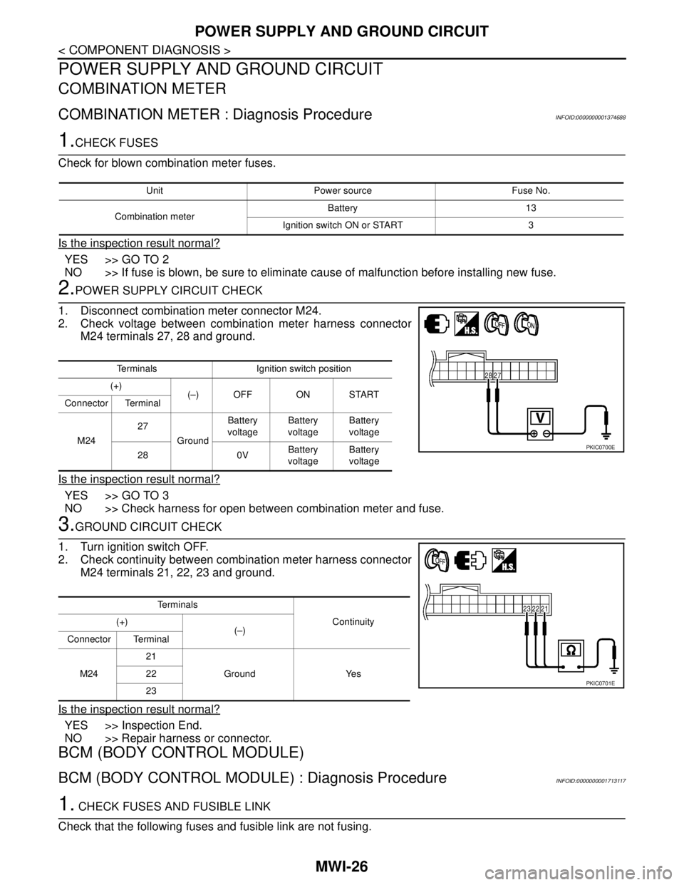
1. Disconnect combination meter connector M24.
2. Check voltage between combination meter harness connector
M24 terminals 27, 28 and ground.
Is the inspection result normal?
YES >> GO TO 3
NO >> Check harness for open between combination meter and fuse.
3.GROUND CIRCUIT CHECK
1. Turn ignition switch OFF.
2. Check continuity between combination meter harness connector
M24 terminals 21, 22, 23 and ground.
Is the inspection result normal?
YES >> Inspection End.
NO >> Repair harness or connector.
BCM (BODY CONTROL MODULE)
BCM (BODY CONTROL MODULE) : Diagnosis ProcedureINFOID:0000000001713117
1. CHECK FUSES AND FUSIBLE LINK
Check that the following fuses and fusible link are not fusing.
Unit Power source Fuse No.
Combination meterBattery 13
Ignition switch ON or START 3
Terminals Ignition switch position
(+)
(–) OFF ON START
Connector Terminal
M2427
GroundBattery
voltageBattery
voltageBattery
voltage
28 0VBattery
voltageBattery
voltage
PKIC0700E
Te r m i n a l s
Continuity (+)
(–)
Connector Terminal
M2421
Ground Yes 22
23
PKIC0701E
Page 4362 of 5883
MWI
BCM (BODY CONTROL MODULE)
MWI-55
< ECU DIAGNOSIS >
C
D
E
F
G
H
I
J
K
L
MB A
O
P
BCM (BODY CONTROL MODULE)
Reference ValueINFOID:0000000001713119
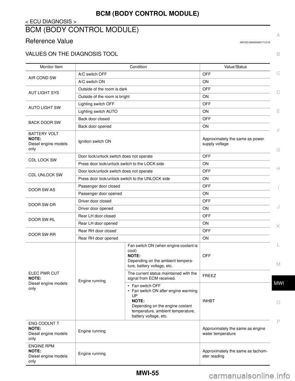
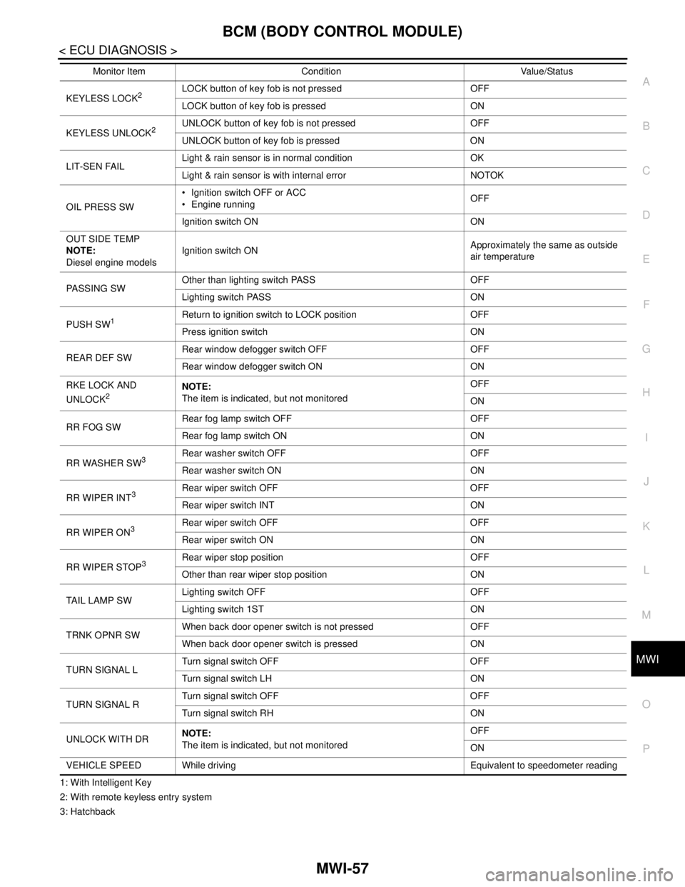
VALUES ON THE DIAGNOSIS TOOL
Monitor Item Condition Value/Status
AIR COND SWA/C switch OFF OFF
A/C switch ON ON
AUT LIGHT SYSOutside of the room is dark OFF
Outside of the room is bright ON
AUTO LIGHT SWLighting switch OFF OFF
Lighting switch AUTO ON
BACK DOOR SWBack door closed OFF
Back door opened ON
BATTERY VOLT
NOTE:
Diesel engine models
onlyIgnition switch ONApproximately the same as power
supply voltage
CDL LOCK SWDoor lock/unlock switch does not operate OFF
Press door lock/unlock switch to the LOCK side ON
CDL UNLOCK SWDoor lock/unlock switch does not operate OFF
Press door lock/unlock switch to the UNLOCK side ON
DOOR SW-ASPassenger door closed OFF
Passenger door opened ON
DOOR SW-DRDriver door closed OFF
Driver door opened ON
DOOR SW-RLRear LH door closed OFF
Rear LH door opened ON
DOOR SW-RRRear RH door closed OFF
Rear RH door opened ON
ELEC PWR CUT
NOTE:
Diesel engine models
onlyEngine runningFan switch ON (when engine coolant is
cool)
NOTE:
Depending on the ambient tempera-
ture, battery voltage, etc.OFF
The current status maintained with the
signal from ECM received.FREEZ
Fan switch OFF
Fan switch ON after engine warming
UP
NOTE:
Depending on the engine coolant
temperature, ambient temperature,
battery voltage, etc.INHBT
ENG COOLNT T
NOTE:
Diesel engine models
onlyEngine runningApproximately the same as engine
water temperature
ENGINE RPM
NOTE:
Diesel engine models
onlyEngine runningApproximately the same as tachom-
eter reading
Page 4363 of 5883

MWI-56
< ECU DIAGNOSIS >
BCM (BODY CONTROL MODULE)
ENGINE RUNEngine stopped OFF
Engine running ON
ENGINE STATUS
NOTE:
Diesel engine models
onlyEngine stopped STOP
While the engine stalls STALL
Engine running RUN
At engine cranking CRA
FA N O N S I GFan switch OFF OFF
Fan switch ON ON
FR FOG SWFront fog lamp switch OFF OFF
Front fog lamp switch ON ON
FR WASHER SWFront washer switch OFF OFF
Front washer switch ON ON
FR WIPER LOWFront wiper switch OFF OFF
Front wiper switch LO ON
FR WIPER HIFront wiper switch OFF OFF
Front wiper switch HI ON
FR WIPER INTFront wiper switch OFF OFF
Front wiper switch INT ON
FR WIPER STOPAny position other than front wiper stop position OFF
Front wiper stop position ON
HAZARD SWWhen hazard switch is not pressed OFF
When hazard switch is pressed ON
LIGHT SW 1STLighting switch OFF OFF
Lighting switch 1st ON
H/L SW POSHeadlamp switch OFF OFF
Headlamp switch 1st ON
HI BEAM SWHigh beam switch OFF OFF
High beam switch HI ON
HOOD SWClose the hood
NOTE:
Vehicles without theft warning system are OFF-fixedOFF
Open the hood ON
H/L WASH SWNOTE:
The item is indicated, but not monitoredOFF
IGN ON SWIgnition switch OFF or ACC OFF
Ignition switch ON ON
IGN SW CANIgnition switch OFF or ACC OFF
Ignition switch ON ON
INT VOLUME Wiper intermittent dial is in a dial position 1 - 7 1 - 7
I-KEY LOCK
1LOCK button of Intelligent Key is not pressed OFF
LOCK button of Intelligent Key is pressed ON
I-KEY UNLOCK
1UNLOCK button of Intelligent Key is not pressed OFF
UNLOCK button of Intelligent Key is pressed ON
KEY SW
2Mechanical key is removed from key cylinder OFF
Mechanical key is inserted to key cylinder ON Monitor Item Condition Value/Status
Page 4364 of 5883
MWI
BCM (BODY CONTROL MODULE)
MWI-57
< ECU DIAGNOSIS >
C
D
E
F
G
H
I
J
K
L
MB A
O
P
1: With Intelligent Key
2: With remote keyless entry system
3: HatchbackKEYLESS LOCK
2LOCK button of key fob is not pressed OFF
LOCK button of key fob is pressed ON
KEYLESS UNLOCK
2UNLOCK button of key fob is not pressed OFF
UNLOCK button of key fob is pressed ON
LIT-SEN FAILLight & rain sensor is in normal condition OK
Light & rain sensor is with internal error NOTOK
OIL PRESS SW Ignition switch OFF or ACC
Engine runningOFF
Ignition switch ON ON
OUT SIDE TEMP
NOTE:
Diesel engine modelsIgnition switch ONApproximately the same as outside
air temperature
PASSING SWOther than lighting switch PASS OFF
Lighting switch PASS ON
PUSH SW
1Return to ignition switch to LOCK position OFF
Press ignition switch ON
REAR DEF SWRear window defogger switch OFF OFF
Rear window defogger switch ON ON
RKE LOCK AND
UNLOCK
2NOTE:
The item is indicated, but not monitoredOFF
ON
RR FOG SWRear fog lamp switch OFF OFF
Rear fog lamp switch ON ON
RR WASHER SW
3Rear washer switch OFF OFF
Rear washer switch ON ON
RR WIPER INT
3Rear wiper switch OFF OFF
Rear wiper switch INT ON
RR WIPER ON
3 Rear wiper switch OFF OFF
Rear wiper switch ON ON
RR WIPER STOP
3Rear wiper stop position OFF
Other than rear wiper stop position ON
TAIL LAMP SWLighting switch OFF OFF
Lighting switch 1ST ON
TRNK OPNR SWWhen back door opener switch is not pressed OFF
When back door opener switch is pressed ON
TURN SIGNAL LTurn signal switch OFF OFF
Turn signal switch LH ON
TURN SIGNAL RTurn signal switch OFF OFF
Turn signal switch RH ON
UNLOCK WITH DRNOTE:
The item is indicated, but not monitoredOFF
ON
VEHICLE SPEED While driving Equivalent to speedometer reading Monitor Item Condition Value/Status
Page 4365 of 5883
MWI-58
< ECU DIAGNOSIS >
BCM (BODY CONTROL MODULE)
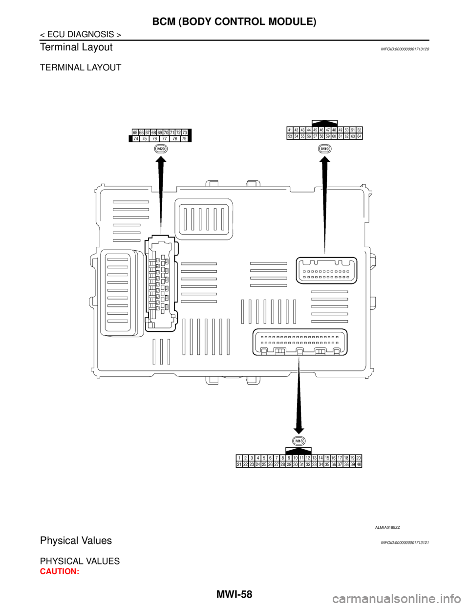
Terminal Layout
INFOID:0000000001713120
TERMINAL LAYOUT
Physical ValuesINFOID:0000000001713121
PHYSICAL VALUES
CAUTION:
ALMIA0185ZZ