2007 NISSAN TIIDA Body
[x] Cancel search: BodyPage 4535 of 5883
RF-1
BODY EXTERIOR, DOORS, ROOF & VEHICLE SECURITY
C
D
E
F
G
H
I
J
L
M
SECTION RF
A
B
RF
N
O
P
CONTENTS
ROOF
PRECAUTION ...............................................3
PRECAUTIONS ...................................................3
Precaution for Supplemental Restraint System
(SRS) "AIR BAG" and "SEAT BELT PRE-TEN-
SIONER" ...................................................................
3
PREPARATION ............................................4
PREPARATION ...................................................4
Commercial Service Tool ..........................................4
BASIC INSPECTION ....................................5
DIAGNOSIS AND REPAIR WORKFLOW ..........5
Work Flow .................................................................5
INSPECTION AND ADJUSTMENT .....................7
ADDITIONAL SERVICE WHEN REPLACING
CONTROL UNIT ..........................................................
7
ADDITIONAL SERVICE WHEN REPLACING
CONTROL UNIT : Description ..................................
7
ADDITIONAL SERVICE WHEN REPLACING
CONTROL UNIT : Special Repair Requirement .......
7
FUNCTION DIAGNOSIS ...............................8
SUNROOF SYSTEM ...........................................8
System Diagram .......................................................8
System Description ...................................................8
Component Parts Location ......................................9
Component Description ............................................9
DIAGNOSIS SYSTEM (BCM) ............................10
COMMON ITEM .........................................................10
COMMON ITEM : CONSULT-III Function (BCM -
COMMON ITEM) .....................................................
10
RETAINED PWR .......................................................10
RETAINED PWR : CONSULT-III Function (BCM -
RETAINED PWR) ...................................................
10
COMPONENT DIAGNOSIS .........................11
POWER SUPPLY AND GROUND CIRCUIT ....11
SUNROOF MOTOR ASSEMBLY ..............................11
SUNROOF MOTOR ASSEMBLY :
Diagnosis Procedure ..............................................
11
SUNROOF MOTOR ASSEMBLY : Special Repair
Requirement ............................................................
12
SUNROOF SWITCH CIRCUIT ..........................13
Description ...............................................................13
Component Function Check ..................................13
Diagnosis Procedure ...............................................13
DOOR SWITCH .................................................15
Description ...............................................................15
Component Function Check ....................................15
Diagnosis Procedure ...............................................15
ECU DIAGNOSIS .........................................17
BCM (BODY CONTROL MODULE) .................17
Reference Value ......................................................17
SUNROOF SYSTEM .........................................18
Reference Value ......................................................18
Wiring Diagram ........................................................19
SYMPTOM DIAGNOSIS ..............................24
SQUEAK AND RATTLE TROUBLE DIAG-
NOSES ..............................................................
24
Work Flow ................................................................24
Generic Squeak and Rattle Troubleshooting ...........26
Diagnostic Worksheet ..............................................28
ON-VEHICLE REPAIR .................................30
SUNROOF SYSTEM .........................................30
Inspection ................................................................30
Fitting Adjustment ....................................................32
Exploded View .........................................................34
Page 4551 of 5883
BCM (BODY CONTROL MODULE)
RF-17
< ECU DIAGNOSIS >
C
D
E
F
G
H
I
J
L
MA
B
RF
N
O
P
ECU DIAGNOSIS
BCM (BODY CONTROL MODULE)
Reference ValueINFOID:0000000001724572
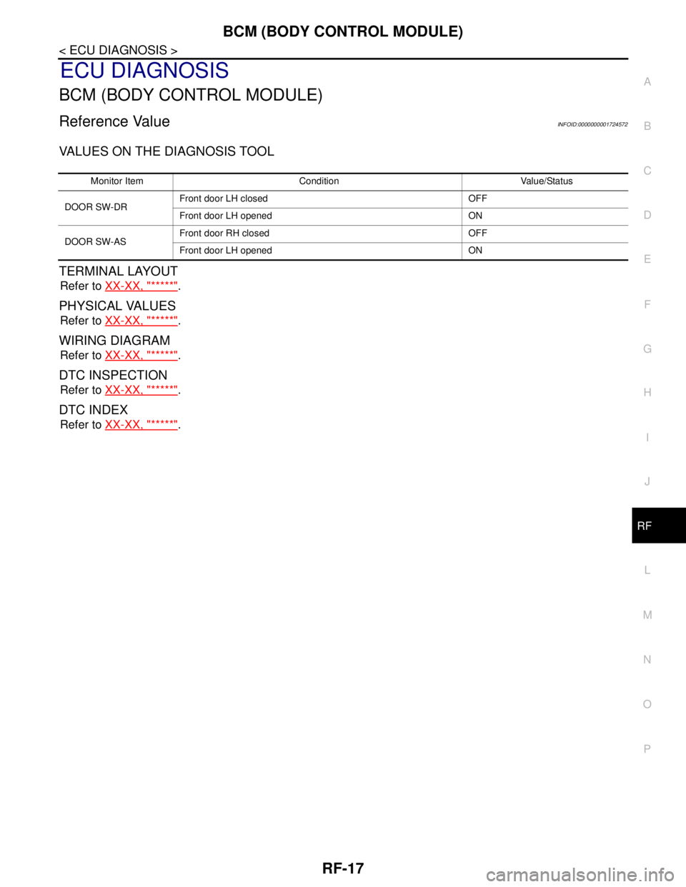
VALUES ON THE DIAGNOSIS TOOL
TERMINAL LAYOUT
Refer to XX-XX, "*****".
PHYSICAL VALUES
Refer to XX-XX, "*****".
WIRING DIAGRAM
Refer to XX-XX, "*****".
DTC INSPECTION
Refer to XX-XX, "*****".
DTC INDEX
Refer to XX-XX, "*****".
Monitor Item Condition Value/Status
DOOR SW-DRFront door LH closed OFF
Front door LH opened ON
DOOR SW-ASFront door RH closed OFF
Front door LH opened ON
Page 4559 of 5883
SQUEAK AND RATTLE TROUBLE DIAGNOSES
RF-25
< SYMPTOM DIAGNOSIS >
C
D
E
F
G
H
I
J
L
MA
B
RF
N
O
P
If possible, drive the vehicle with the customer until the noise is duplicated. Note any additional information on
the Diagnostic Worksheet regarding the conditions or location of the noise. This information can be used to
duplicate the same conditions when you confirm the repair.
If the noise can be duplicated easily during the test drive, to help identify the source of the noise, try to dupli-
cate the noise with the vehicle stopped by doing one or all of the following:
1) Close a door.
2) Tap or push/pull around the area where the noise appears to be coming from.
3) Rev the engine.
4) Use a floor jack to recreate vehicle “twist”.
5) At idle, apply engine load (electrical load, half-clutch on M/T model, drive position on A/T model).
6) Raise the vehicle on a hoist and hit a tire with a rubber hammer.
Drive the vehicle and attempt to duplicate the conditions the customer states exist when the noise occurs.
If it is difficult to duplicate the noise, drive the vehicle slowly on an undulating or rough road to stress the
vehicle body.
CHECK RELATED SERVICE BULLETINS
After verifying the customer concern or symptom, check ASIST for Technical Service Bulletins (TSBs) related
to that concern or symptom.
If a TSB relates to the symptom, follow the procedure to repair the noise.
LOCATE THE NOISE AND IDENTIFY THE ROOT CAUSE
1. Narrow down the noise to a general area. To help pinpoint the source of the noise, use a listening tool
(Engine Ear or mechanics stethoscope).
2. Narrow down the noise to a more specific area and identify the cause of the noise by:
removing the components in the area that you suspect the noise is coming from.
Do not use too much force when removing clips and fasteners, otherwise clips and fastener can be broken
or lost during the repair, resulting in the creation of new noise.
tapping or pushing/pulling the component that you suspect is causing the noise.
Do not tap or push/pull the component with excessive force, otherwise the noise will be eliminated only tem-
porarily.
feeling for a vibration with your hand by touching the component(s) that you suspect is (are) causing the
noise.
placing a piece of paper between components that you suspect are causing the noise.
looking for loose components and contact marks.
Refer to RF-26, "
Generic Squeak and Rattle Troubleshooting".
REPAIR THE CAUSE
If the cause is a loose component, tighten the component securely.
If the cause is insufficient clearance between components:
- separate components by repositioning or loosening and retightening the component, if possible.
- insulate components with a suitable insulator such as urethane pads, foam blocks, felt cloth tape or urethane
tape are available through your authorized Nissan Parts Department.
CAUTION:
Do not use excessive force as many components are constructed of plastic and may be damaged.
NOTE:
Always check with the Parts Department for the latest parts information.
Each item can be ordered separately as needed.
URETHANE PADS [1.5 mm (0.059 in) thick]
Insulates connectors, harness, etc.
76268-9E005: 100 × 135 mm (3.94 × 5.31 in)/76884-71L01: 60 × 85 mm (2.36 × 3.35 in)/76884-71L02: 15 ×
25 mm (0.59 × 0.98 in)
INSULATOR (Foam blocks)
Insulates components from contact. Can be used to fill space behind a panel.
73982-9E000: 45 mm (1.77 in) thick, 50 × 50 mm (1.97 × 1.97 in)/73982-50Y00: 10 mm (0.39 in) thick, 50
× 50 mm (1.97 × 1.97 in)
INSULATOR (Light foam block)
80845-71L00: 30 mm (1.18 in) thick, 30 × 50 mm (1.18 × 1.97 in)
FELT CLOTH TAPE
Used to insulate where movement does not occur. Ideal for instrument panel applications.
68370-4B000: 15 × 25 mm (0.59 × 0.98 in) pad/68239-13E00: 5 mm (0.20 in) wide tape roll
Page 4566 of 5883
RF-32
< ON-VEHICLE REPAIR >
SUNROOF SYSTEM
1. Remove headlining. Refer to INT-29, "Component".
2. Visually check drain hoses for:
Proper connection at sunroof unit assembly.
Damage, pinch, cracks, deterioration.
Proper fastening and routing on body panels.
3. Pour water through drain hoses to determine watertight performance.
If a damaged or leaking portion in any drain hose is found, replace entire drain hose as an assembly.
Fitting AdjustmentINFOID:0000000001724430
GAP ADJUSTMENT
1. Tilt up glass lid.
2. Loosen glass lid bolts, then tilt down glass lid.
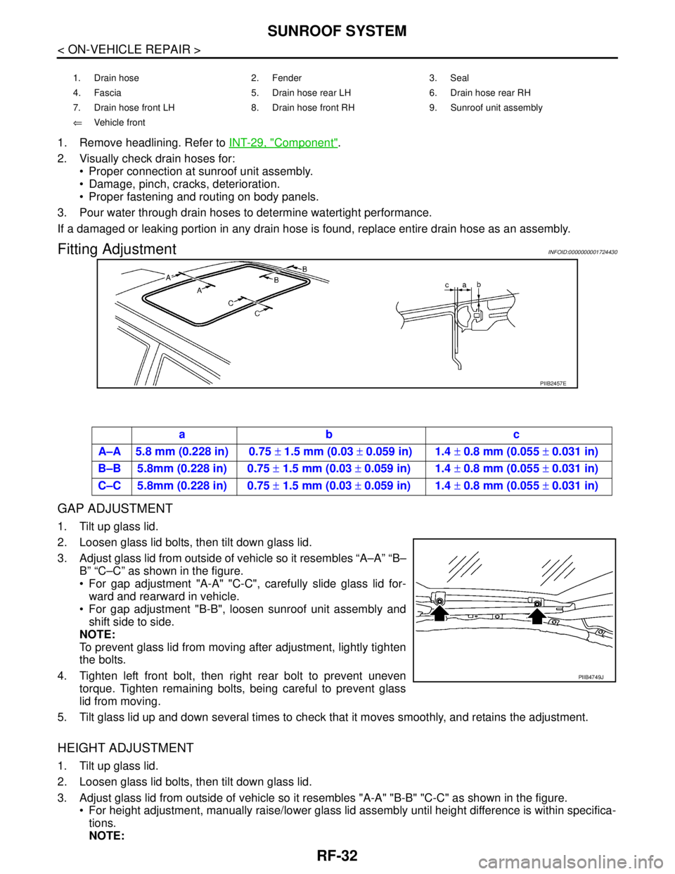
3. Adjust glass lid from outside of vehicle so it resembles “A–A” “B–
B” “C–C” as shown in the figure.
For gap adjustment "A-A" "C-C", carefully slide glass lid for-
ward and rearward in vehicle.
For gap adjustment "B-B", loosen sunroof unit assembly and
shift side to side.
NOTE:
To prevent glass lid from moving after adjustment, lightly tighten
the bolts.
4. Tighten left front bolt, then right rear bolt to prevent uneven
torque. Tighten remaining bolts, being careful to prevent glass
lid from moving.
5. Tilt glass lid up and down several times to check that it moves smoothly, and retains the adjustment.
HEIGHT ADJUSTMENT
1. Tilt up glass lid.
2. Loosen glass lid bolts, then tilt down glass lid.
3. Adjust glass lid from outside of vehicle so it resembles "A-A" "B-B" "C-C" as shown in the figure.
For height adjustment, manually raise/lower glass lid assembly until height difference is within specifica-
tions.
NOTE:
1. Drain hose 2. Fender 3. Seal
4. Fascia 5. Drain hose rear LH 6. Drain hose rear RH
7. Drain hose front LH 8. Drain hose front RH 9. Sunroof unit assembly
⇐Vehicle front
PIIB2457E
ab c
A–A 5.8 mm (0.228 in) 0.75 ± 1.5 mm (0.03 ± 0.059 in) 1.4 ± 0.8 mm (0.055 ± 0.031 in)
B–B 5.8mm (0.228 in) 0.75 ± 1.5 mm (0.03 ± 0.059 in) 1.4 ± 0.8 mm (0.055 ± 0.031 in)
C–C 5.8mm (0.228 in) 0.75 ± 1.5 mm (0.03 ± 0.059 in) 1.4 ± 0.8 mm (0.055 ± 0.031 in)
PIIB4749J
Page 4581 of 5883
SHOCK ABSORBER
RSU-9
< ON-VEHICLE REPAIR >
C
D
F
G
H
I
J
K
L
MA
B
RSU
N
O
P
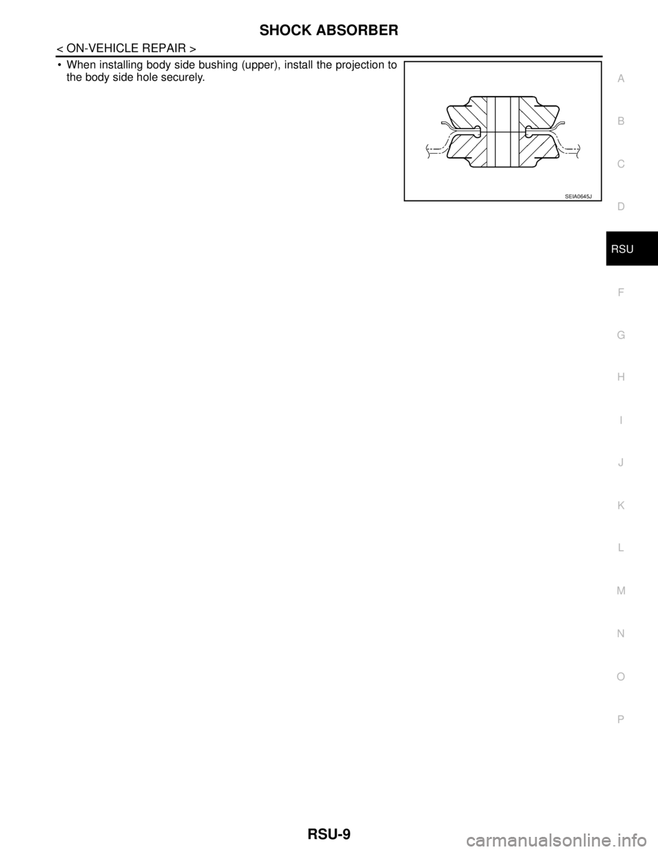
When installing body side bushing (upper), install the projection to
the body side hole securely.
SEIA0645J
Page 4583 of 5883
REAR SUSPENSION BEAM
RSU-11
< ON-VEHICLE REPAIR >
C
D
F
G
H
I
J
K
L
MA
B
RSU
N
O
P
REAR SUSPENSION BEAM
Removal and InstallationINFOID:0000000001724580
REMOVAL
1. Remove rear tires from vehicle using power tool.
2. Separate parking brake rear cable from rear drum brake and rear suspension beam. Refer to PB-4, "
On-
Vehicle Service" .
3. Remove wheel sensor and wheel sensor harness from wheel hub and bearing assembly and rear suspen-
sion beam. Refer to BRC-83, "
Removal and Installation" .
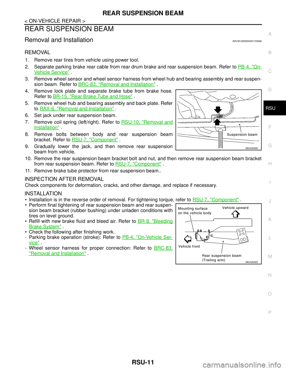
4. Remove lock plate and separate brake tube from brake hose.
Refer to BR-15, "
Rear Brake Tube and Hose" .
5. Remove wheel hub and bearing assembly and back plate. Refer
to RAX-6, "
Removal and Installation" .
6. Set jack under rear suspension beam.
7. Remove coil spring (left/right). Refer to RSU-10, "
Removal and
Installation" .
8. Remove bolts between body and rear suspension beam
bracket. Refer to RSU-7, "
Component" .
9. Gradually lower the jack, and then remove rear suspension
beam from vehicle.
10. Remove the rear suspension beam bracket bolt and nut, and then remove rear suspension beam bracket
from rear suspension beam. Refer to RSU-7, "
Component" .
11. Remove brake tube protector from rear suspension beam..
INSPECTION AFTER REMOVAL
Check components for deformation, cracks, and other damage, and replace if necessary.
INSTALLATION
Installation is in the reverse order of removal. For tightening torque, refer to RSU-7, "Component" .
Perform final tightening of rear suspension beam and rear suspen-
sion beam bracket (rubber bushing) under unladen conditions with
tires on level ground.
Refill with new brake fluid and bleed air. Refer to BR-8, "
Bleeding
Brake System" .
Check the following after finishing work.
- Parking brake operation (stroke): Refer to PB-4, "
On-Vehicle Ser-
vice" .
- Wheel sensor harness for proper connection: Refer to BRC-83,
"Removal and Installation" .
MEIA0029E
MEIA0030E
Page 4596 of 5883
SB-12
< ON-VEHICLE REPAIR >
TOP TETHER STRAP CHILD RESTRAINT
TOP TETHER STRAP CHILD RESTRAINT
Removal and InstallationINFOID:0000000001366763
REMOVAL
1. Disconnect the negative battery cable.
2. Remove the rear parcel shelf finisher. Refer to INT-26, "
Removal and Installation".
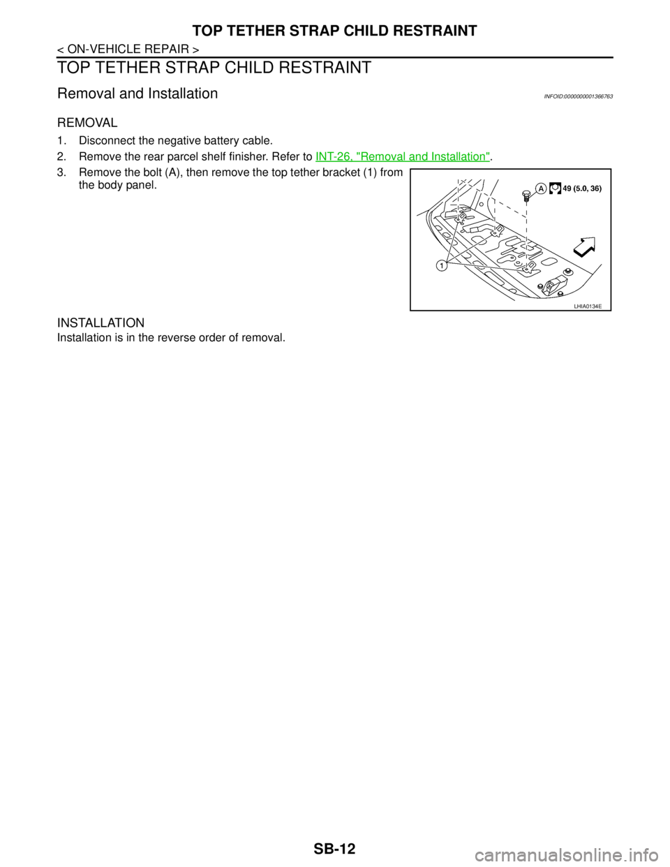
3. Remove the bolt (A), then remove the top tether bracket (1) from
the body panel.
INSTALLATION
Installation is in the reverse order of removal.
LHIA0134E
Page 4597 of 5883
SE-1
BODY INTERIOR
C
D
E
F
G
H
I
K
L
M
SECTION SE
A
B
SE
N
O
P
CONTENTS
SEAT
COMPONENT DIAGNOSIS ..........................2
HEATED SEAT ....................................................2
Wiring Diagram .........................................................2
SYMPTOM DIAGNOSIS ...............................5
SQUEAK AND RATTLE TROUBLE DIAG-
NOSES ................................................................
5
Work Flow .................................................................5
Generic Squeak and Rattle Troubleshooting ............7
Diagnostic Worksheet ...............................................9
PRECAUTION ..............................................11
PRECAUTIONS ..................................................11
Precaution for Supplemental Restraint System
(SRS) "AIR BAG" and "SEAT BELT PRE-TEN-
SIONER" .................................................................
11
PREPARATION ...........................................12
PREPARATION ..................................................12
Special Service Tool ...............................................12
Commercial Service Tool ........................................12
REMOVAL AND INSTALLATION ...............13
FRONT SEAT ....................................................13
Exploded View .........................................................13
Removal and Installation .........................................14
REAR SEAT ......................................................16
Exploded View .........................................................16
Removal and Installation .........................................18
Removal and Installation .........................................20
ON-VEHICLE REPAIR .................................21
FRONT SEAT ....................................................21
Exploded View .........................................................21
Disassembly and Assembly .....................................22
REAR SEAT ......................................................24
Exploded View .........................................................24
Disassembly and Assembly .....................................26
Disassembly and Assembly .....................................27