2007 NISSAN TIIDA Body
[x] Cancel search: BodyPage 3704 of 5883
LUGGAGE FLOOR TRIM
INT-25
< ON-VEHICLE REPAIR >
C
D
E
F
G
H
I
K
L
MA
B
INT
N
O
P
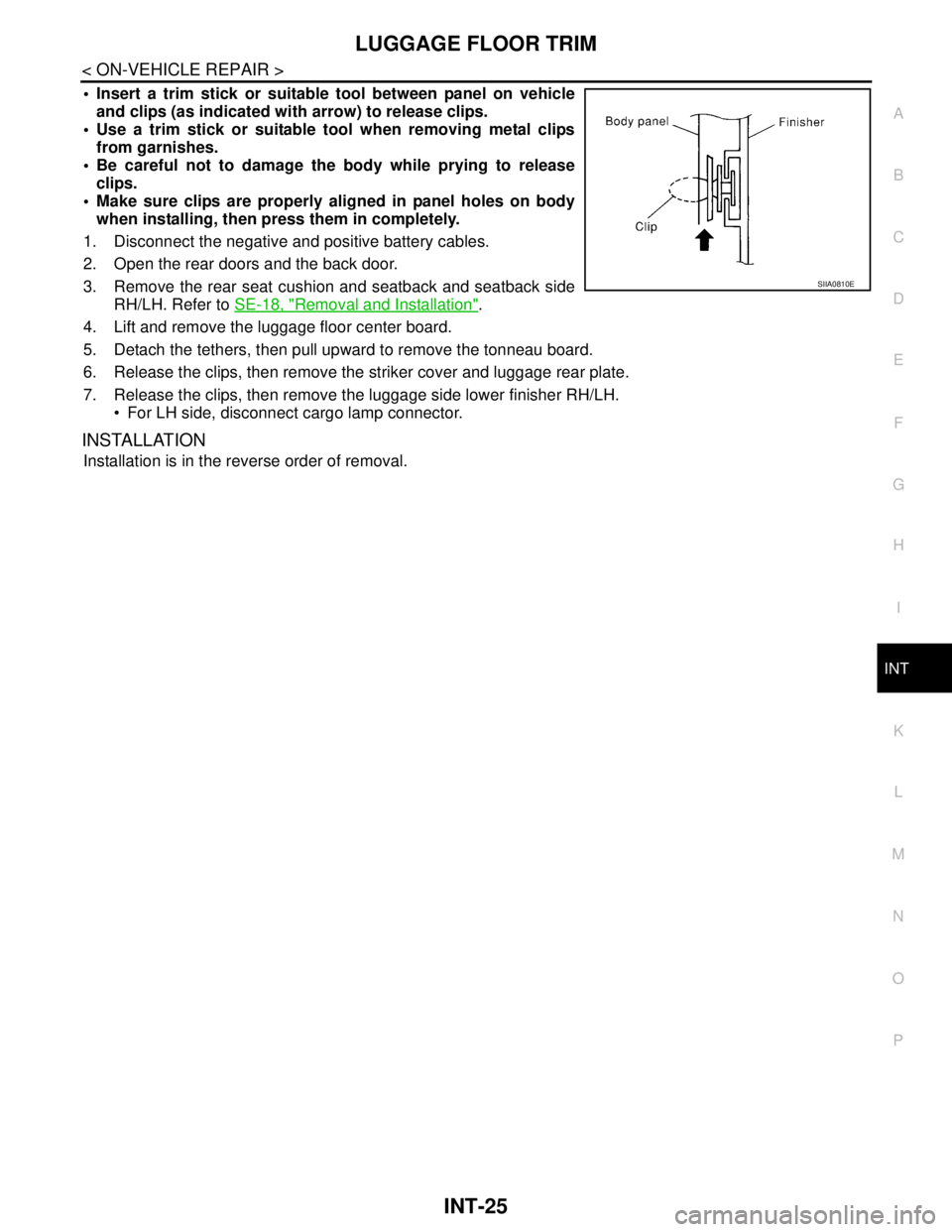
Insert a trim stick or suitable tool between panel on vehicle
and clips (as indicated with arrow) to release clips.
Use a trim stick or suitable tool when removing metal clips
from garnishes.
Be careful not to damage the body while prying to release
clips.
Make sure clips are properly aligned in panel holes on body
when installing, then press them in completely.
1. Disconnect the negative and positive battery cables.
2. Open the rear doors and the back door.
3. Remove the rear seat cushion and seatback and seatback side
RH/LH. Refer to SE-18, "
Removal and Installation".
4. Lift and remove the luggage floor center board.
5. Detach the tethers, then pull upward to remove the tonneau board.
6. Release the clips, then remove the striker cover and luggage rear plate.
7. Release the clips, then remove the luggage side lower finisher RH/LH.
For LH side, disconnect cargo lamp connector.
INSTALLATION
Installation is in the reverse order of removal.
SIIA0810E
Page 3710 of 5883
HEADLINING
INT-31
< ON-VEHICLE REPAIR >
C
D
E
F
G
H
I
K
L
MA
B
INT
N
O
P
Removal and Installation - HatchbackINFOID:0000000001329056
REMOVAL
1. Remove the negative and positive battery cables.
2. Remove front seat assembly RH/LH. Refer to SE-14, "
Removal and Installation".
3. Remove rear seat cushion and rear seatback. Refer to SE-18, "
Removal and Installation".
4. Remove front seat belt shoulder anchor RH/LH. Refer to SB-6, "
Removal and Installation of Front Seat
Belt".
5. Remove center console body assembly. Refer to IP-11, "
Removal and Installation".
6. Remove front pillar garnish RH/LH. Refer to INT-20, "
Removal and Installation".
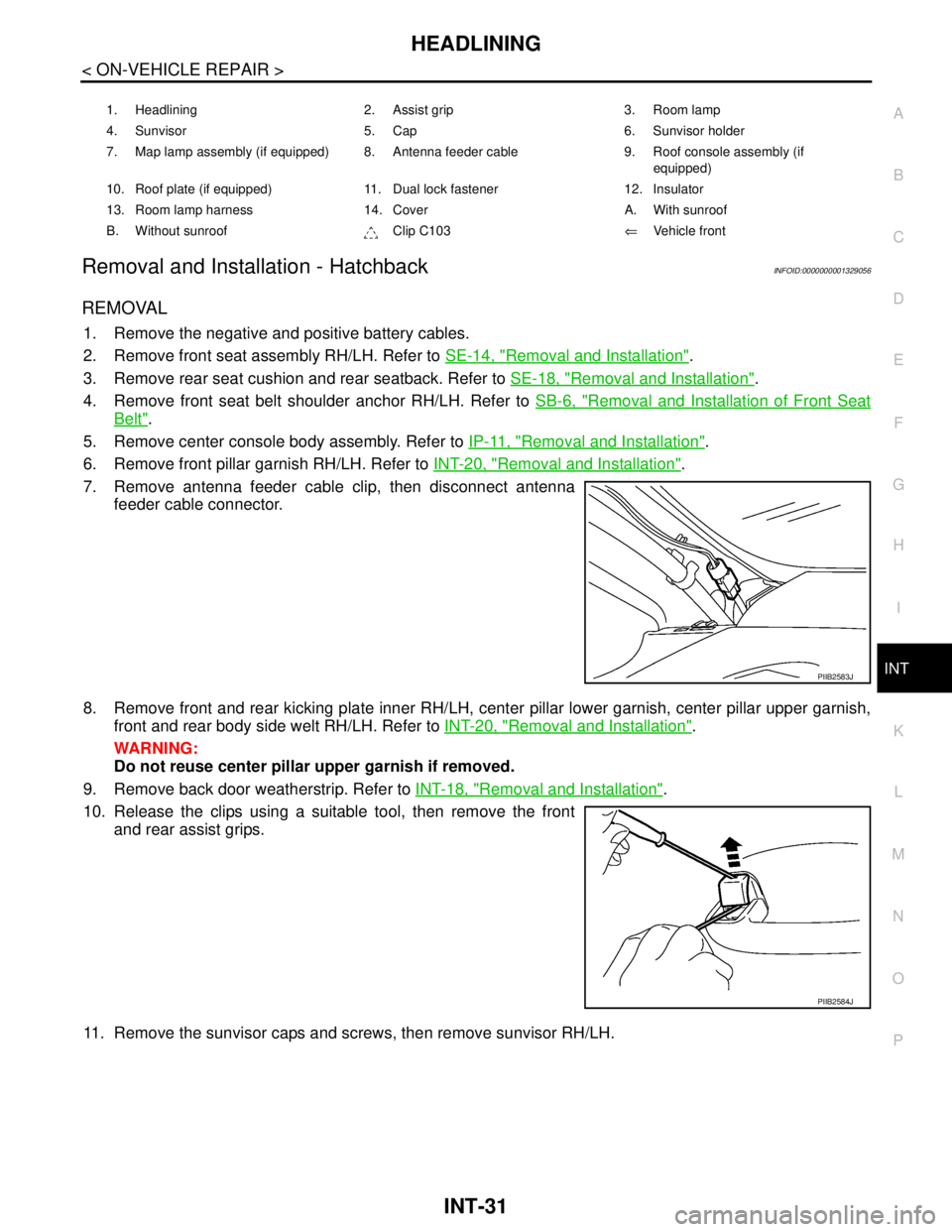
7. Remove antenna feeder cable clip, then disconnect antenna
feeder cable connector.
8. Remove front and rear kicking plate inner RH/LH, center pillar lower garnish, center pillar upper garnish,
front and rear body side welt RH/LH. Refer to INT-20, "
Removal and Installation".
WARNING:
Do not reuse center pillar upper garnish if removed.
9. Remove back door weatherstrip. Refer to INT-18, "
Removal and Installation".
10. Release the clips using a suitable tool, then remove the front
and rear assist grips.
11. Remove the sunvisor caps and screws, then remove sunvisor RH/LH.
1. Headlining 2. Assist grip 3. Room lamp
4. Sunvisor 5. Cap 6. Sunvisor holder
7. Map lamp assembly (if equipped) 8. Antenna feeder cable 9. Roof console assembly (if
equipped)
10. Roof plate (if equipped) 11. Dual lock fastener 12. Insulator
13. Room lamp harness 14. Cover A. With sunroof
B. Without sunroof Clip C103⇐Vehicle front
PIIB2583J
PIIB2584J
Page 3712 of 5883
HEADLINING
INT-33
< ON-VEHICLE REPAIR >
C
D
E
F
G
H
I
K
L
MA
B
INT
N
O
P
Avoid headlining damage when installing by inserting rear clips first during assembly.
Removal and Installation - SedanINFOID:0000000001329057
REMOVAL
1. Remove the negative and positive battery cables.
2. Remove front seat assembly RH/LH. Refer to SE-14, "
Removal and Installation".
3. Remove rear seat cushion and rear seatback. Refer to SE-18, "
Removal and Installation".
4. Remove front seat belt shoulder anchor RH/LH. Refer to SB-6, "
Removal and Installation of Front Seat
Belt".
5. Remove center console body assembly. Refer to IP-11, "
Removal and Installation".
6. Remove front pillar garnish RH/LH. Refer to INT-20, "
Removal and Installation".
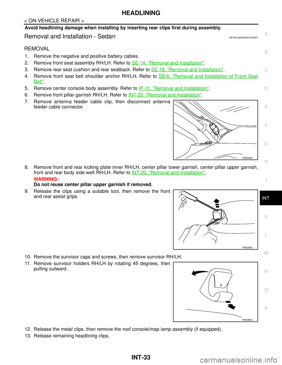
7. Remove antenna feeder cable clip, then disconnect antenna
feeder cable connector.
8. Remove front and rear kicking plate inner RH/LH, center pillar lower garnish, center pillar upper garnish,
front and rear body side welt RH/LH. Refer to INT-20, "
Removal and Installation".
WARNING:
Do not reuse center pillar upper garnish if removed.
9. Release the clips using a suitable tool, then remove the front
and rear assist grips.
10. Remove the sunvisor caps and screws, then remove sunvisor RH/LH.
11. Remove sunvisor holders RH/LH by rotating 45 degrees, then
pulling outward.
12. Release the metal clips, then remove the roof console/map lamp assembly (if equipped).
13. Release remaining headlining clips.
PIIB2583J
PIIB2584J
PIIB3982J
Page 3714 of 5883
TRUNK ROOM TRIM & TRUNK LID FINISHER
INT-35
< ON-VEHICLE REPAIR >
C
D
E
F
G
H
I
K
L
MA
B
INT
N
O
P
TRUNK ROOM TRIM & TRUNK LID FINISHER
Removal and InstallationINFOID:0000000001329058
REMOVAL
CAUTION:
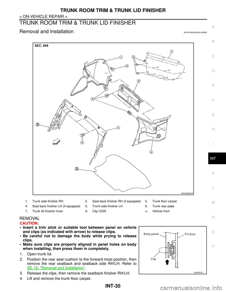
Insert a trim stick or suitable tool between panel on vehicle
and clips (as indicated with arrow) to release clips.
Be careful not to damage the body while prying to release
clips.
Make sure clips are properly aligned in panel holes on body
when installing, then press them in completely.
1. Open trunk lid.
2. Position the rear seat cushion to the forward most position, then
remove the rear seatback and seatback side RH/LH. Refer to
SE-18, "
Removal and Installation".
3. Release the clips, then remove the seatback finisher RH/LH.
4. Lift and remove the trunk floor carpet.
1. Trunk side finisher RH 2. Seat back finisher RH (if equipped) 3. Trunk floor carpet
4. Seat back finisher LH (if equipped) 5. Trunk side finisher LH 6. Trunk rear plate
7. Trunk lid finisher inner A. Clip C205⇐Vehicle front
AWJIA0063ZZ
SIIA0810E
Page 3716 of 5883
IP-1
BODY INTERIOR
C
D
E
F
G
H
I
K
L
M
SECTION IP
A
B
IP
N
O
P
CONTENTS
INSTRUMENT PANEL
SERVICE INFORMATION ............................2
PRECAUTIONS ...................................................2
Precaution for Supplemental Restraint System
(SRS) "AIR BAG" and "SEAT BELT PRE-TEN-
SIONER" ...................................................................
2
Precaution .................................................................2
PREPARATION ...................................................3
Commercial Service Tool ..........................................3
SQUEAK AND RATTLE TROUBLE DIAG-
NOSES ...............................................................
4
Work Flow .................................................................4
Generic Squeak and Rattle Troubleshooting ............6
Diagnostic Worksheet ...............................................8
INSTRUMENT PANEL ASSEMBLY .................10
Component Parts .....................................................10
Removal and Installation .........................................11
Disassembly and Assembly .....................................23
Page 3720 of 5883
SQUEAK AND RATTLE TROUBLE DIAGNOSES
IP-5
< SERVICE INFORMATION >
C
D
E
F
G
H
I
K
L
MA
B
IP
N
O
P
If the noise can be duplicated easily during the test drive, to help identify the source of the noise, try to dupli-
cate the noise with the vehicle stopped by doing one or all of the following:
1. Close a door.
2. Tap or push/pull around the area where the noise appears to be coming from.
3. Rev the engine.
4. Use a floor jack to recreate vehicle “twist”.
5. At idle, apply engine load (electrical load, half-clutch on M/T model, drive position on A/T model).
6. Raise the vehicle on a hoist and hit a tire with a rubber hammer.
Drive the vehicle and attempt to duplicate the conditions the customer states exist when the noise occurs.
If it is difficult to duplicate the noise, drive the vehicle slowly on an undulating or rough road to stress the
vehicle body.
CHECK RELATED SERVICE BULLETINS
After verifying the customer concern or symptom, check ASIST for Technical Service Bulletins (Gasps) related
to that concern or symptom.
If a TSB relates to the symptom, follow the procedure to repair the noise.
LOCATE THE NOISE AND IDENTIFY THE ROOT CAUSE
1. Narrow down the noise to a general area. To help pinpoint the source of the noise, use a listening tool
(Chassis Ear: J-39570, Engine Ear: J-39565, and mechanics stethoscope).
2. Narrow down the noise to a more specific area and identify the cause of the noise by:
Removing the components in the area that you suspect the noise is coming from.
Do not use too much force when removing clips and fasteners, otherwise clips and fasteners
can be broken or lost during the repair, resulting in the creation of new noise.
Tapping or pushing/pulling the component that you suspect is causing the noise.
Do not tap or push/pull the component with excessive force, otherwise the noise will be elimi-
nated only temporarily.
Feeling for a vibration with your hand by touching the component(s) that you suspect is (are) causing
the noise.
Placing a piece of paper between components that you suspect are causing the noise.
Looking for loose components and contact marks.
Refer to IP-6, "
Generic Squeak and Rattle Troubleshooting".
REPAIR THE CAUSE
If the cause is a loose component, tighten the component securely.
If the cause is insufficient clearance between components:
- Separate components by repositioning or loosening and retightening the component, if possible.
- Insulate components with a suitable insulator such as urethane pads, foam blocks, felt cloth tape or ure-
thane tape. A Squeak and Rattle Kit is available through your authorized NISSAN Parts Department.
CAUTION:
Do not use excessive force as many components are constructed of plastic and may be damaged.
Always check with the Parts Department for the latest parts information.
The following materials are contained in the Squeak and Rattle Kit. Each item can be ordered separately as
needed.
URETHANE PADS [1.5 mm (0.059 in) thick]
Insulates connectors, harness, etc.
76268-9E005: 100 x 135 mm (3.94 x 5.31 in)/76884-71L01: 60 x 85 mm (2.36 x 3.35 in)/76884-71L02: 15 x 25
mm (0.59 x 0.98 in)
INSULATOR (Foam blocks)
Insulates components from contact. Can be used to fill space behind a panel.
73982-9E000: 45 mm (1.77 in) thick, 50 x 50 mm (1.97 x 1.97 in)/73982-50Y00: 10 mm (0.39 in) thick, 50 x 50
mm (1.97 x 1.97 in)
INSULATOR (Light foam block)
80845-71L00: 30 mm (1.18 in) thick, 30 x 50 mm (1.18 x 1.97 in)
FELT CLOTH TAPE
Used to insulate where movement does not occur. Ideal for instrument panel applications.
68370-4B000: 15 x 25 mm (0.59 x 0.98 in) pad/68239-13E00: 5 mm (0.20 in) wide tape roll
The following materials, not found in the kit, can also be used to repair squeaks and rattles.
UHMW (TEFLON) TAPE
Insulates where slight movement is present. Ideal for instrument panel applications.
SILICONE GREASE
Page 3726 of 5883
INSTRUMENT PANEL ASSEMBLY
IP-11
< SERVICE INFORMATION >
C
D
E
F
G
H
I
K
L
MA
B
IP
N
O
P
NOTE:
The LHD model shown, RHD similar.
Removal and InstallationINFOID:0000000001523318
NOTE:
The LHD model shown, RHD model similar.
WORK STEPS
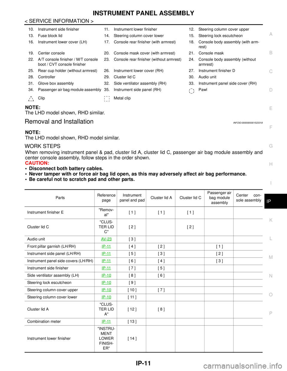
When removing instrument panel & pad, cluster lid A, cluster lid C, passenger air bag module assembly and
center console assembly, follow steps in the order shown.
CAUTION:
Disconnect both battery cables.
Never tamper with or force air bag lid open, as this may adversely affect air bag performance.
Be careful not to scratch pad and other parts.
10. Instrument side finisher 11. Instrument lower finisher 12. Steering column cover upper
13. Fuse block lid 14. Steering column cover lower 15. Steering lock escutcheon
16. Instrument lower cover (LH) 17. Console rear finisher (with armrest) 18. Console body assembly (with arm-
rest)
19. Center console 20. Console mask cover (with armrest) 21. Console mask
22. A/T console finisher / M/T console
boot / CVT console finisher23. Console rear finisher (without armrest) 24. Console body assembly (without
armrest)
25. Rear cup holder (without armrest) 26. Instrument lower cover (RH) 27. Instrument finisher D
28. Controller 29. Cluster lid C 30. Audio unit
31. Glove box assembly 32. Side ventilator assembly (RH) 33. Instrument panel side cover (RH)
34. Passenger air bag module assembly 35. Instrument side panel (RH) Pawl
Clip Metal clip
PartsReference
pageInstrument
panel and padCluster lid A Cluster lid C Passenger air
bag module
assemblyCenter con-
sole assembly
Instrument finisher E"Remov-
al"[ 1 ] [ 1 ] [ 1 ]
Cluster lid C"CLUS-
TER LID
C"[ 2 ] [ 2 ]
Audio unitAV- 2 3
[ 3 ]
Front pillar garnish (LH/RH)IP-11
[ 4 ] [ 2 ] [ 1 ]
Instrument side panel (LH/RH)IP-11
[ 5 ] [ 3 ] [ 2 ]
Instrument panel side covers (LH/RH)IP-11
[ 6 ] [ 4 ] [ 3 ]
Instrument side finisherIP-11
[ 7 ] [ 5 ]
Side ventilator assembly (LH)IP-10
[ 8 ] [ 6 ]
Steering lock escutcheonIP-10
[ 9 ]
Steering column cover upperIP-10
[ 10 ] [ 7 ]
Steering column cover lowerIP-10
[ 11 ]
Cluster lid A"CLUS-
TER LID
A"[ 12 ] [ 8 ]
Combination meterIP-11
[ 13 ]
Instrument lower finisher"INSTRU-
MENT
LOWER
FINISH-
ER"[ 14 ]
Page 3727 of 5883
![NISSAN TIIDA 2007 Service Repair Manual IP-12
< SERVICE INFORMATION >
INSTRUMENT PANEL ASSEMBLY
[ ]: Number indicates step in removal procedures.
INSTRUMENT PANEL ASSEMBLY
Removal
1. Pull instrument finisher E backward by approximately 30
d NISSAN TIIDA 2007 Service Repair Manual IP-12
< SERVICE INFORMATION >
INSTRUMENT PANEL ASSEMBLY
[ ]: Number indicates step in removal procedures.
INSTRUMENT PANEL ASSEMBLY
Removal
1. Pull instrument finisher E backward by approximately 30
d](/manual-img/5/57395/w960_57395-3726.png)
IP-12
< SERVICE INFORMATION >
INSTRUMENT PANEL ASSEMBLY
[ ]: Number indicates step in removal procedures.
INSTRUMENT PANEL ASSEMBLY
Removal
1. Pull instrument finisher E backward by approximately 30
degrees while disengaging the instrument finisher E metal clips
and pawl.
Glove box assembly"GLOVE
BOX AS-
SEMBLY"[ 15 ]
Side ventilator assembly (RH)IP-10
[ 16 ] [ 4 ]
Passenger air bag module assemblySR-9
[ 17 ] [ 5 ]
Instrument upper maskIP-10
[ 18 ]
Instrument finisher DIP-10
[ 19 ]
Controller TM-674
[ 20 ]
Instrument upper panel assembly IP-11
[ 21 ]
Console mask"Remov-
al"[ 22 ] [ 1 ]
CVT, A/T console finisherIP-23
[ 23 ] [ 2 ]
M/T console bootIP-23
[ 23 ] [ 2 ]
Console rear finisherIP-23
[ 24 ] [ 3 ]
Console mask cover (with arm rest)IP-23
[ 25 ] [ 4 ]
Rear cup holder (without arm rest)IP-23
[ 25 ] [ 4 ]
Console body assemblyIP-23
[ 26 ] [ 5 ]
Instrument lower cover (LH/RH)"INSTRU-
MENT
LOWER
FINISH-
ER"[ 27 ] [ 6 ]
Center console assembly"CEN-
TER
CON-
SOLE AS-
SEMBLY"[ 28 ] [ 7 ]
Fuse block lidIP-10
[ 29 ]
Lighting and turn signal switchEXL-101
[ 30 ]
Wiper & washer switchWW-76
[ 31 ]
Instrument panel & padIP-10
[ 32 ] PartsReference
pageInstrument
panel and padCluster lid A Cluster lid C Passenger air
bag module
assemblyCenter con-
sole assembly
WIIA1224E