2007 NISSAN TIIDA Body
[x] Cancel search: BodyPage 3279 of 5883
GW-20
< ON-VEHICLE REPAIR >
REAR WINDOW GLASS AND MOLDING
Installation is in the reverse order of removal.
Use a genuine NISSAN Urethane Adhesive Kit (if available) or equivalent and follow the instructions fur-
nished with it.
While the urethane adhesive is curing, open a door window. This will prevent the glass from being forced out
by passenger compartment air pressure when a door is closed.
The molding must be installed securely so that it is in position and leaves no gap.
Check gap along bottom to confirm that glass does not contact sheet metal.
Inform the customer that the vehicle should remain stationary until the urethane adhesive has completely
cured (preferably 24 hours). Curing time varies with temperature and humidity.
WARNING:
Keep heat and open flames away as primers and adhesive are flammable.
The materials contained in the kit are harmful if swallowed, and may irritate skin and eyes. Avoid
contact with the skin and eyes.
Use in an open, well ventilated location. Avoid breathing the vapors. They can be harmful if inhaled.
If affected by vapor inhalation, immediately move to an area with fresh air.
Driving the vehicle before the urethane adhesive has completely cured may affect the performance
of the windshield in case of an accident.
CAUTION:
Do not use an adhesive which is past its usable term. Shelf life of this product is limited to six
months after the date of manufacture. Carefully adhere to the expiration or manufacture date printed
on the box.
Keep primers and adhesive in a cool, dry place. Ideally, they should be stored in a refrigerator.
Do not leave primers or adhesive cartridge unattended with their caps open or off.
The vehicle should not be driven for at least 24 hours or until the urethane adhesive has completely
cured. Curing time varies depending on temperature and humidity. The curing time will increase
under lower temperatures and lower humidities.
Repairing Water leaks for Rear Window Glass
Leaks can be repaired without removing or reinstalling glass.
If water is leaking between urethane adhesive material and body or glass, determine the extent of leakage.
This can be done by applying water to the rear window area while pushing glass outward.
To stop leak, apply primer (if necessary) and then urethane adhesive to the leak point.
Page 3292 of 5883
HA-10
< PRECAUTION >
PRECAUTIONS
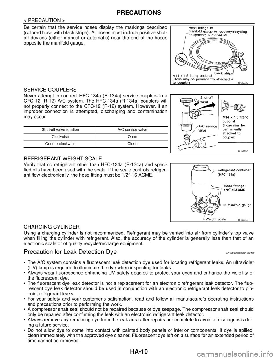
Be certain that the service hoses display the markings described
(colored hose with black stripe). All hoses must include positive shut-
off devices (either manual or automatic) near the end of the hoses
opposite the manifold gauge.
SERVICE COUPLERS
Never attempt to connect HFC-134a (R-134a) service couplers to a
CFC-12 (R-12) A/C system. The HFC-134a (R-134a) couplers will
not properly connect to the CFC-12 (R-12) system. However, if an
improper connection is attempted, discharging and contamination
may occur.
REFRIGERANT WEIGHT SCALE
Verify that no refrigerant other than HFC-134a (R-134a) and speci-
fied oils have been used with the scale. If the scale controls refriger-
ant flow electronically, the hose fitting must be 1/2″-16 ACME.
CHARGING CYLINDER
Using a charging cylinder is not recommended. Refrigerant may be vented into air from cylinder’s top valve
when filling the cylinder with refrigerant. Also, the accuracy of the cylinder is generally less than that of an
electronic scale or of quality recycle/recharge equipment.
Precaution for Leak Detection DyeINFOID:0000000001396435
The A/C system contains a fluorescent leak detection dye used for locating refrigerant leaks. An ultraviolet
(UV) lamp is required to illuminate the dye when inspecting for leaks.
Always wear fluorescence enhancing UV safety goggles to protect your eyes and enhance the visibility of
the fluorescent dye.
The fluorescent dye leak detector is not a replacement for an electronic refrigerant leak detector. The fluo-
rescent dye leak detector should be used in conjunction with an electronic refrigerant leak detector to pin-
point refrigerant leaks.
For your safety and your customer’s satisfaction, read and follow all manufacture’s operating instructions
and precautions prior to performing the work.
A compressor shaft seal should not be repaired because of dye seepage. The compressor shaft seal should
only be repaired after confirming the leak with an electronic refrigerant leak detector.
Always remove any remaining dye from the leak area after repairs are complete to avoid a misdiagnosis dur-
ing a future service.
Do not allow dye to come into contact with painted body panels or interior components. If dye is spilled,
clean immediately with the approved dye cleaner. Fluorescent dye left on a surface for an extended period of
time cannot be removed.
RHA272D
Shut-off valve rotation A/C service valve
Clockwise Open
Counterclockwise Close
RHA273D
RHA274D
Page 3652 of 5883
INL-1
DRIVER CONTROLS
C
D
E
F
G
H
I
J
K
M
SECTION INL
A
B
INL
N
O
P
CONTENTS
INTERIOR LIGHTING SYSTEM
BASIC INSPECTION ....................................2
DIAGNOSIS AND REPAIR WORKFLOW ..........2
Work Flow .................................................................2
FUNCTION DIAGNOSIS ...............................5
INTERIOR ROOM LAMP CONTROL SYSTEM
.....
5
System Diagram ........................................................5
System Description ...................................................5
Component Parts Location ........................................6
Component Description ............................................6
ILLUMINATION CONTROL SYSTEM .................8
System Diagram ........................................................8
System Description ...................................................8
Component Parts Location ........................................8
Component Description .............................................9
DIAGNOSIS SYSTEM (BCM) ............................10
COMMON ITEM .........................................................10
COMMON ITEM : CONSULT-III Function (BCM -
COMMON ITEM) .....................................................
10
INT LAMP ..................................................................10
INT LAMP : CONSULT-III Function (BCM - INT
LAMP) .....................................................................
10
BATTERY SAVER .....................................................12
BATTERY SAVER : CONSULT-III Function (BCM
- BATTERY SAVER) ...............................................
12
COMPONENT DIAGNOSIS .........................14
POWER SUPPLY AND GROUND CIRCUIT ......14
BCM ...........................................................................14
BCM : Diagnosis Procedure ....................................14
INTERIOR ROOM LAMP POWER SUPPLY
CIRCUIT ............................................................
15
Description ...............................................................15
Component Function Check ....................................15
Diagnosis Procedure ...............................................15
INTERIOR ROOM LAMP CONTROL SYSTEM
...
17
Wiring Diagram - INTERIOR ROOM LAMP - ..........17
ILLUMINATION .................................................20
Wiring Diagram - ILLUMINATION - .........................20
ECU DIAGNOSIS .........................................22
BCM (BODY CONTROL MODULE) .................22
Description ...............................................................22
SYMPTOM DIAGNOSIS ..............................23
INTERIOR LIGHTING SYSTEM SYMPTOMS ...23
Symptom Table .......................................................23
PRECAUTION ..............................................24
PRECAUTIONS .................................................24
Supplemental Restraint System (SRS) "AIR BAG"
and "SEAT BELT PRE-TENSIONER" .....................
24
General precautions for service operations .............24
ON-VEHICLE REPAIR .................................25
INTERIOR ROOM LAMP ..................................25
Removal and Installation .........................................25
SERVICE DATA AND SPECIFICATIONS
(SDS) ............................................................
28
SERVICE DATA AND SPECIFICATIONS
(SDS) .................................................................
28
Bulb Specifications ..................................................28
Page 3659 of 5883
INL-8
< FUNCTION DIAGNOSIS >
ILLUMINATION CONTROL SYSTEM
ILLUMINATION CONTROL SYSTEM
System DiagramINFOID:0000000001730918
System DescriptionINFOID:0000000001730919
The illumination lamps operation is dependent upon the position of the lighting switch (combination switch).
When the lighting switch is placed in the 1ST or 2ND position (or if the auto light system is activated) the BCM
(body control module) receives input requesting the parking lamps to illuminate. This input is communicated to
the IPDM E/R (intelligent power distribution module engine room) via the CAN communication lines. The CPU
(central processing unit) of the IPDM E/R controls the tail lamp relay coil. When energized, this relay directs
power to the parking and illumination lamps, which then illuminate.
BATTERY SAVER CONTROL
When the lighting switch (combination switch) is in the 1ST or 2ND position and the ignition switch is turned
from ON or ACC to OFF, the battery saver control feature is activated. Under this condition, the illumination
lamps remain illuminated for 30 minutes unless the lighting switch position is changed. If the lighting switch
position is changed, then the illumination lamps are turned off after a 30 second delay. When the lighting
switch is turned from OFF to 1ST or 2ND position (or if auto light system is activated) after illumination lamps
have been turned off by the battery saver control, the illumination lamps illuminate again.
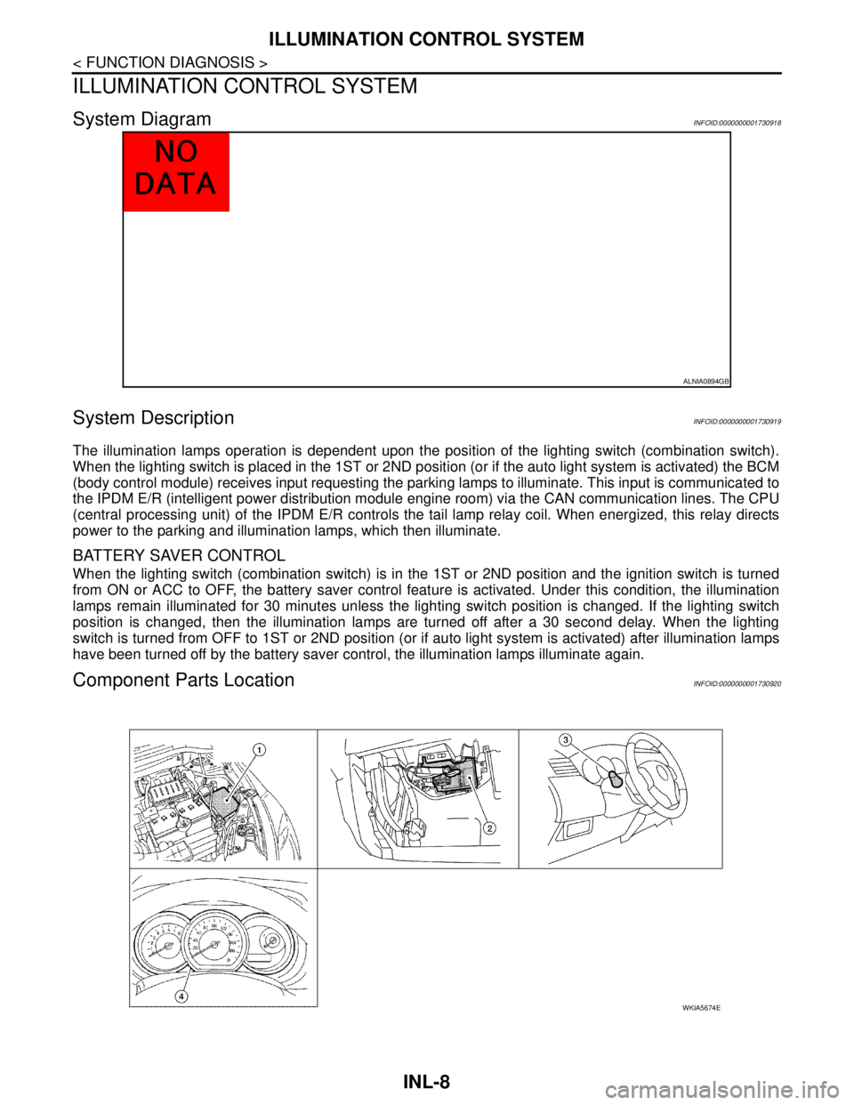
Component Parts LocationINFOID:0000000001730920
ALNIA0894GB
WKIA5674E
Page 3673 of 5883
INL-22
< ECU DIAGNOSIS >
BCM (BODY CONTROL MODULE)
ECU DIAGNOSIS
BCM (BODY CONTROL MODULE)
DescriptionINFOID:0000000001730971
REFERENCE VALUES FOR BCM
For BCM reference values, refer to XX-XX, "*****".
TERMINAL LAYOUT FOR BCM
For the terminal layout for the BCM, refer to XX-XX, "*****".
PHYSICAL VALUES FOR BCM
For physical values for the BCM, refer to XX-XX, "*****".
WIRING DIAGRAM - BCM
For the BCM wiring diagram, refer to XX-XX, "*****".
DTC INSPECTION PRIORITY CHART - BCM
For the BCM DTC inspection priority chart, refer to XX-XX, "*****".
DTC INDEX - BCM
For the BCM DTC index, refer to XX-XX, "*****".
Page 3678 of 5883
INTERIOR ROOM LAMP
INL-27
< ON-VEHICLE REPAIR >
C
D
E
F
G
H
I
J
K
MA
B
INL
N
O
P
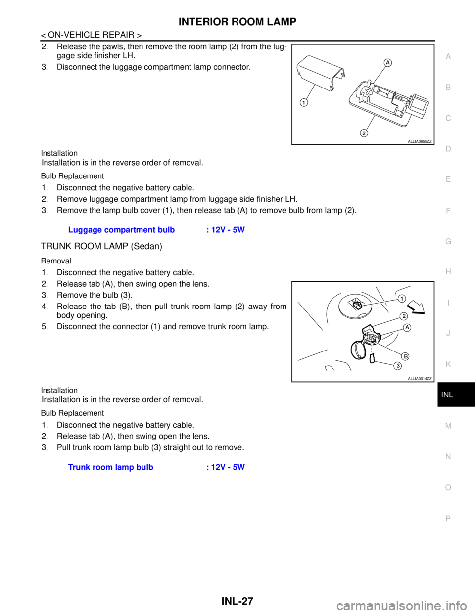
2. Release the pawls, then remove the room lamp (2) from the lug-
gage side finisher LH.
3. Disconnect the luggage compartment lamp connector.
Installation
Installation is in the reverse order of removal.
Bulb Replacement
1. Disconnect the negative battery cable.
2. Remove luggage compartment lamp from luggage side finisher LH.
3. Remove the lamp bulb cover (1), then release tab (A) to remove bulb from lamp (2).
TRUNK ROOM LAMP (Sedan)
Removal
1. Disconnect the negative battery cable.
2. Release tab (A), then swing open the lens.
3. Remove the bulb (3).
4. Release the tab (B), then pull trunk room lamp (2) away from
body opening.
5. Disconnect the connector (1) and remove trunk room lamp.
Installation
Installation is in the reverse order of removal.
Bulb Replacement
1. Disconnect the negative battery cable.
2. Release tab (A), then swing open the lens.
3. Pull trunk room lamp bulb (3) straight out to remove.
ALLIA0655ZZ
Luggage compartment bulb : 12V - 5W
ALLIA0014ZZ
Trunk room lamp bulb : 12V - 5W
Page 3680 of 5883
INT-1
BODY INTERIOR
C
D
E
F
G
H
I
K
L
M
SECTION INT
A
B
INT
N
O
P
CONTENTS
INTERIOR
PRECAUTION ...............................................2
PRECAUTIONS ...................................................2
Precaution for Supplemental Restraint System
(SRS) "AIR BAG" and "SEAT BELT PRE-TEN-
SIONER" ...................................................................
2
Precaution .................................................................2
PREPARATION ............................................3
PREPARATION ...................................................3
Commercial Service Tool ..........................................3
CLIP AND FASTENER ........................................4
Description ................................................................4
SQUEAK AND RATTLE TROUBLE DIAGNO-
SIS .......................................................................
7
Work Flow .................................................................7
Generic Squeak and Rattle Troubleshooting ............9
Diagnostic Worksheet .............................................11
ON-VEHICLE REPAIR .................................13
DOOR FINISHER ...............................................13
Removal and Installation .........................................13
TRUNK LID FINISHER ......................................17
Removal and Installation .........................................17
BACK DOOR TRIM ...........................................18
Removal and Installation .........................................18
BODY SIDE TRIM .............................................19
Component ..............................................................19
Removal and Installation .........................................20
LUGGAGE FLOOR TRIM .................................24
Removal and Installation .........................................24
REAR PARCEL SHELF FINISHER ..................26
Removal and Installation .........................................26
FLOOR TRIM ....................................................27
Removal and Installation .........................................27
HEADLINING ....................................................29
Component ..............................................................29
Removal and Installation - Hatchback .....................31
Removal and Installation - Sedan ............................33
TRUNK ROOM TRIM & TRUNK LID FINISH-
ER ......................................................................
35
Removal and Installation .........................................35
Page 3687 of 5883
INT-8
< PREPARATION >
SQUEAK AND RATTLE TROUBLE DIAGNOSIS
If the noise can be duplicated easily during the test drive, to help identify the source of the noise, try to dupli-
cate the noise with the vehicle stopped by doing one or all of the following:
Close a door.
Tap or push/pull around the area where the noise appears to be coming from.
Rev the engine.
Use a floor jack to recreate vehicle “twist”.
At idle, apply engine load (electrical load, half-clutch on M/T model, drive position on A/T model).
Raise the vehicle on a hoist and hit a tire with a rubber hammer.
Drive the vehicle and attempt to duplicate the conditions the customer states exist when the noise occurs.
If it is difficult to duplicate the noise, drive the vehicle slowly on an undulating or rough road to stress the
vehicle body.
CHECK RELATED SERVICE BULLETINS
After verifying the customer concern or symptom, check ASIST for Technical Service Bulletins (TSBs) related
to that concern or symptom.
If a TSB relates to the symptom, follow the procedure to repair the noise.
LOCATE THE NOISE AND IDENTIFY THE ROOT CAUSE
1. Narrow down the noise to a general area. To help pinpoint the source of the noise, use a listening tool
(Chassis Ear: J-39570, Engine Ear: J-39565 and mechanics stethoscope).
2. Narrow down the noise to a more specific area and identify the cause of the noise by:
Removing the components in the area that you suspect the noise is coming from.
Do not use too much force when removing clips and fasteners, otherwise clips and fasteners
can be broken or lost during the repair, resulting in the creation of new noise.
Tapping or pushing/pulling the component that you suspect is causing the noise.
Do not tap or push/pull the component with excessive force, otherwise the noise will be elimi-
nated only temporarily.
Feeling for a vibration with your hand by touching the component(s) that you suspect is (are) causing
the noise.
Placing a piece of paper between components that you suspect are causing the noise.
Looking for loose components and contact marks.
Refer to INT-9, "
Generic Squeak and Rattle Troubleshooting".
REPAIR THE CAUSE
If the cause is a loose component, tighten the component securely.
If the cause is insufficient clearance between components:
- Separate components by repositioning or loosening and retightening the component, if possible.
- Insulate components with a suitable insulator such as urethane pads, foam blocks, felt cloth tape or ure-
thane tape. A NISSAN Squeak and Rattle Kit (J-43980) is available through your authorized NISSAN Parts
Department.
CAUTION:
Do not use excessive force as many components are constructed of plastic and may be damaged.
Always check with the Parts Department for the latest parts information.
The following materials are contained in the NISSAN Squeak and Rattle Kit (J-43980). Each item can be
ordered separately as needed.
URETHANE PADS [1.5 mm (0.059 in) thick]
Insulates connectors, harness, etc.
76268-9E005: 100 x 135 mm (3.94 x 5.31 in)/76884-71L01: 60 x 85 mm (2.36 x 3.35 in)/76884-71L02: 15 x 25
mm (0.59 x 0.98 in)
INSULATOR (Foam blocks)
Insulates components from contact. Can be used to fill space behind a panel.
73982-9E000: 45 mm (1.77 in) thick, 50 x 50 mm (1.97 x 1.97 in)/73982-50Y00: 10 mm (0.39 in) thick, 50 x 50
mm (1.97 x 1.97 in)
INSULATOR (Light foam block)
80845-71L00: 30 mm (1.18 in) thick, 30 x 50 mm (1.18 x 1.97 in)
FELT CLOTH TAPE
Used to insulate where movement does not occur. Ideal for instrument panel applications.
68370-4B000: 15 x 25 mm (0.59 x 0.98 in) pad/68239-13E00: 5 mm (0.20 in) wide tape roll
The following materials, not found in the kit, can also be used to repair squeaks and rattles.
UHMW (TEFLON) TAPE
Insulates where slight movement is present. Ideal for instrument panel applications.