2007 NISSAN TIIDA Body
[x] Cancel search: BodyPage 3033 of 5883
EXL-32
< COMPONENT DIAGNOSIS >
POWER SUPPLY AND GROUND CIRCUIT
COMPONENT DIAGNOSIS
POWER SUPPLY AND GROUND CIRCUIT
BCM (BODY CONTROL MODULE)
BCM (BODY CONTROL MODULE) : Diagnosis ProcedureINFOID:0000000001523255
For BCM power supply and ground circuit information, refer to XX-XX, "*****".
IPDM E/R (INTELLIGENT POWER DISTRIBUTION MODULE ENGINE ROOM)
IPDM E/R (INTELLIGENT POWER DISTRIBUTION MODULE ENGINE ROOM) : Di-
agnosis Procedure
INFOID:0000000001523256
For IPDM E/R power supply and ground circuit information, refer to XX-XX, "*****" .
Page 3044 of 5883

REAR FOG LAMP CIRCUIT
EXL-43
< COMPONENT DIAGNOSIS >
C
D
E
F
G
H
I
J
K
MA
B
EXL
N
O
P
REAR FOG LAMP CIRCUIT
DescriptionINFOID:0000000001527571
The BCM (Body Control Module) controls power to the rear fog lamps based on inputs from the lighting switch
(combination switch). The BCM sends a request (via CAN communication lines) to the combination meter to
turn the rear fog lamp indicator light ON.
Component Function CheckINFOID:0000000001527572
1.CHECK REAR FOG LAMP OPERATION
CONSULT-III
1. Select "RR FOG LAMP" of BCM active test item.
2. With test items operating, check that the rear fog lamps are turned ON.
Is the rear fog lamp turned ON?
YES >> Rear fog lamp circuit is normal.
NO >> Refer to EXL-43, "
Diagnosis Procedure".
Diagnosis ProcedureINFOID:0000000001527573
HATCHBACK
1.CHECK BCM POWER AND GROUND SUPPLY
Verify BCM power and ground supply. Refer to BCS-30, "
Diagnosis Procedure".
Does BCM have proper power and ground?
YES >> GO TO 2
NO >> Repair harness or connector.
2.CHECK REAR FOG LAMP OUTPUT VOLTAGE
CONSULT-III
1. Turn the ignition switch OFF.
2. Disconnect the rear fog lamp connector B89 and rear combination lamp LH connector B80.
3. Turn the ignition switch ON.
4. Select "RR FOG LAMP" of BCM active test item.
5. With RR FOG LAMP ON, check the voltage between the rear fog lamp connector B89 terminal 1, rear
combination lamp LH connector B80 terminal 2 and ground.
Is battery voltage present?
YES >> GO TO 4
NO >> GO TO 3
3.CHECK REAR FOG LAMP OPEN CIRCUIT
1. Turn the ignition switch OFF.
2. Disconnect BCM connector M20.
3. Check continuity between the BCM harness connector M20 (A) terminal 69 and the rear fog lamp harness
connector B89 (B) terminal 1 and rear combination lamp LH connector B80 (C) terminal 2. ON : Front fog lamp ON
OFF : Front fog lamp OFF
(+)
(−)Voltage
Connector Terminal
B89 1
Ground Battery voltage
B80 2
Page 3072 of 5883
BCM (BODY CONTROL MODULE)
EXL-71
< ECU DIAGNOSIS >
C
D
E
F
G
H
I
J
K
MA
B
EXL
N
O
P
ECU DIAGNOSIS
BCM (BODY CONTROL MODULE)
DescriptionINFOID:0000000001523285
REFERENCE VALUES FOR BCM
For BCM reference values, refer to XX-XX, "*****".
TERMINAL LAYOUT FOR BCM
For the terminal layout for the BCM, refer to XX-XX, "*****".
PHYSICAL VALUES FOR BCM
For physical values for the BCM, refer to XX-XX, "*****".
WIRING DIAGRAM - BCM
For the BCM wiring diagram, refer to XX-XX, "*****".
FAIL SAFE - BCM
For BCM fail safe information, refer to XX-XX, "*****".
DTC INSPECTION PRIORITY CHART - BCM
For the BCM DTC inspection priority chart, refer to XX-XX, "*****".
DTC INDEX - BCM
For the BCM DTC index, refer to XX-XX, "*****".
Page 3105 of 5883
EXT-1
BODY EXTERIOR, DOORS, ROOF & VEHICLE SECURITY
C
D
E
F
G
H
I
J
L
M
SECTION EXT
A
B
EXT
N
O
P
CONTENTS
EXTERIOR
PRECAUTION ...............................................2
PRECAUTIONS ...................................................2
Precaution for Supplemental Restraint System
(SRS) "AIR BAG" and "SEAT BELT PRE-TEN-
SIONER" ...................................................................
2
Precaution .................................................................2
PREPARATION ............................................3
PREPARATION ...................................................3
Special Service Tool .................................................3
Commercial Service Tool ..........................................3
ON-VEHICLE MAINTENANCE .....................4
SQUEAK AND RATTLE TROUBLE DIAGNO-
SIS .......................................................................
4
Work Flow .................................................................4
Generic Squeak and Rattle Troubleshooting ............6
Diagnostic Worksheet ...............................................8
ON-VEHICLE REPAIR .................................10
CLIP AND FASTENER .......................................10
Description ..............................................................10
FRONT BUMPER ...............................................13
Removal and Installation .........................................13
REAR BUMPER ................................................15
Component ..............................................................15
Removal and Installation - Hatchback .....................15
Removal and Installation - Sedan ............................17
FRONT GRILLE ................................................19
Removal and Installation .........................................19
COWL TOP .......................................................20
Removal and Installation .........................................20
FENDER PROTECTOR ....................................22
Component ..............................................................22
Removal and Installation .........................................22
ROOF SIDE MOLDING .....................................23
Component ..............................................................23
Removal and Installation .........................................23
DOOR OUTSIDE MOLDING .............................25
Component ..............................................................25
Removal and Installation .........................................26
CENTER MUD GUARD .....................................28
Removal and Installation .........................................28
TRUNK LID FINISHER ......................................29
Removal and Installation .........................................29
REAR AIR SPOILER .........................................30
Removal and Installation .........................................30
Page 3109 of 5883
SQUEAK AND RATTLE TROUBLE DIAGNOSIS
EXT-5
< ON-VEHICLE MAINTENANCE >
C
D
E
F
G
H
I
J
L
MA
B
EXT
N
O
P
If possible, drive the vehicle with the customer until the noise is duplicated. Note any additional information on
the Diagnostic Worksheet regarding the conditions or location of the noise. This information can be used to
duplicate the same conditions when you confirm the repair.
If the noise can be duplicated easily during the test drive, to help identify the source of the noise, try to dupli-
cate the noise with the vehicle stopped by doing one or all of the following:
Close a door.
Tap or push/pull around the area where the noise appears to be coming from.
Rev the engine.
Use a floor jack to recreate vehicle “twist”.
At idle, apply engine load (electrical load, half-clutch on M/T model, drive position on A/T model).
Raise the vehicle on a hoist and hit a tire with a rubber hammer.
Drive the vehicle and attempt to duplicate the conditions the customer states exist when the noise occurs.
If it is difficult to duplicate the noise, drive the vehicle slowly on an undulating or rough road to stress the
vehicle body.
CHECK RELATED SERVICE BULLETINS
After verifying the customer concern or symptom, check ASIST for Technical Service Bulletins (TSBs) related
to that concern or symptom.
If a TSB relates to the symptom, follow the procedure to repair the noise.
LOCATE THE NOISE AND IDENTIFY THE ROOT CAUSE
1. Narrow down the noise to a general area. To help pinpoint the source of the noise, use a listening tool
(Chassis Ear: J-39570, Engine Ear: J-39565 and mechanics stethoscope).
2. Narrow down the noise to a more specific area and identify the cause of the noise by:
Removing the components in the area that you suspect the noise is coming from.
Do not use too much force when removing clips and fasteners, otherwise clips and fasteners
can be broken or lost during the repair, resulting in the creation of new noise.
Tapping or pushing/pulling the component that you suspect is causing the noise.
Do not tap or push/pull the component with excessive force, otherwise the noise will be elimi-
nated only temporarily.
Feeling for a vibration with your hand by touching the component(s) that you suspect is (are) causing
the noise.
Placing a piece of paper between components that you suspect are causing the noise.
Looking for loose components and contact marks.
Refer to EXT-6, "
Generic Squeak and Rattle Troubleshooting".
REPAIR THE CAUSE
If the cause is a loose component, tighten the component securely.
If the cause is insufficient clearance between components:
- Separate components by repositioning or loosening and retightening the component, if possible.
- Insulate components with a suitable insulator such as urethane pads, foam blocks, felt cloth tape or ure-
thane tape. A Squeak and Rattle Kit is available through your authorized NISSAN Parts Department.
CAUTION:
Do not use excessive force as many components are constructed of plastic and may be damaged.
Always check with the Parts Department for the latest parts information.
The following materials are contained in the Squeak and Rattle Kit. Each item can be ordered separately as
needed.
URETHANE PADS [1.5 mm (0.059 in) thick]
Insulates connectors, harness, etc.
76268-9E005: 100 x 135 mm (3.94 x 5.31 in)/76884-71L01: 60 x 85 mm (2.36 x 3.35 in)/76884-71L02: 15 x 25
mm (0.59 x 0.98 in)
INSULATOR (Foam blocks)
Insulates components from contact. Can be used to fill space behind a panel.
73982-9E000: 45 mm (1.77 in) thick, 50 x 50 mm (1.97 x 1.97 in)/73982-50Y00: 10 mm (0.39 in) thick, 50 x 50
mm (1.97 x 1.97 in)
INSULATOR (Light foam block)
80845-71L00: 30 mm (1.18 in) thick, 30 x 50 mm (1.18 x 1.97 in)
FELT CLOTH TAPE
Used to insulate where movement does not occur. Ideal for instrument panel applications.
68370-4B000: 15 x 25 mm (0.59 x 0.98 in) pad/68239-13E00: 5 mm (0.20 in) wide tape roll
The following materials, not found in the kit, can also be used to repair squeaks and rattles.
Page 3132 of 5883
EXT-28
< ON-VEHICLE REPAIR >
CENTER MUD GUARD
CENTER MUD GUARD
Removal and InstallationINFOID:0000000001568937
REMOVAL
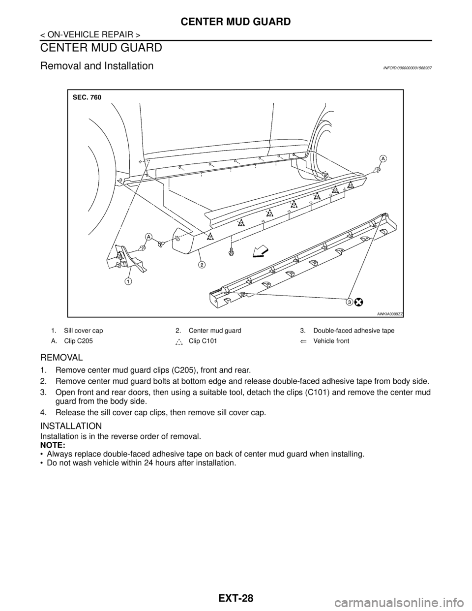
1. Remove center mud guard clips (C205), front and rear.
2. Remove center mud guard bolts at bottom edge and release double-faced adhesive tape from body side.
3. Open front and rear doors, then using a suitable tool, detach the clips (C101) and remove the center mud
guard from the body side.
4. Release the sill cover cap clips, then remove sill cover cap.
INSTALLATION
Installation is in the reverse order of removal.
NOTE:
Always replace double-faced adhesive tape on back of center mud guard when installing.
Do not wash vehicle within 24 hours after installation.
1. Sill cover cap 2. Center mud guard 3. Double-faced adhesive tape
A. Clip C205 Clip C101⇐Vehicle front
AWKIA0099ZZ
Page 3199 of 5883
HOW TO USE THIS MANUAL
GI-5
< HOW TO USE THIS MANUAL >
C
D
E
F
G
H
I
J
K
L
MB
GI
N
O
P
SYMBOLS
How to Follow Trouble DiagnosisINFOID:0000000001606148
DESCRIPTION
NOTICE:
Trouble diagnoses indicate work procedures required to diagnose problems effectively. Observe the following
instructions before diagnosing.
1.Before performing trouble diagnoses, read the “Preliminary Check”, the “Symptom Chart” or the
“Work Flow”.
2.After repairs, re-check that the problem has been completely eliminated.
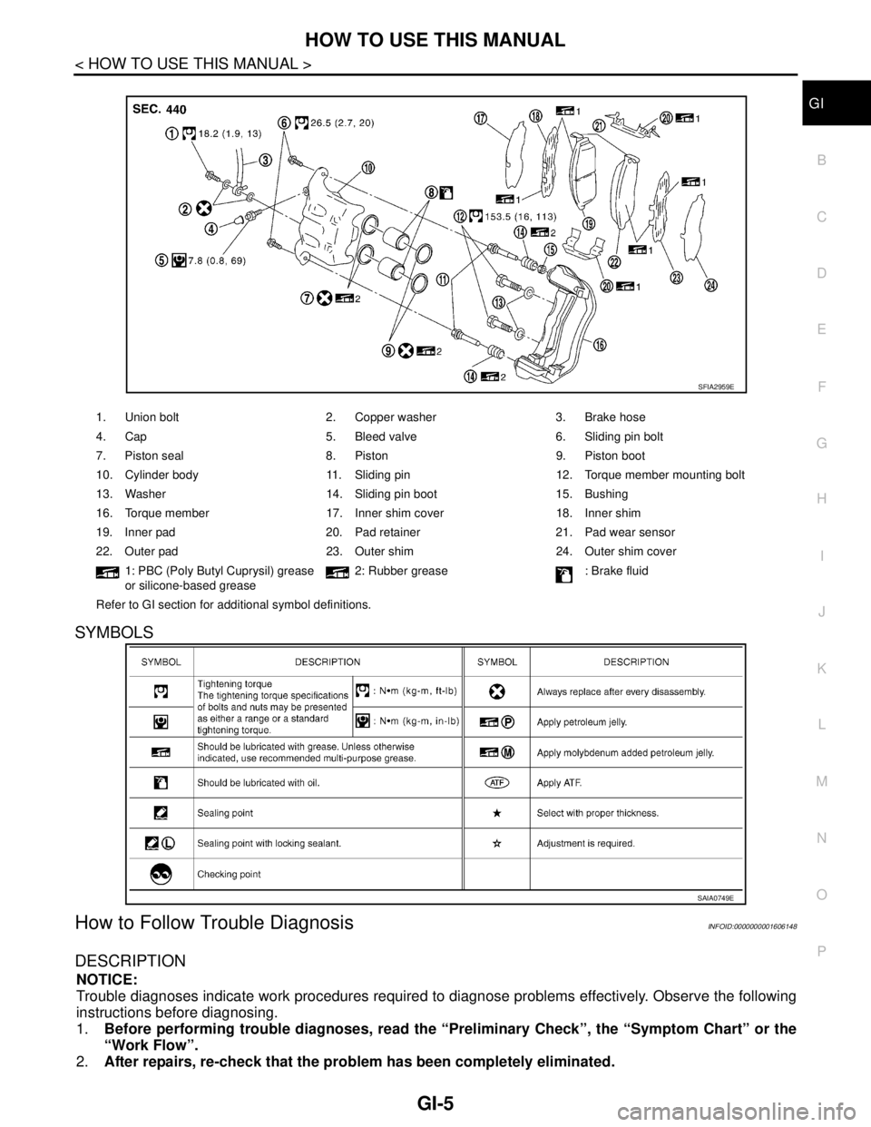
1. Union bolt 2. Copper washer 3. Brake hose
4. Cap 5. Bleed valve 6. Sliding pin bolt
7. Piston seal 8. Piston 9. Piston boot
10. Cylinder body 11. Sliding pin 12. Torque member mounting bolt
13. Washer 14. Sliding pin boot 15. Bushing
16. Torque member 17. Inner shim cover 18. Inner shim
19. Inner pad 20. Pad retainer 21. Pad wear sensor
22. Outer pad 23. Outer shim 24. Outer shim cover
1: PBC (Poly Butyl Cuprysil) grease
or silicone-based grease2: Rubber grease : Brake fluid
Refer to GI section for additional symbol definitions.
SFIA2959E
SAIA0749E
Page 3206 of 5883
GI-12
< HOW TO USE THIS MANUAL >
HOW TO USE THIS MANUAL
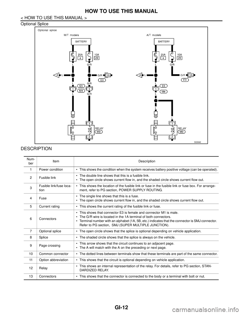
Optional Splice
DESCRIPTION
SGI942
Num-
berItem Description
1 Power condition This shows the condition when the system receives battery positive voltage (can be operated).
2Fusible link The double line shows that this is a fusible link.
The open circle shows current flow in, and the shaded circle shows current flow out.
3Fusible link/fuse loca-
tion This shows the location of the fusible link or fuse in the fusible link or fuse box. For arrange-
ment, refer to PG section, POWER SUPPLY ROUTING.
4Fuse The single line shows that this is a fuse.
The open circle shows current flow in, and the shaded circle shows current flow out.
5 Current rating This shows the current rating of the fusible link or fuse.
6 Connectors This shows that connector E3 is female and connector M1 is male.
The G/R wire is located in the 1A terminal of both connectors.
Terminal number with an alphabet (1A, 5B, etc.) indicates that the connector is SMJ connector.
Refer to PG section, SMJ (SUPER MULTIPLE JUNCTION).
7 Optional splice The open circle shows that the splice is optional depending on vehicle application.
8 Splice The shaded circle shows that the splice is always on the vehicle.
9 Page crossing This arrow shows that the circuit continues to an adjacent page.
The A will match with the A on the preceding or next page.
10 Common connector The dotted lines between terminals show that these terminals are part of the same connector.
11 Option abbreviation This shows that the circuit is optional depending on vehicle application.
12 Relay This shows an internal representation of the relay. For details, refer to PG section, STAN-
DARDIZED RELAY.
13 Connectors This shows that the connector is connected to the body or a terminal with bolt or nut.