Page 3264 of 5883
SQUEAK AND RATTLE TROUBLE DIAGNOSES
GW-5
< SYMPTOM DIAGNOSIS >
C
D
E
F
G
H
I
J
L
MA
B
GW
N
O
P
2. Trunk lid striker out of adjustment
3. The trunk lid torsion bars knocking together
4. A loose license plate or bracket
Most of these incidents can be repaired by adjusting, securing or insulating the item(s) or component(s) caus-
ing the noise.
SUNROOF/HEADLINING
Noises in the sunroof/headlining area can often be traced to one of the following:
1. Sunroof lid, rail, linkage or seals making a rattle or light knocking noise
2. Sun visor shaft shaking in the holder
3. Front or rear windshield touching headliner and squeaking
Again, pressing on the components to stop the noise while duplicating the conditions can isolate most of these
incidents. Repairs usually consist of insulating with felt cloth tape.
OVERHEAD CONSOLE (FRONT AND REAR)
Overhead console noises are often caused by the console panel clips not being engaged correctly. Most of
these incidents are repaired by pushing up on the console at the clip locations until the clips engage.
In addition look for:
1. Loose harness or harness connectors.
2. Front console map/reading lamp lense loose.
3. Loose screws at console attachment points.
SEATS
When isolating seat noise it's important to note the position the seat is in and the load placed on the seat when
the noise is present. These conditions should be duplicated when verifying and isolating the cause of the
noise.
Cause of seat noise include:
1. Headrest rods and holder
2. A squeak between the seat pad cushion and frame
3. The rear seatback lock and bracket
These noises can be isolated by moving or pressing on the suspected components while duplicating the con-
ditions under which the noise occurs. Most of these incidents can be repaired by repositioning the component
or applying urethane tape to the contact area.
UNDERHOOD
Some interior noise may be caused by components under the hood or on the engine wall. The noise is then
transmitted into the passenger compartment.
Causes of transmitted underhood noise include:
1. Any component mounted to the engine wall
2. Components that pass through the engine wall
3. Engine wall mounts and connectors
4. Loose radiator mounting pins
5. Hood bumpers out of adjustment
6. Hood striker out of adjustment
These noises can be difficult to isolate since they cannot be reached from the interior of the vehicle. The best
method is to secure, move or insulate one component at a time and test drive the vehicle. Also, engine RPM
or load can be changed to isolate the noise. Repairs can usually be made by moving, adjusting, securing, or
insulating the component causing the noise.
Page 3269 of 5883
GW-10
< ON-VEHICLE REPAIR >
WINDSHIELD GLASS
ON-VEHICLE REPAIR
WINDSHIELD GLASS
Removal and InstallationINFOID:0000000001716818
REMOVAL
1. Partially remove the headlining (front edge). Refer to INT-31, "Removal and Installation - Hatchback" INT-
33, "Removal and Installation - Sedan".
2. Remove the front wiper arms. Refer to WW-70, "
Removal and Installation".
3. Remove the cowl top cover. Refer to EXT-20, "
Removal and Installation".
4. Disconnect the harness connector of wiper deicer.
5. Apply protective tape around the windshield glass to protect the painted surface from damage.
PIIB6285E
1. Windshield glass assembly 2. Dam sealant 3. Windshield molding
4. Spacer 5. Mirror base 6. Roof panel outer
7. Cowl top front 8. Adhesive 9. Front pillar outer panel
10. Cowl top cover 11. Primer
Page 3278 of 5883
REAR WINDOW GLASS AND MOLDING
GW-19
< ON-VEHICLE REPAIR >
C
D
E
F
G
H
I
J
L
MA
B
GW
N
O
P
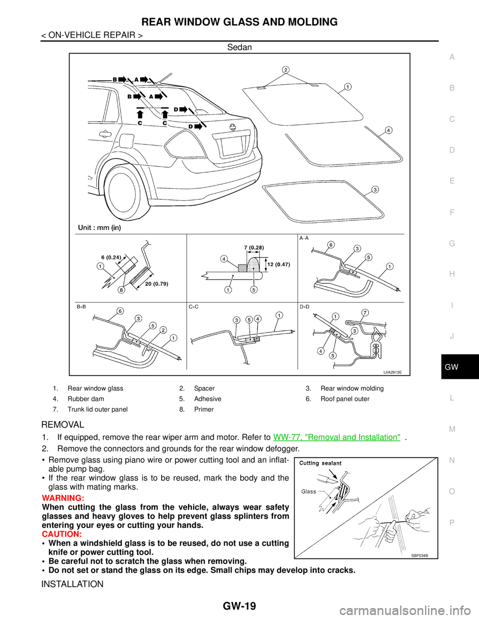
Sedan
REMOVAL
1. If equipped, remove the rear wiper arm and motor. Refer to WW-77, "Removal and Installation" .
2. Remove the connectors and grounds for the rear window defogger.
Remove glass using piano wire or power cutting tool and an inflat-
able pump bag.
If the rear window glass is to be reused, mark the body and the
glass with mating marks.
WARNING:
When cutting the glass from the vehicle, always wear safety
glasses and heavy gloves to help prevent glass splinters from
entering your eyes or cutting your hands.
CAUTION:
When a windshield glass is to be reused, do not use a cutting
knife or power cutting tool.
Be careful not to scratch the glass when removing.
Do not set or stand the glass on its edge. Small chips may develop into cracks.
INSTALLATION
LIIA2913E
1. Rear window glass 2. Spacer 3. Rear window molding
4. Rubber dam 5. Adhesive 6. Roof panel outer
7. Trunk lid outer panel 8. Primer
SBF034B
Page 3689 of 5883
INT-10
< PREPARATION >
SQUEAK AND RATTLE TROUBLE DIAGNOSIS
Most of these incidents can be repaired by adjusting, securing or insulating the item(s) or component(s) caus-
ing the noise.
SUNROOF/HEADLINING
Noises in the sunroof/headlining area can often be traced to one of the following:
1. Sunroof lid, rail, linkage or seals making a rattle or light knocking noise
2. Sun visor shaft shaking in the holder
3. Front or rear windshield touching headliner and squeaking
Again, pressing on the components to stop the noise while duplicating the conditions can isolate most of these
incidents. Repairs usually consist of insulating with felt cloth tape.
OVERHEAD CONSOLE (FRONT AND REAR)
Overhead console noises are often caused by the console panel clips not being engaged correctly. Most of
these incidents are repaired by pushing up on the console at the clip locations until the clips engage.
In addition look for:
1. Loose harness or harness connectors.
2. Front console map/reading lamp lens loose.
3. Loose screws at console attachment points.
SEATS
When isolating seat noise it's important to note the position the seat is in and the load placed on the seat when
the noise is present. These conditions should be duplicated when verifying and isolating the cause of the
noise.
Cause of seat noise include:
1. Headrest rods and holder
2. A squeak between the seat pad cushion and frame
3. The rear seatback lock and bracket
These noises can be isolated by moving or pressing on the suspected components while duplicating the con-
ditions under which the noise occurs. Most of these incidents can be repaired by repositioning the component
or applying urethane tape to the contact area.
UNDERHOOD
Some interior noise may be caused by components under the hood or on the engine wall. The noise is then
transmitted into the passenger compartment.
Causes of transmitted underhood noise include:
1. Any component installed on the engine wall
2. Components that pass through the engine wall
3. Engine wall mounts and connectors
4. Loose radiator pins
5. Hood bumpers out of adjustment
6. Hood striker out of adjustment
These noises can be difficult to isolate since they cannot be reached from the interior of the vehicle. The best
method is to secure, move or insulate one component at a time and test drive the vehicle. Also, engine RPM
or load can be changed to isolate the noise. Repairs can usually be made by moving, adjusting, securing, or
insulating the component causing the noise.
Page 3708 of 5883
HEADLINING
INT-29
< ON-VEHICLE REPAIR >
C
D
E
F
G
H
I
K
L
MA
B
INT
N
O
P
HEADLINING
ComponentINFOID:0000000001329055
LHD Hatchback Models Shown, RHD Similar
LIIA2576E
1. Headlining 2. Assist grip 3. Sunvisor
4. Cap 5. Sunvisor holder 6. Roof console retainer
Page 3709 of 5883
INT-30
< ON-VEHICLE REPAIR >
HEADLINING
LHD Sedan Models Shown, RHD Similar
7. Roof console/map lamp assembly (if
equipped)8. Antenna feeder cable 9. Room lamp
10. Dual lock fastener 11. Room lamp harness 12. Insulator
13. Finisher A. With sunroof B. Without sunroof
Metal clip Clip C103⇐Vehicle front
LIIA2925E
Page 3710 of 5883
HEADLINING
INT-31
< ON-VEHICLE REPAIR >
C
D
E
F
G
H
I
K
L
MA
B
INT
N
O
P
Removal and Installation - HatchbackINFOID:0000000001329056
REMOVAL
1. Remove the negative and positive battery cables.
2. Remove front seat assembly RH/LH. Refer to SE-14, "
Removal and Installation".
3. Remove rear seat cushion and rear seatback. Refer to SE-18, "
Removal and Installation".
4. Remove front seat belt shoulder anchor RH/LH. Refer to SB-6, "
Removal and Installation of Front Seat
Belt".
5. Remove center console body assembly. Refer to IP-11, "
Removal and Installation".
6. Remove front pillar garnish RH/LH. Refer to INT-20, "
Removal and Installation".
7. Remove antenna feeder cable clip, then disconnect antenna
feeder cable connector.
8. Remove front and rear kicking plate inner RH/LH, center pillar lower garnish, center pillar upper garnish,
front and rear body side welt RH/LH. Refer to INT-20, "
Removal and Installation".
WARNING:
Do not reuse center pillar upper garnish if removed.
9. Remove back door weatherstrip. Refer to INT-18, "
Removal and Installation".
10. Release the clips using a suitable tool, then remove the front
and rear assist grips.
11. Remove the sunvisor caps and screws, then remove sunvisor RH/LH.
1. Headlining 2. Assist grip 3. Room lamp
4. Sunvisor 5. Cap 6. Sunvisor holder
7. Map lamp assembly (if equipped) 8. Antenna feeder cable 9. Roof console assembly (if
equipped)
10. Roof plate (if equipped) 11. Dual lock fastener 12. Insulator
13. Room lamp harness 14. Cover A. With sunroof
B. Without sunroof Clip C103⇐Vehicle front
PIIB2583J
PIIB2584J
Page 3711 of 5883
INT-32
< ON-VEHICLE REPAIR >
HEADLINING
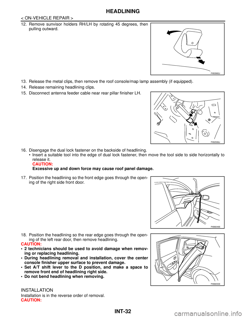
12. Remove sunvisor holders RH/LH by rotating 45 degrees, then
pulling outward.
13. Release the metal clips, then remove the roof console/map lamp assembly (if equipped).
14. Release remaining headlining clips.
15. Disconnect antenna feeder cable near rear pillar finisher LH.
16. Disengage the dual lock fastener on the backside of headlining.
Insert a suitable tool into the edge of dual lock fastener, then move the tool side to side horizontally to
release it.
CAUTION:
Excessive up and down force may cause roof panel damage.
17. Position the headlining so the front edge goes through the open-
ing of the right side front door.
18. Position the headlining so the rear edge goes through the open-
ing of the left rear door, then remove headlining.
CAUTION:
2 technicians should be used to avoid damage when remov-
ing or replacing headlining.
During headlining removal and installation, cover the center
console finisher upper surface to prevent damage.
Set A/T shift lever to the D position, and make a space to
remove front end of headlining right side.
Do not bend headlining when removing.
INSTALLATION
Installation is in the reverse order of removal.
CAUTION:
PIIB3982J
PIIB2586J
PIIB6049E
PIIB6050E