2007 NISSAN TIIDA drain bolt
[x] Cancel search: drain boltPage 4263 of 5883
ENGINE MAINTENANCE (HR16DE)
MA-23
< ON-VEHICLE MAINTENANCE >
C
D
E
F
G
H
I
J
K
L
MB
MAN
OA
When the lock nut is loosened excessively, the idler pulley tilts and the correct tension adjust-
ment cannot be performed. Never loosen it excessively (more than 45 degrees).
Put a matching mark on the lock nut, and check turning angle with a protractor. Never visually
check the tightening angle.
2. Adjust the belt tension by turning the adjusting bolt.
CAUTION:
When checking immediately after installation, first adjust it to the specified value. Then, after
turning crankshaft two turns or more, re-adjust to the specified value to avoid variation in deflec-
tion between pulleys.
When the tension adjustment is performed, the lock nut should be in the condition at step“2”. If
the tension adjustment is performed when the lock nut is loosened more than the standard, the
idler pulley tilts and the correct tension adjustment cannot be performed.
3. Tighten the idler pulley lock nut.
ENGINE COOLANT
ENGINE COOLANT : InspectionINFOID:0000000001730856
LEVEL CHECK
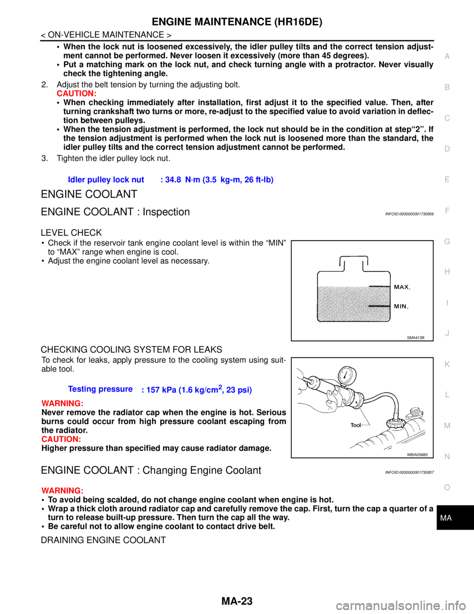
Check if the reservoir tank engine coolant level is within the “MIN”
to “MAX” range when engine is cool.
Adjust the engine coolant level as necessary.
CHECKING COOLING SYSTEM FOR LEAKS
To check for leaks, apply pressure to the cooling system using suit-
able tool.
WARNING:
Never remove the radiator cap when the engine is hot. Serious
burns could occur from high pressure coolant escaping from
the radiator.
CAUTION:
Higher pressure than specified may cause radiator damage.
ENGINE COOLANT : Changing Engine CoolantINFOID:0000000001730857
WARNING:
To avoid being scalded, do not change engine coolant when engine is hot.
Wrap a thick cloth around radiator cap and carefully remove the cap. First, turn the cap a quarter of a
turn to release built-up pressure. Then turn the cap all the way.
Be careful not to allow engine coolant to contact drive belt.
DRAINING ENGINE COOLANT
Idler pulley lock nut : 34.8 N·m (3.5 kg-m, 26 ft-lb)
SMA412B
Testing pressure
: 157 kPa (1.6 kg/cm2, 23 psi)
WBIA0568E
Page 4566 of 5883
RF-32
< ON-VEHICLE REPAIR >
SUNROOF SYSTEM
1. Remove headlining. Refer to INT-29, "Component".
2. Visually check drain hoses for:
Proper connection at sunroof unit assembly.
Damage, pinch, cracks, deterioration.
Proper fastening and routing on body panels.
3. Pour water through drain hoses to determine watertight performance.
If a damaged or leaking portion in any drain hose is found, replace entire drain hose as an assembly.
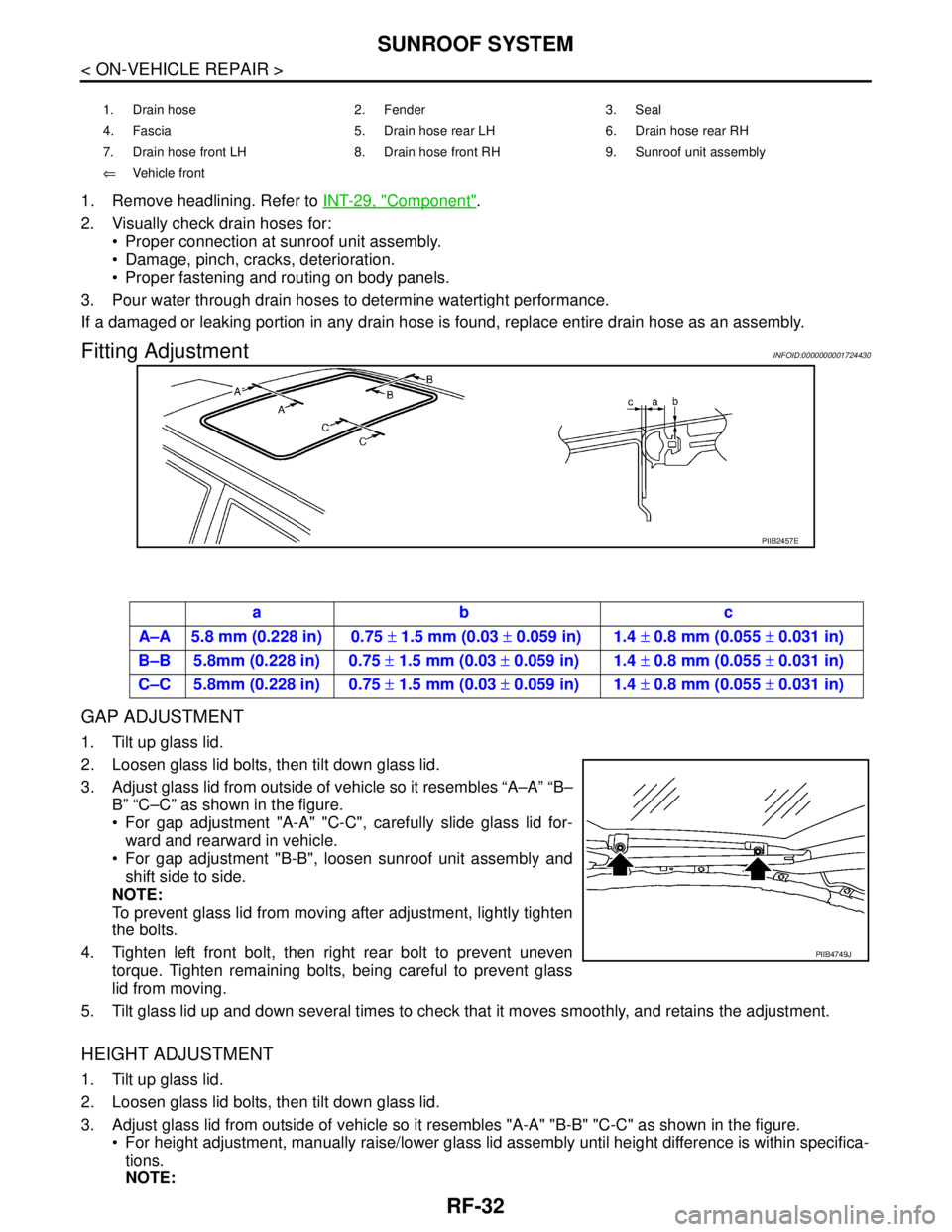
Fitting AdjustmentINFOID:0000000001724430
GAP ADJUSTMENT
1. Tilt up glass lid.
2. Loosen glass lid bolts, then tilt down glass lid.
3. Adjust glass lid from outside of vehicle so it resembles “A–A” “B–
B” “C–C” as shown in the figure.
For gap adjustment "A-A" "C-C", carefully slide glass lid for-
ward and rearward in vehicle.
For gap adjustment "B-B", loosen sunroof unit assembly and
shift side to side.
NOTE:
To prevent glass lid from moving after adjustment, lightly tighten
the bolts.
4. Tighten left front bolt, then right rear bolt to prevent uneven
torque. Tighten remaining bolts, being careful to prevent glass
lid from moving.
5. Tilt glass lid up and down several times to check that it moves smoothly, and retains the adjustment.
HEIGHT ADJUSTMENT
1. Tilt up glass lid.
2. Loosen glass lid bolts, then tilt down glass lid.
3. Adjust glass lid from outside of vehicle so it resembles "A-A" "B-B" "C-C" as shown in the figure.
For height adjustment, manually raise/lower glass lid assembly until height difference is within specifica-
tions.
NOTE:
1. Drain hose 2. Fender 3. Seal
4. Fascia 5. Drain hose rear LH 6. Drain hose rear RH
7. Drain hose front LH 8. Drain hose front RH 9. Sunroof unit assembly
⇐Vehicle front
PIIB2457E
ab c
A–A 5.8 mm (0.228 in) 0.75 ± 1.5 mm (0.03 ± 0.059 in) 1.4 ± 0.8 mm (0.055 ± 0.031 in)
B–B 5.8mm (0.228 in) 0.75 ± 1.5 mm (0.03 ± 0.059 in) 1.4 ± 0.8 mm (0.055 ± 0.031 in)
C–C 5.8mm (0.228 in) 0.75 ± 1.5 mm (0.03 ± 0.059 in) 1.4 ± 0.8 mm (0.055 ± 0.031 in)
PIIB4749J
Page 4569 of 5883
SUNROOF SYSTEM
RF-35
< ON-VEHICLE REPAIR >
C
D
E
F
G
H
I
J
L
MA
B
RF
N
O
P
Removal and InstallationINFOID:0000000001724429
CAUTION:
After installation or any adjustment, check clearances for sunroof operation and glass lid alignment.
Handle glass lid with care to prevent damage.
Fully close the glass lid before removal, then do not operate sunroof motor assembly after removal.
When removing sunroof unit assembly, use shop cloths to protect the seats and trim from damage.
Always work with a helper.
NOTE:
For easy installation, mark each point before removal.
SUNROOF UNIT ASSEMBLY
Removal
1. Tilt glass lid up, then remove. Refer to RF-35, "Removal and Installation".
2. Position sunroof unit assembly to the fully closed position.
3. Remove the headlining. Refer to INT-29, "
Component".
4. Disconnect drain hoses.
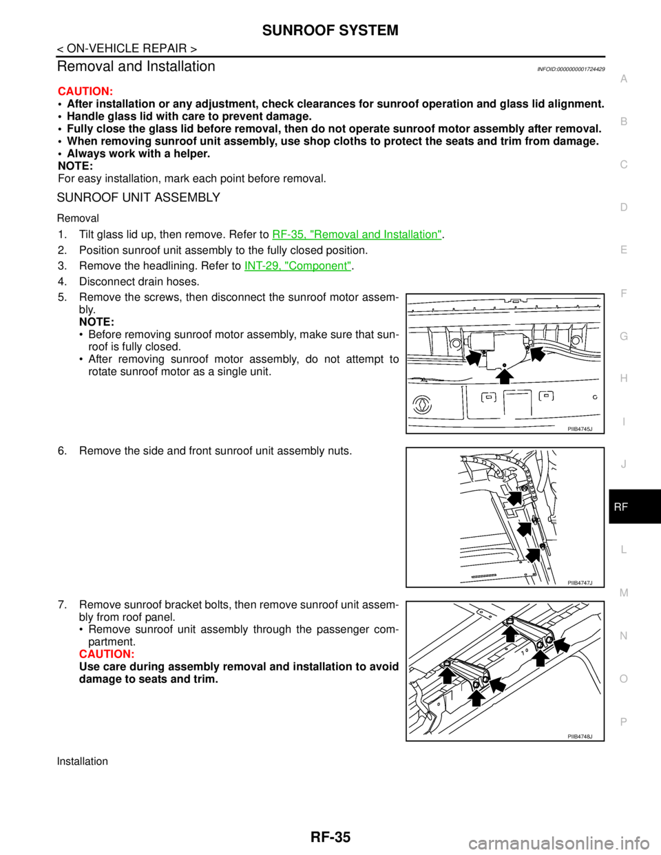
5. Remove the screws, then disconnect the sunroof motor assem-
bly.
NOTE:
Before removing sunroof motor assembly, make sure that sun-
roof is fully closed.
After removing sunroof motor assembly, do not attempt to
rotate sunroof motor as a single unit.
6. Remove the side and front sunroof unit assembly nuts.
7. Remove sunroof bracket bolts, then remove sunroof unit assem-
bly from roof panel.
Remove sunroof unit assembly through the passenger com-
partment.
CAUTION:
Use care during assembly removal and installation to avoid
damage to seats and trim.
Installation
PIIB4745J
PIIB4747J
PIIB4748J
Page 4570 of 5883
RF-36
< ON-VEHICLE REPAIR >
SUNROOF SYSTEM
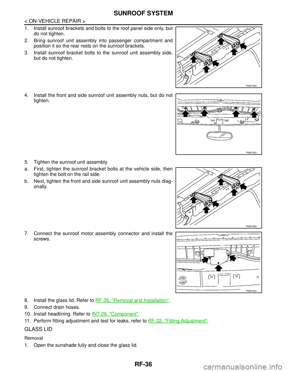
1. Install sunroof brackets and bolts to the roof panel side only, but
do not tighten.
2. Bring sunroof unit assembly into passenger compartment and
position it so the rear rests on the sunroof brackets.
3. Install sunroof bracket bolts to the sunroof unit assembly side,
but do not tighten.
4. Install the front and side sunroof unit assembly nuts, but do not
tighten.
5. Tighten the sunroof unit assembly.
a. First, tighten the sunroof bracket bolts at the vehicle side, then
tighten the bolt on the rail side.
b. Next, tighten the front and side sunroof unit assembly nuts diag-
onally.
6.7. Connect the sunroof motor assembly connector and install the
screws.
8. Install the glass lid. Refer to RF-35, "
Removal and Installation".
9. Connect drain hoses.
10. Install headlining. Refer to INT-29, "
Component".
11. Perform fitting adjustment and test for leaks, refer to RF-32, "
Fitting Adjustment".
GLASS LID
Removal
1. Open the sunshade fully and close the glass lid.
PIIB4748J
PIIB4746J
PIIB4748J
PIIB4745J
Page 5111 of 5883

PRECAUTIONS
TM-165
< PRECAUTION >[TYPE 1 (4AT: RE4F03B)]
C
E
F
G
H
I
J
K
L
MA
B
TM
N
O
P
Before assembly, apply a coat of recommended ATF to all parts. Apply petroleum jelly to protect O-rings and
seals, or hold bearings and washers in place during assembly. Do not use grease.
Extreme care should be taken to avoid damage to O-rings, seals and gaskets when assembling.
After overhaul, refill the A/T with new ATF.
When the A/T drain plug is removed, only some of the fluid is drained. Old A/T fluid will remain in torque con-
verter and ATF cooling system.
Always follow the procedures under “Changing A/T Fluid” in the AT section when changing A/T fluid. Refer to
XX-XX, "*****"
, XX-XX, "*****".
Service Notice or PrecautionINFOID:0000000001696268
TORQUE CONVERTER SERVICE
The torque converter should be replaced under any of the following conditions:
External leaks in the hub weld area.
Converter hub is scored or damaged.
Converter pilot is broken, damaged or fits poorly into crankshaft.
Steel particles are found after flushing the cooler and cooler lines.
Pump is damaged or steel particles are found in the converter.
Vehicle has TCC shudder and/or no TCC apply. Replace only after all hydraulic and electrical diagnoses
have been made. (Converter clutch material may be glazed.)
Converter is contaminated with engine coolant containing antifreeze.
Internal malfunction of stator roller clutch.
Heavy clutch debris due to overheating (blue converter).
Steel particles or clutch lining material found in fluid filter or on magnet when no internal parts in unit are
worn or damaged — indicates that lining material came from converter.
The torque converter should not be replaced if:
The fluid has an odor, is discolored, and there is no evidence of metal or clutch facing particles.
The threads in one or more of the converter bolt holes are damaged.
A/T malfunction did not display evidence of damaged or worn internal parts, steel particles or clutch plate lin-
ing material in unit and inside the fluid filter.
Vehicle has been exposed to high mileage (only). The exception may be where the torque converter clutch
dampener plate lining has seen excess wear by vehicles operated in heavy and/or constant traffic, such as
taxi, delivery or police use.
OBD SELF-DIAGNOSIS (FOR TYPE 1 ONLY)
A/T self-diagnosis is performed by the TCM in combination with the ECM. The results can be read through
the blinking pattern of the OD OFF indicator lamp or the malfunction indicator lamp (MIL). Refer to the table
on XX-XX, "*****"
for the indicator used to display each self-diagnostic result.
The self-diagnostic results indicated by the MIL are automatically stored in both the ECM and TCM memo-
ries.
Always perform the procedure “HOW TO ERASE DTC” on XX-XX, "*****"
to complete the repair and
avoid unnecessary blinking of the MIL.
The following self-diagnostic items can be detected using ECM self-diagnostic results mode* only when the
OD OFF indicator lamp does not indicate any malfunctions.
-PNP switch
- A/T 1st, 2nd, 3rd, or 4th gear function
*: For details of OBD, refer to XX-XX, "*****"
.
Wiring Diagram and Trouble DiagnosisINFOID:0000000001696269
When reading wiring diagrams, refer to the following:
XX-XX, "*****"
XX-XX, "*****"
When performing trouble diagnosis, refer to the following:
XX-XX, "*****"
XX-XX, "*****"
Page 5137 of 5883

CONTROL SYSTEM
TM-191
< ON-VEHICLE REPAIR >[TYPE 1 (4AT: RE4F03B)]
C
E
F
G
H
I
J
K
L
MA
B
TM
N
O
P
CONTROL SYSTEM
Control Valve Assembly and AccumulatorsINFOID:0000000001733158
COMPONENTS
REMOVAL
Refer to the figure for control valve assembly and accumulators removal procedure.
CAUTION:
Do not drop manual valve and servo release accumulator
return spring.
1. A/T 2. O-ring 3. Return spring
4. Control valve assembly 5. Oil pan gasket 6. Oil pan
7. Drain plug gasket 8. Drain plug 9. Magnet
10. Oil pan fitting bolt 11. Snap ring 12. O-ring
13. Servo release accumulator piston 14. N-D accumulator piston 15. O-ring
16. Return spring 17. Lip seal
SCIA6216J
SCIA3150E
Page 5164 of 5883

TM-218
< DISASSEMBLY AND ASSEMBLY >[TYPE 1 (4AT: RE4F03B)]
OVERHAUL
19. Oil pan gasket 20. Oil pan 21. Drain plug gasket
22. Drain plug 23. Magnet 24. Oil pan fitting bolt
25. Snap ring 26. O-ring 27. O-ring
28. N-D accumulator piston 29. Return spring 30. O-ring
31. Lip seal 32. Turbine revolution sensor (power
train revolution sensor)33. O-ring
34. Retaining pin 35. Detent spring 36. Retaining pin
37. Manual shaft 38. Manual shaft oil seal 39. Manual plate
40. Parking rod plate 41. Parking rod 42. OD servo piston retainer
43. Snap ring 44. O-ring 45. OD servo piston
46. D-ring 47. Servo piston retainer 48. O-ring
49. E-ring 50. Spring retainer 51. OD servo return spring
52. D-ring 53. Band servo piston 54. Band servo thrust washer
55. Band servo piston stem 56. 2nd servo return spring 57. PNP switch
58. Parking shaft 59. Return spring 60. Output gear adjusting spacer
61. Output gear bearing 62. Output gear 63. Side cover gasket
64. Side cover 65. Side cover fitting bolt 66. Lock nut
67. Idler gear 68. Idler gear bearing 69. Reduction pinion gear adjusting
shim
70. Parking actuator support 71. Parking pawl 72. LH differential side oil seal
73. Revolution sensor
: Apply locking sealant (Loctite #518).
Page 5263 of 5883

ASSEMBLY
TM-317
< DISASSEMBLY AND ASSEMBLY >[TYPE 1 (4AT: RE4F03B)]
C
E
F
G
H
I
J
K
L
MA
B
TM
N
O
P
b. Install oil pan gasket on transaxle case.
CAUTION:
Completely remove all moisture, oil and old gasket, etc.
from the oil pan gasket mounting surface of transaxle
case.
Do not reuse oil pan gasket.
c. Install oil pan on transaxle case.
CAUTION:
Completely remove all moisture, oil and old gasket, etc.
from the oil pan gasket mounting surface of oil pan.
d. Tighten oil pan bolts (1) to the specified torque.
CAUTION:
Always replace oil pan bolts (1) as they are self-sealing bolts.
Tighten four bolts in a criss-cross pattern to prevent dislocation of gasket.
e. Install drain plug gasket and drain plug (2) to oil pan.
CAUTION:
Do not reuse drain plug gasket.
f. Tighten drain plug to the specified torque.
32. Install PNP switch (2) on transaxle case.
: Bolt (3)
a. Set manual shaft (1) in “P” position.
b. Temporarily install PNP switch (2) on manual shaft (1).
c. Set manual shaft (1) in “N” position.
d. Use a 4 mm (0.16 in) dia. pin for this adjustment.
i. Insert the pin straight into the manual shaft (1) adjustment hole.
ii. Rotate PNP switch (2) until the pin can also be inserted straight
into hole in PNP switch (2).
e. Tighten PNP switch fitting bolts to the specified torque.
f. Remove pin from adjustment hole after adjusting PNP switch (2).
33. Install O-ring (3) to turbine revolution sensor (power train revolu-
tion sensor) (1).
34. Install turbine revolution sensor (power train revolution sensor)
(1) to transaxle case (2).
: Bolt
35. Tighten turbine revolution sensor (power train revolution sensor)
bolt to the specified torque.
36. Install revolution sensor (1) to transaxle case (2).
37. Tighten revolution sensor bolts to the specified torque.
: Bolt
CAUTION:
SCIA6050J
SCIA5904J
SCIA7004J
SCIA7170J