2007 NISSAN TIIDA br-24
[x] Cancel search: br-24Page 201 of 5883

BRAKE FLUID
BR-9
< ON-VEHICLE MAINTENANCE >
C
D
E
G
H
I
J
K
L
MA
B
BR
N
O
P
3. With brake pedal depressed, loosen bleed valve to let the air out, and then tighten it immediately.
4. Repeat steps 2, 3 until no more air comes out.
5. Tighten bleed valve to specified torque. Refer to BR-24, "
Component" (front disc brake), BR-27, "Compo-
nent" (rear drum brake).
6. Following the steps 1 to 5 above, with master cylinder reservoir tank filled at least half way, bleed air from
the rear right, front left, rear left, and front right brake, in that order.
Page 216 of 5883
BR-24
< ON-VEHICLE REPAIR >
FRONT DISC BRAKE
FRONT DISC BRAKE
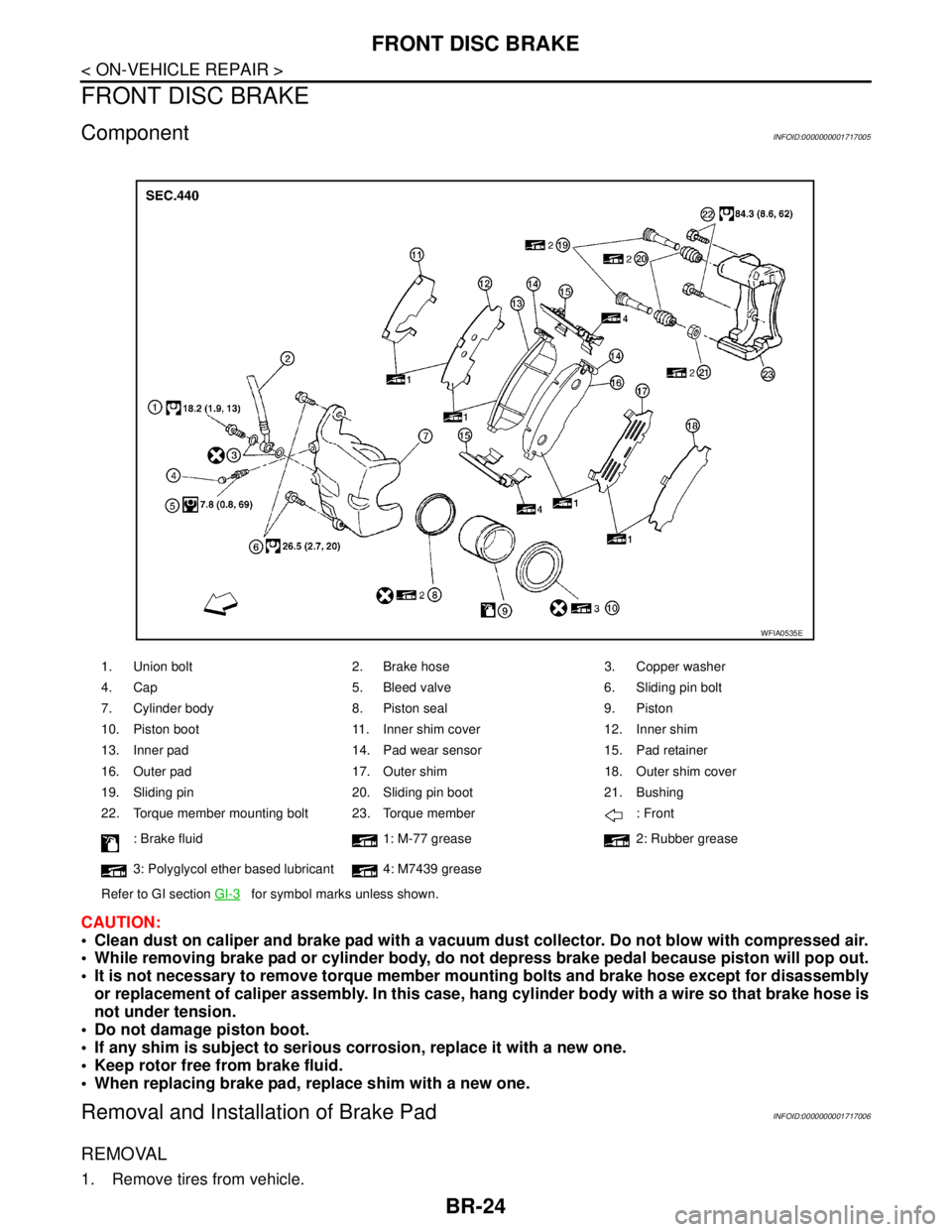
ComponentINFOID:0000000001717005
CAUTION:
Clean dust on caliper and brake pad with a vacuum dust collector. Do not blow with compressed air.
While removing brake pad or cylinder body, do not depress brake pedal because piston will pop out.
It is not necessary to remove torque member mounting bolts and brake hose except for disassembly
or replacement of caliper assembly. In this case, hang cylinder body with a wire so that brake hose is
not under tension.
Do not damage piston boot.
If any shim is subject to serious corrosion, replace it with a new one.
Keep rotor free from brake fluid.
When replacing brake pad, replace shim with a new one.
Removal and Installation of Brake PadINFOID:0000000001717006
REMOVAL
1. Remove tires from vehicle.
1. Union bolt 2. Brake hose 3. Copper washer
4. Cap 5. Bleed valve 6. Sliding pin bolt
7. Cylinder body 8. Piston seal 9. Piston
10. Piston boot 11. Inner shim cover 12. Inner shim
13. Inner pad 14. Pad wear sensor 15. Pad retainer
16. Outer pad 17. Outer shim 18. Outer shim cover
19. Sliding pin 20. Sliding pin boot 21. Bushing
22. Torque member mounting bolt 23. Torque member : Front
: Brake fluid 1: M-77 grease 2: Rubber grease
3: Polyglycol ether based lubricant 4: M7439 grease
Refer to GI section GI-3
for symbol marks unless shown.
WFIA0535E
Page 217 of 5883

FRONT DISC BRAKE
BR-25
< ON-VEHICLE REPAIR >
C
D
E
G
H
I
J
K
L
MA
B
BR
N
O
P
2. Remove sliding pin bolt (lower side).
3. Hang cylinder body with a wire, and remove pads, shims and
pad retainers from torque member.
CAUTION:
When removing pad retainer from torque member, lift pad
retainer in the direction shown by arrow, so as not to
deform it.
INSTALLATION
1. Apply M-77 grease or equivalent to the shims. Install shims to pads.
CAUTION:
Securely install shims according to mounting direction of pads.
2. Apply M7439 grease or equivalent to pad contact surface on pad retainers. Install pad retainers and pads
to the torque member.
CAUTION:
When installing pad retainer, attach it firmly so that it is
not lifted up from torque member, as shown.
3. Install cylinder body to torque member.
NOTE:
Use a disc brake piston tool (commercial service tool) to easily press to piston in.
CAUTION:
Check the brake fluid level in the reservoir tank for fluid level because brake fluid returns to mas-
ter cylinder reservoir tank when pressing piston in.
4. Install lower sliding pin bolt (lower side), and tighten it to the specified torque. Refer to BR-24, "
Compo-
nent" .
5. Check brake for drag.
6. Install tires to the vehicle.
Removal and Installation of Brake Caliper AssemblyINFOID:0000000001717007
REMOVAL
1. Remove tires from vehicle.
2. Secure disc rotor using wheel nuts.
CAUTION:
Put matching marks on wheel hub assembly and disc rotor, if it is necessary to remove disc rotor.
3. Drain brake fluid. Refer to BR-8, "
Drain and Refill" .
SBR556E
PFIA0273E
Page 218 of 5883

BR-26
< ON-VEHICLE REPAIR >
FRONT DISC BRAKE
4. Remove union bolt, and then remove brake hose from caliper
assembly.
5. Remove torque member mounting bolts from torque member,
and remove caliper assembly from vehicle.
INSTALLATION
1. Install caliper assembly to vehicle, and tighten mounting bolts to the specified torque. Refer to BR-24,
"Component" .
CAUTION:
Before installing torque member to vehicle, wipe oil and grease on mounting surface of steering
knuckle and torque member.
2. Install brake hose to caliper assembly. Refer to BR-14, "
Hydraulic Circuit" .
3. Refill with new brake fluid and bleed air. Refer to BR-8, "
Bleeding Brake System" .
4. Check front disc brake for drag.
5. Install tires to the vehicle.
Brake BurnishingINFOID:0000000001717009
Burnish the new braking surfaces according to following procedure after refinishing or replacing disc rotors,
pads, or if a soft pedal occurs at very low mileage.
CAUTION:
Be careful of vehicle speed because brake does not operate easily until pad and disc rotor are
securely fitted.
Only perform this procedure under safe road and traffic conditions. Use extreme caution.
1. Drive vehicle on straight, flat road.
2. Depress brake pedal with the power to stop vehicle within 3 to 5 seconds until the vehicle stops.
3. Drive without depressing brake pedal for a few minutes to cool brake.
4. Repeat steps 1 to 3 until pad and disc rotor are securely fitted.
WFIA0524E
Page 227 of 5883

FRONT DISC BRAKE
BR-35
< DISASSEMBLY AND ASSEMBLY >
C
D
E
G
H
I
J
K
L
MA
B
BR
N
O
P
Check sliding pins, sliding pin bolts and sliding pin boots for wear, damage, and cracks. Replace applicable
part as necessary.
ASSEMBLY
CAUTION:
When assembling, use only specified rubber lubricant.
1. Apply polyglycol ether based lubricant to new piston seal and
install them to cylinder body.
2. Apply rubber grease to piston boot and apply brake fluid to pis-
ton. Cover the piston end with piston boot, and install cylinder-
side lip on piston boot properly into groove on cylinder body.
3. Press piston into cylinder body by hand to assemble piston-side
lip on piston boot properly into a groove on piston.
CAUTION:
Press piston evenly and change pressing point to prevent
inner wall of cylinder from being rubbed.
4. Install sliding pins and sliding pin boots to the torque member.
5. If pads, shims and pad retainers were removed, install them to torque member. Refer to BR-24, "
Removal
and Installation of Brake Pad" .
6. Install cylinder body to torque member.
7. Install sliding pin bolts.
8. Install caliper assembly to vehicle. Refer to BR-25, "
Removal and Installation of Brake Caliper Assembly"
.
9. Tighten sliding pin bolts to specified torque. Refer to BR-24, "
Component" .
DISC ROTOR INSPECTION
Visual Inspection
Check surfaces of disc rotor for uneven wear, cracks, and serious damage. Replace applicable part as neces-
sary.
Runout Inspection
1. Using wheel nuts, secure disc rotor to wheels hub 2 or more positions.
SFIA2278E
SFIA3074E
SFIA2279E
Page 2738 of 5883
![NISSAN TIIDA 2007 Service Repair Manual ENGINE ASSEMBLY
EM-91
< REMOVAL AND INSTALLATION >[HR16DE]
C
D
E
F
G
H
I
J
K
L
MA
EM
N
P O Vehicle Underbody
1. Remove front wheel sensor (LH and RH) for ABS from steering knuckle. Refer to BRC-83, "R](/manual-img/5/57395/w960_57395-2737.png "NISSAN TIIDA 2007 Service Repair Manual ENGINE ASSEMBLY
EM-91
< REMOVAL AND INSTALLATION >[HR16DE]
C
D
E
F
G
H
I
J
K
L
MA
EM
N
P O Vehicle Underbody
1. Remove front wheel sensor (LH and RH) for ABS from steering knuckle. Refer to BRC-83, \"R")
ENGINE ASSEMBLY
EM-91
< REMOVAL AND INSTALLATION >[HR16DE]
C
D
E
F
G
H
I
J
K
L
MA
EM
N
P O Vehicle Underbody
1. Remove front wheel sensor (LH and RH) for ABS from steering knuckle. Refer to BRC-83, "Removal and
Installation".
2. Remove brake caliper assembly with piping connected from steering knuckle. Temporarily secure it on the
vehicle side with a rope to avoid load on it. Refer to BR-24, "
Component".
3. Remove drive shafts (LH and RH) from steering knuckle. Refer to FAX-7, "
Removal and Installation".
4. Remove exhaust front tube. Refer to EX-5, "
Component".
5. Remove rear torque rod.
NOTE:
A/T models shown.
6. Remove A/T cooler hoses from transmission (A/T models).
7. Preparation for the separation work of transaxle is as follows:
Remove transaxle joint bolts which pierce at oil pan (upper) lower rear side. Refer to EM-89, "
Exploded
View".
Removal
1. Install engine slinger to cylinder head front left side (A) and rear
right side (B) and support the engine with a hoist.
2. Lift with a hoist and secure the engine in appropriate position.
3. Use a suitable tool to securely support bottom of the engine and
the transaxle assembly and simultaneously adjust hoist tension.
CAUTION:
Put a piece of wood or something similar as the supporting
surface, secure a completely stable condition.
PBIC3737E
PBIC3738E
PBIC3223J
Page 4296 of 5883
MA-56
< ON-VEHICLE MAINTENANCE >
CHASSIS AND BODY MAINTENANCE
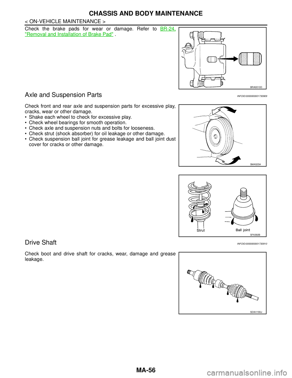
Check the brake pads for wear or damage. Refer to BR-24,
"Removal and Installation of Brake Pad" .
Axle and Suspension PartsINFOID:0000000001730909
Check front and rear axle and suspension parts for excessive play,
cracks, wear or other damage.
Shake each wheel to check for excessive play.
Check wheel bearings for smooth operation.
Check axle and suspension nuts and bolts for looseness.
Check strut (shock absorber) for oil leakage or other damage.
Check suspension ball joint for grease leakage and ball joint dust
cover for cracks or other damage.
Drive ShaftINFOID:0000000001730910
Check boot and drive shaft for cracks, wear, damage and grease
leakage.
BRA0010D
SMA525A
SFA392B
SDIA1190J