2007 NISSAN TIIDA drain bolt
[x] Cancel search: drain boltPage 5264 of 5883
TM-318
< DISASSEMBLY AND ASSEMBLY >[TYPE 1 (4AT: RE4F03B)]
ASSEMBLY
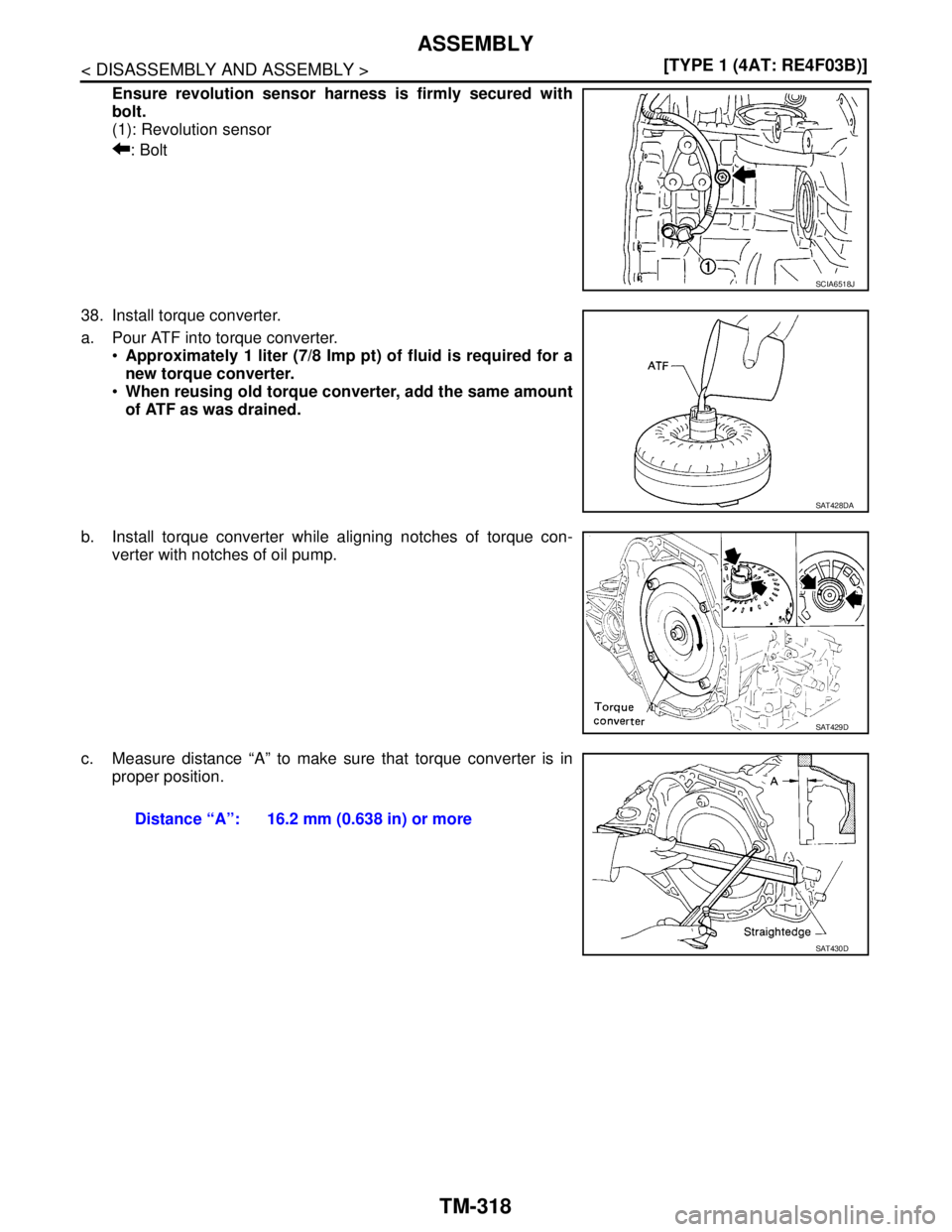
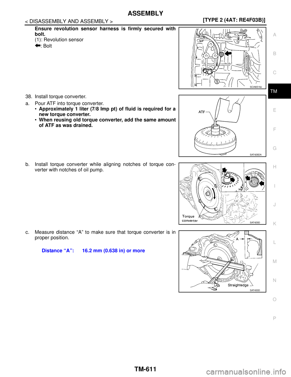
Ensure revolution sensor harness is firmly secured with
bolt.
(1): Revolution sensor
: Bolt
38. Install torque converter.
a. Pour ATF into torque converter.
Approximately 1 liter (7/8 Imp pt) of fluid is required for a
new torque converter.
When reusing old torque converter, add the same amount
of ATF as was drained.
b. Install torque converter while aligning notches of torque con-
verter with notches of oil pump.
c. Measure distance “A” to make sure that torque converter is in
proper position.
SCIA6518J
SAT428DA
SAT429D
Distance “A”: 16.2 mm (0.638 in) or more
SAT430D
Page 5413 of 5883
PRECAUTIONS
TM-467
< PRECAUTION >[TYPE 2 (4AT: RE4F03B)]
C
E
F
G
H
I
J
K
L
MA
B
TM
N
O
P
Before assembly, apply a coat of recommended ATF to all parts. Apply petroleum jelly to protect O-rings and
seals, or hold bearings and washers in place during assembly. Do not use grease.
Extreme care should be taken to avoid damage to O-rings, seals and gaskets when assembling.
After overhaul, refill the A/T with new ATF.
When the A/T drain plug is removed, only some of the fluid is drained. Old A/T fluid will remain in torque con-
verter and ATF cooling system.
Always follow the procedures under “Changing A/T Fluid” in the AT section when changing A/T fluid. Refer to
XX-XX, "*****"
, XX-XX, "*****".
Service Notice or PrecautionINFOID:0000000001723048
TORQUE CONVERTER SERVICE
The torque converter should be replaced under any of the following conditions:
External leaks in the hub weld area.
Converter hub is scored or damaged.
Converter pilot is broken, damaged or fits poorly into crankshaft.
Steel particles are found after flushing the cooler and cooler lines.
Pump is damaged or steel particles are found in the converter.
Vehicle has TCC shudder and/or no TCC apply. Replace only after all hydraulic and electrical diagnoses
have been made. (Converter clutch material may be glazed.)
Converter is contaminated with engine coolant containing antifreeze.
Internal malfunction of stator roller clutch.
Heavy clutch debris due to overheating (blue converter).
Steel particles or clutch lining material found in fluid filter or on magnet when no internal parts in unit are
worn or damaged — indicates that lining material came from converter.
The torque converter should not be replaced if:
The fluid has an odor, is discolored, and there is no evidence of metal or clutch facing particles.
The threads in one or more of the converter bolt holes are damaged.
A/T malfunction did not display evidence of damaged or worn internal parts, steel particles or clutch plate lin-
ing material in unit and inside the fluid filter.
Vehicle has been exposed to high mileage (only). The exception may be where the torque converter clutch
dampener plate lining has seen excess wear by vehicles operated in heavy and/or constant traffic, such as
taxi, delivery or police use.
OBD SELF-DIAGNOSIS (FOR TYPE 1 ONLY)
A/T self-diagnosis is performed by the TCM in combination with the ECM. The results can be read through
the blinking pattern of the OD OFF indicator lamp or the malfunction indicator lamp (MIL). Refer to the table
on XX-XX, "*****"
for the indicator used to display each self-diagnostic result.
The self-diagnostic results indicated by the MIL are automatically stored in both the ECM and TCM memo-
ries.
Always perform the procedure “HOW TO ERASE DTC” on XX-XX, "*****"
to complete the repair and
avoid unnecessary blinking of the MIL.
The following self-diagnostic items can be detected using ECM self-diagnostic results mode* only when the
OD OFF indicator lamp does not indicate any malfunctions.
-PNP switch
- A/T 1st, 2nd, 3rd, or 4th gear function
*: For details of OBD, refer to XX-XX, "*****"
.
Wiring Diagram and Trouble DiagnosisINFOID:0000000001723049
When reading wiring diagrams, refer to the following:
XX-XX, "*****"
XX-XX, "*****"
When performing trouble diagnosis, refer to the following:
XX-XX, "*****"
XX-XX, "*****"
Page 5457 of 5883
OVERHAUL
TM-511
< DISASSEMBLY AND ASSEMBLY >[TYPE 2 (4AT: RE4F03B)]
C
E
F
G
H
I
J
K
L
MA
B
TM
N
O
P
19. Oil pan gasket 20. Oil pan 21. Drain plug gasket
22. Drain plug 23. Magnet 24. Oil pan fitting bolt
25. Snap ring 26. O-ring 27. O-ring
28. N-D accumulator piston29. Return spring 30. O-ring
31. Lip seal 32. Turbine revolution sensor (power
train revolution sensor)33. O-ring
34. Retaining pin 35. Detent spring 36. Retaining pin
37. Manual shaft 38. Manual shaft oil seal 39. Manual plate
40. Parking rod plate 41. Parking rod 42. OD servo piston retainer
43. Snap ring 44. O-ring 45. OD servo piston
46. D-ring 47. Servo piston retainer 48. O-ring
49. E-ring 50. Spring retainer 51. OD servo return spring
52. D-ring 53. Band servo piston 54. Band servo thrust washer
55. Band servo piston stem 56. 2nd servo return spring 57. PNP switch
58. Parking shaft 59. Return spring 60. Output gear adjusting spacer
61. Output gear bearing 62. Output gear 63. Side cover gasket
64. Side cover 65. Side cover fitting bolt 66. Lock nut
67. Idler gear 68. Idler gear bearing 69. Reduction pinion gear adjusting
shim
70. Parking actuator support 71. Parking pawl 72. LH differential side oil seal
73. Revolution sensor
: Apply locking sealant (Loctite #518).
Page 5556 of 5883
TM-610
< DISASSEMBLY AND ASSEMBLY >[TYPE 2 (4AT: RE4F03B)]
ASSEMBLY
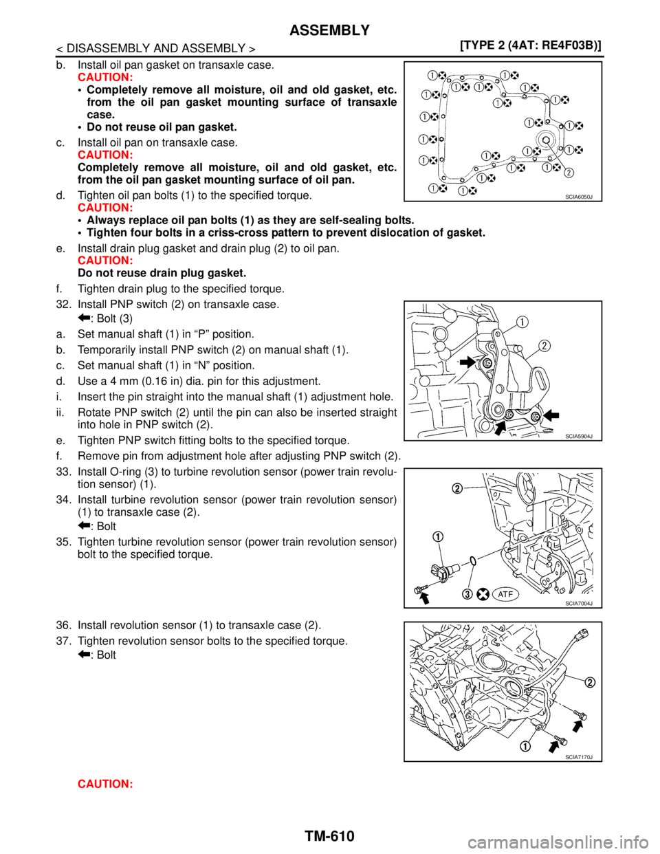
b. Install oil pan gasket on transaxle case.
CAUTION:
Completely remove all moisture, oil and old gasket, etc.
from the oil pan gasket mounting surface of transaxle
case.
Do not reuse oil pan gasket.
c. Install oil pan on transaxle case.
CAUTION:
Completely remove all moisture, oil and old gasket, etc.
from the oil pan gasket mounting surface of oil pan.
d. Tighten oil pan bolts (1) to the specified torque.
CAUTION:
Always replace oil pan bolts (1) as they are self-sealing bolts.
Tighten four bolts in a criss-cross pattern to prevent dislocation of gasket.
e. Install drain plug gasket and drain plug (2) to oil pan.
CAUTION:
Do not reuse drain plug gasket.
f. Tighten drain plug to the specified torque.
32. Install PNP switch (2) on transaxle case.
: Bolt (3)
a. Set manual shaft (1) in “P” position.
b. Temporarily install PNP switch (2) on manual shaft (1).
c. Set manual shaft (1) in “N” position.
d. Use a 4 mm (0.16 in) dia. pin for this adjustment.
i. Insert the pin straight into the manual shaft (1) adjustment hole.
ii. Rotate PNP switch (2) until the pin can also be inserted straight
into hole in PNP switch (2).
e. Tighten PNP switch fitting bolts to the specified torque.
f. Remove pin from adjustment hole after adjusting PNP switch (2).
33. Install O-ring (3) to turbine revolution sensor (power train revolu-
tion sensor) (1).
34. Install turbine revolution sensor (power train revolution sensor)
(1) to transaxle case (2).
: Bolt
35. Tighten turbine revolution sensor (power train revolution sensor)
bolt to the specified torque.
36. Install revolution sensor (1) to transaxle case (2).
37. Tighten revolution sensor bolts to the specified torque.
: Bolt
CAUTION:
SCIA6050J
SCIA5904J
SCIA7004J
SCIA7170J
Page 5557 of 5883
ASSEMBLY
TM-611
< DISASSEMBLY AND ASSEMBLY >[TYPE 2 (4AT: RE4F03B)]
C
E
F
G
H
I
J
K
L
MA
B
TM
N
O
P
Ensure revolution sensor harness is firmly secured with
bolt.
(1): Revolution sensor
: Bolt
38. Install torque converter.
a. Pour ATF into torque converter.
Approximately 1 liter (7/8 Imp pt) of fluid is required for a
new torque converter.
When reusing old torque converter, add the same amount
of ATF as was drained.
b. Install torque converter while aligning notches of torque con-
verter with notches of oil pump.
c. Measure distance “A” to make sure that torque converter is in
proper position.
SCIA6518J
SAT428DA
SAT429D
Distance “A”: 16.2 mm (0.638 in) or more
SAT430D
Page 5570 of 5883
TM-624
< PRECAUTION >[5MT: RS5F91R]
PRECAUTIONS
PRECAUTION
PRECAUTIONS
Service Notice or Precautions for Manual TransaxleINFOID:0000000001381678
CAUTION:
If transaxle assembly is removed from the vehicle, always replace CSC (Concentric Slave Cylinder).
Return CSC insert to original position to remove transaxle assembly. Dust on clutch disc sliding
parts may damage seal of CSC and may cause clutch fluid leakage.
Never reuse transaxle gear oil, once it has been drained.
Check oil level or replace gear oil with vehicle on level surface.
During removal or installation, keep inside of transaxle clear of dust or dirt.
Check for the correct installation status prior to removal or disassembly. If matching marks are
required, be certain they do not interfere with the function of the parts they are applied.
In principle, tighten bolts or nuts gradually in several steps working diagonally from inside to out-
side. If tightening sequence is specified, use it.
Never damage sliding surfaces and mating surfaces.
Page 5580 of 5883
TM-634
< REMOVAL AND INSTALLATION >[5MT: RS5F91R]
TRANSAXLE ASSEMBLY
8. Remove engine undercover.
9. Remove front drive shafts. Refer to FAX-10, "
Removal and Installation (Left Side)" and FAX-11, "Removal
and Installation (Right Side)".
NOTE:
Insert a suitable plug into side oil seal after removing front drive shaft.
10. Remove heat insulator and exhaust front tube. Refer to EX-5, "
Removal and Installation".
11. Disconnect position switch harness connector and then disconnect clip from rear housing.
12. Drain gear oil. Refer to TM-628, "
Draining".
13. Disconnect select cable and shift cable from transaxle assembly. Refer to TM-630, "
Removal and Installa-
tion".
14. Support engine assembly and transaxle assembly with a jack.
CAUTION:
When setting a jack, be careful not to bring it into contact with switch.
15. Remove engine mount through bolt-securing nut. Refer to EM-89, "
Exploded View".
16. Remove LH engine mount bracket (transaxle side) bolts.
17. Remove rear engine mount bracket and rear torque rod.
18. Remove transaxle assembly to engine assembly bolts.
19. Remove transaxle assembly from the vehicle.
CAUTION:
Secure transaxle assembly to a jack while removing it.
INSTALLATION
Installation is in the reverse order of removal.
CAUTION:
When installing transaxle assembly, be careful not to bring transaxle input shaft into contact with
clutch cover.
If transaxle is removed from the vehicle, always replace CSC. Refer to CL-11, "
Removal and Installation".
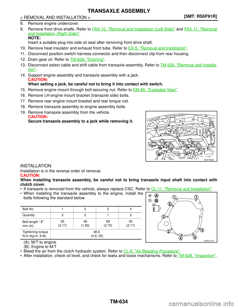
When installing the transaxle assembly to the engine, install the
bolts following the standard below.
(A): M/T to engine
(B): Engine to M/T
Bleed the air from the clutch hydraulic system. Refer to CL-8, "
Air Bleeding Procedure".
After installation, check oil level, and check for leaks and loose mechanisms. Refer to TM-628, "
Inspection".
SCIA7084E
Bolt No. 1234
Quantity 2213
Bolt length “ ”
mm (in)55
(2.17)49
(1.93)69
(2.72)55
(2.17)
Tightening torque
N·m (kg-m, ft-lb)48.0
(4.9, 35)
PCIB1517E
Page 5598 of 5883
TM-652
< DISASSEMBLY AND ASSEMBLY >[5MT: RS5F91R]
TRANSAXLE ASSEMBLY
42. Shift the shift lever (1) of control shaft assembly to neutral posi-
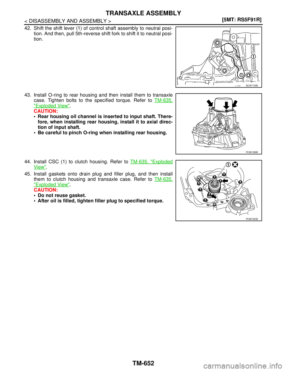
tion. And then, pull 5th-reverse shift fork to shift it to neutral posi-
tion.
43. Install O-ring to rear housing and then install them to transaxle
case. Tighten bolts to the specified torque. Refer to TM-635,
"Exploded View".
CAUTION:
Rear housing oil channel is inserted to input shaft. There-
fore, when installing rear housing, install it to axial direc-
tion of input shaft.
Be careful to pinch O-ring when installing rear housing.
44. Install CSC (1) to clutch housing. Refer to TM-635, "
Exploded
View".
45. Install gaskets onto drain plug and filler plug, and then install
them to clutch housing and transaxle case. Refer to TM-635,
"Exploded View".
CAUTION:
Do not reuse gasket.
After oil is filled, tighten filler plug to specified torque.
SCIA7130E
PCIB1558E
PCIB1523E