Page 3281 of 5883
GW-22
< ON-VEHICLE REPAIR >
REAR DOOR GLASS AND REGULATOR
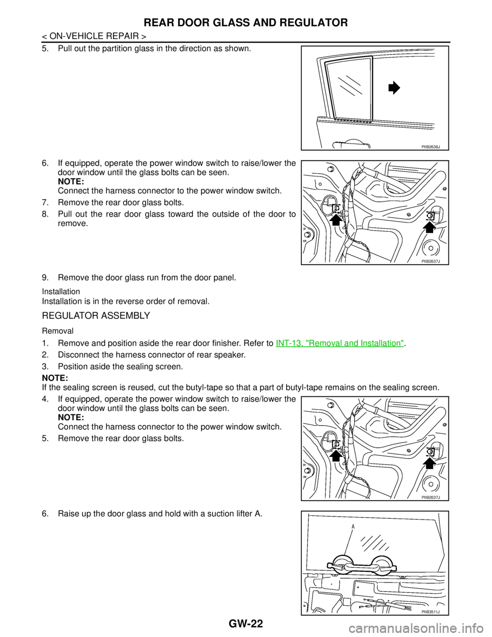
5. Pull out the partition glass in the direction as shown.
6. If equipped, operate the power window switch to raise/lower the
door window until the glass bolts can be seen.
NOTE:
Connect the harness connector to the power window switch.
7. Remove the rear door glass bolts.
8. Pull out the rear door glass toward the outside of the door to
remove.
9. Remove the door glass run from the door panel.
Installation
Installation is in the reverse order of removal.
REGULATOR ASSEMBLY
Removal
1. Remove and position aside the rear door finisher. Refer to INT-13, "Removal and Installation".
2. Disconnect the harness connector of rear speaker.
3. Position aside the sealing screen.
NOTE:
If the sealing screen is reused, cut the butyl-tape so that a part of butyl-tape remains on the sealing screen.
4. If equipped, operate the power window switch to raise/lower the
door window until the glass bolts can be seen.
NOTE:
Connect the harness connector to the power window switch.
5. Remove the rear door glass bolts.
6. Raise up the door glass and hold with a suction lifter A.
PIIB2636J
PIIB2637J
PIIB2637J
PIIB3511J
Page 3282 of 5883
REAR DOOR GLASS AND REGULATOR
GW-23
< ON-VEHICLE REPAIR >
C
D
E
F
G
H
I
J
L
MA
B
GW
N
O
P
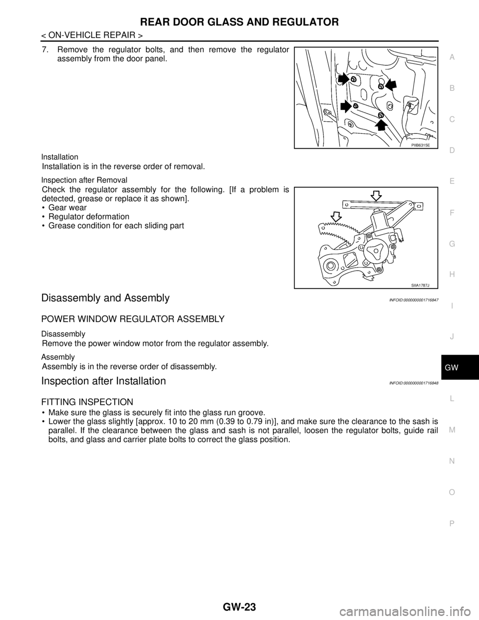
7. Remove the regulator bolts, and then remove the regulator
assembly from the door panel.
Installation
Installation is in the reverse order of removal.
Inspection after Removal
Check the regulator assembly for the following. [If a problem is
detected, grease or replace it as shown].
Gear wear
Regulator deformation
Grease condition for each sliding part
Disassembly and AssemblyINFOID:0000000001716847
POWER WINDOW REGULATOR ASSEMBLY
Disassembly
Remove the power window motor from the regulator assembly.
Assembly
Assembly is in the reverse order of disassembly.
Inspection after InstallationINFOID:0000000001716848
FITTING INSPECTION
Make sure the glass is securely fit into the glass run groove.
Lower the glass slightly [approx. 10 to 20 mm (0.39 to 0.79 in)], and make sure the clearance to the sash is
parallel. If the clearance between the glass and sash is not parallel, loosen the regulator bolts, guide rail
bolts, and glass and carrier plate bolts to correct the glass position.
PIIB6315E
SIIA1787J
Page 3315 of 5883
COMPRESSOR
HA-33
< ON-VEHICLE REPAIR >
C
D
E
F
G
H
J
K
L
MA
B
HA
N
O
P
6. Remove bolts (A) from compressor (1), using power tools.
7. Remove compressor (1) downward from the engine compart-
ment.
INSPECTION FOR CLUTCH DISC TO PULLEY CLEARANCE
1. Check the clearance around the entire periphery of the clutch disc.
Measure the clearance for the compressor as shown.
2. If specified clearance is not obtained, replace compressor.
INSTALLATION
Installation is in the reverse order of removal.
CAUTION:
Replace O-rings of low-pressure flexible hose and high-pressure flexible hose with a new ones, and
apply compressor oil when installing.
When recharging refrigerant, check for leaks. Refer to HA-22, "
Checking of Refrigerant Leaks".
SJIA0672E
Clutch disc to pulley clearance : 0.3 - 0.6 mm (0.012 - 0.024 in)
RHA087E
Page 3317 of 5883
COMPRESSOR
HA-35
< ON-VEHICLE REPAIR >
C
D
E
F
G
H
J
K
L
MA
B
HA
N
O
P
1. Check the clearance around the entire periphery of the clutch disc.
Measure the clearance for the compressor as shown.
2. If specified clearance is not obtained, replace compressor.
INSTALLATION
Installation is in the reverse order of removal.
CAUTION:
Replace O-rings of low-pressure flexible hose and high-pressure flexible hose with new ones, and
apply compressor oil when installing.
When recharging refrigerant, check for leaks. Refer to HA-22, "
Checking of Refrigerant Leaks".
Removal and Installation of Compressor - K9KINFOID:0000000001523297
K9K
REMOVAL
1. Use the recovery/recycling equipment to evacuate the refrigerant. Refer to HA-29, "HFC-134a (R-134a)
Service Procedure".
2. Remove the engine cover.
3. Remove the front grille. Refer to EXT-19, "
Removal and Installation". Clutch disc to pulley clearance : 0.3 - 0.6 mm (0.012 - 0.024 in)
RHA087E
ALIIA0094GB
Page 3318 of 5883
HA-36
< ON-VEHICLE REPAIR >
COMPRESSOR
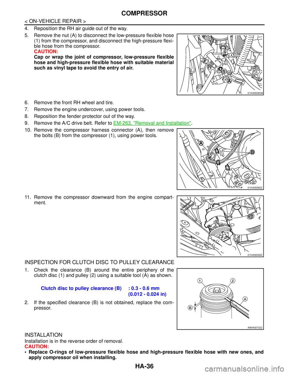
4. Reposition the RH air guide out of the way.
5. Remove the nut (A) to disconnect the low-pressure flexible hose
(1) from the compressor, and disconnect the high-pressure flexi-
ble hose from the compressor.
CAUTION:
Cap or wrap the joint of compressor, low-pressure flexible
hose and high-pressure flexible hose with suitable material
such as vinyl tape to avoid the entry of air.
6. Remove the front RH wheel and tire.
7. Remove the engine undercover, using power tools.
8. Reposition the fender protector out of the way.
9. Remove the A/C drive belt. Refer to EM-263, "
Removal and Installation".
10. Remove the compressor harness connector (A), then remove
the bolts (B) from the compressor (1), using power tools.
11. Remove the compressor downward from the engine compart-
ment.
INSPECTION FOR CLUTCH DISC TO PULLEY CLEARANCE
1. Check the clearance (B) around the entire periphery of the
clutch disc (1) and pulley (2) using a suitable tool (A) as shown.
2. If the specified clearance (B) is not obtained, replace the com-
pressor.
INSTALLATION
Installation is in the reverse order of removal.
CAUTION:
Replace O-rings of low-pressure flexible hose and high-pressure flexible hose with new ones, and
apply compressor oil when installing.
E1KIA0036GB
E1KIA0038ZZ
E1KIA0039ZZ
Clutch disc to pulley clearance (B) : 0.3 - 0.6 mm
(0.012 - 0.024 in)
AWIIA0273ZZ
Page 3320 of 5883
HA-38
< ON-VEHICLE REPAIR >
LOW-PRESSURE FLEXIBLE HOSE
LOW-PRESSURE FLEXIBLE HOSE
Removal and Installation of Low-Pressure Flexible Hose - MR18DE, HR16DE
INFOID:0000000001404150
REMOVAL
1. Use the recovery/recycling equipment to evacuate the refrigerant. Refer to HA-21, "HFC-134a (R-134a)
Service Procedure".
2. Remove engine cover.
3. Remove cowl top cover. Refer to EXT-20, "
Removal and Installation".
4. Remove lower dash insulator.
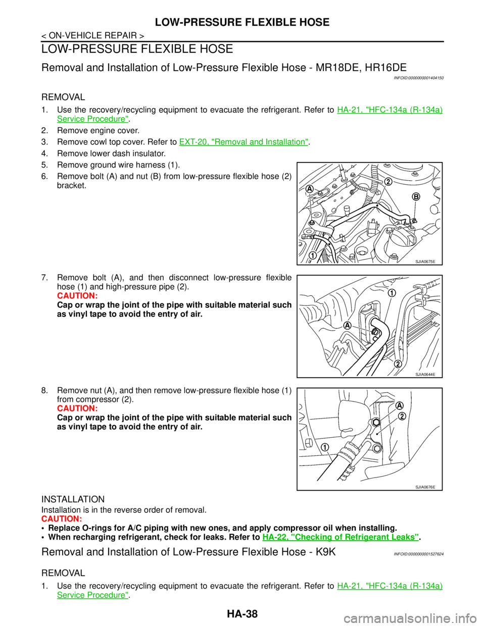
5. Remove ground wire harness (1).
6. Remove bolt (A) and nut (B) from low-pressure flexible hose (2)
bracket.
7. Remove bolt (A), and then disconnect low-pressure flexible
hose (1) and high-pressure pipe (2).
CAUTION:
Cap or wrap the joint of the pipe with suitable material such
as vinyl tape to avoid the entry of air.
8. Remove nut (A), and then remove low-pressure flexible hose (1)
from compressor (2).
CAUTION:
Cap or wrap the joint of the pipe with suitable material such
as vinyl tape to avoid the entry of air.
INSTALLATION
Installation is in the reverse order of removal.
CAUTION:
Replace O-rings for A/C piping with new ones, and apply compressor oil when installing.
When recharging refrigerant, check for leaks. Refer to HA-22, "
Checking of Refrigerant Leaks".
Removal and Installation of Low-Pressure Flexible Hose - K9KINFOID:0000000001527624
REMOVAL
1. Use the recovery/recycling equipment to evacuate the refrigerant. Refer to HA-21, "HFC-134a (R-134a)
Service Procedure".
SJIA0675E
SJIA0644E
SJIA0676E
Page 3321 of 5883

LOW-PRESSURE FLEXIBLE HOSE
HA-39
< ON-VEHICLE REPAIR >
C
D
E
F
G
H
J
K
L
MA
B
HA
N
O
P
2. Remove the engine cover.
3. Remove the front grille. Refer to EXT-19, "
Removal and Installation".
4. Reposition the RH air guide out of the way.
5. Remove the nut (A) to disconnect the low-pressure flexible hose
(1) from the compressor.
CAUTION:
Cap or wrap the joint of compressor, low-pressure flexible
hose and high-pressure flexible hose with suitable material
such as vinyl tape to avoid the entry of air.
6. Disconnect the low-pressure pipe from the low-pressure flexible hose.
CAUTION:
Cap or wrap the joint of the pipe with suitable material such as vinyl tape to avoid the entry of air.
7. Remove the low-pressure flexible hose.
INSTALLATION
Installation is in the reverse order of removal.
CAUTION:
Replace O-rings for A/C piping with new ones, and apply compressor oil when installing.
When recharging refrigerant, check for leaks. Refer to HA-22, "
Checking of Refrigerant Leaks".
E1KIA0036GB
Page 3322 of 5883
HA-40
< ON-VEHICLE REPAIR >
LOW-PRESSURE PIPE
LOW-PRESSURE PIPE
Removal and Installation of Low-Pressure Pipe - K9KINFOID:0000000001404236
REMOVAL
1. Use the recovery/recycling equipment to evacuate the refrigerant. Refer to HA-21, "HFC-134a (R-134a)
Service Procedure".
2. Remove engine cover.
3. Remove cowl top cover. Refer to EXT-20, "
Removal and Installation".
4. Reposition the lower dash insulator out of the way.
5. Remove the front grille. Refer to EXT-19, "
Removal and Installation".
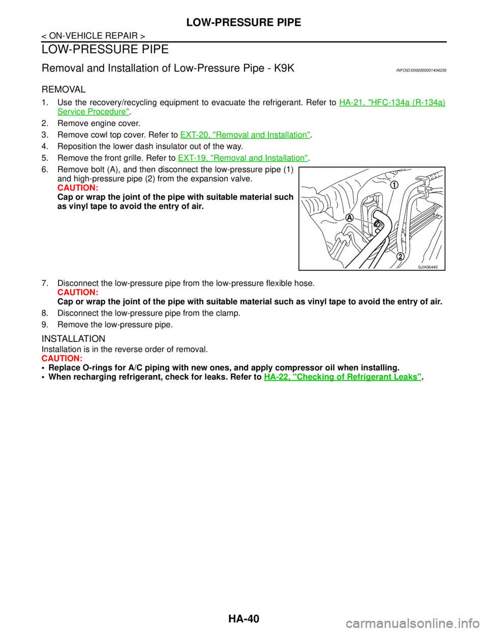
6. Remove bolt (A), and then disconnect the low-pressure pipe (1)
and high-pressure pipe (2) from the expansion valve.
CAUTION:
Cap or wrap the joint of the pipe with suitable material such
as vinyl tape to avoid the entry of air.
7. Disconnect the low-pressure pipe from the low-pressure flexible hose.
CAUTION:
Cap or wrap the joint of the pipe with suitable material such as vinyl tape to avoid the entry of air.
8. Disconnect the low-pressure pipe from the clamp.
9. Remove the low-pressure pipe.
INSTALLATION
Installation is in the reverse order of removal.
CAUTION:
Replace O-rings for A/C piping with new ones, and apply compressor oil when installing.
When recharging refrigerant, check for leaks. Refer to HA-22, "
Checking of Refrigerant Leaks".
SJIA0644E