Page 3325 of 5883

HIGH-PRESSURE PIPE
HA-43
< ON-VEHICLE REPAIR >
C
D
E
F
G
H
J
K
L
MA
B
HA
N
O
P
HIGH-PRESSURE PIPE
Removal and Installation of High-Pressure Pipe - MR18DE, HR16DEINFOID:0000000001404219
REMOVAL
1. Remove low-pressure flexible hose. Refer to HA-38, "Removal and Installation of Low-Pressure Flexible
Hose - MR18DE, HR16DE".
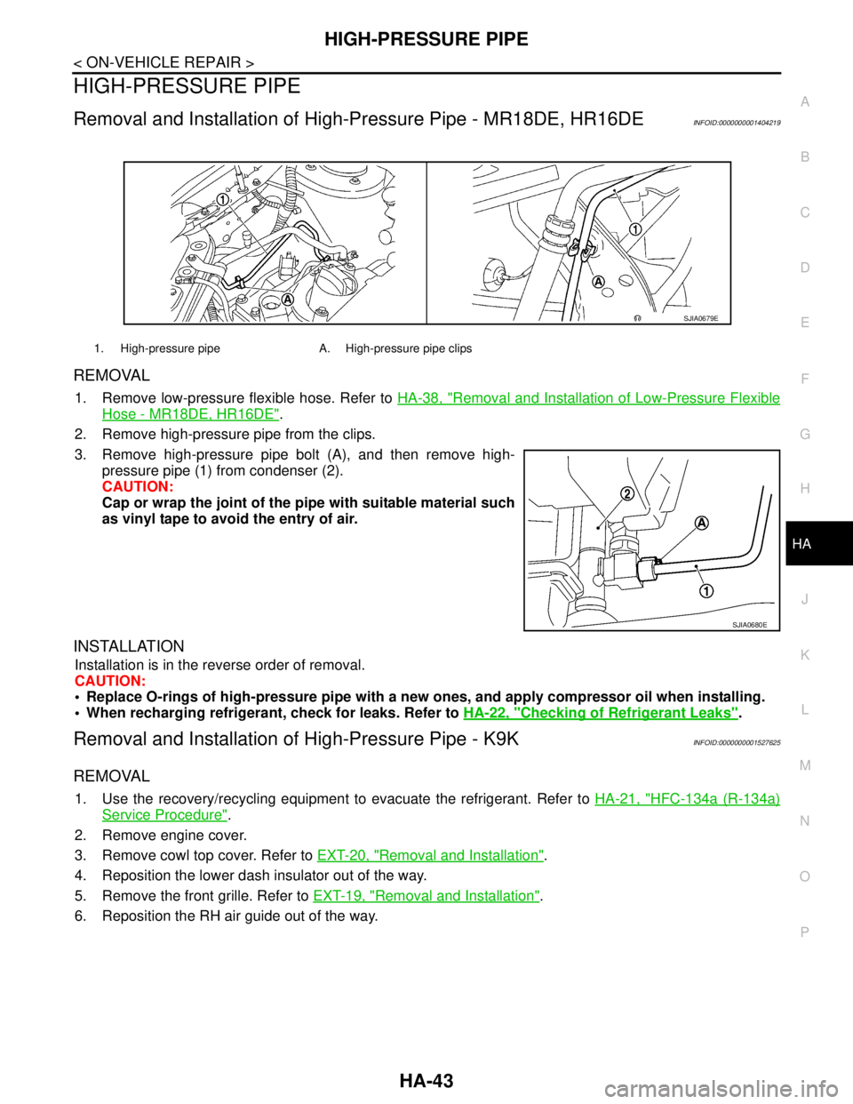
2. Remove high-pressure pipe from the clips.
3. Remove high-pressure pipe bolt (A), and then remove high-
pressure pipe (1) from condenser (2).
CAUTION:
Cap or wrap the joint of the pipe with suitable material such
as vinyl tape to avoid the entry of air.
INSTALLATION
Installation is in the reverse order of removal.
CAUTION:
Replace O-rings of high-pressure pipe with a new ones, and apply compressor oil when installing.
When recharging refrigerant, check for leaks. Refer to HA-22, "
Checking of Refrigerant Leaks".
Removal and Installation of High-Pressure Pipe - K9KINFOID:0000000001527625
REMOVAL
1. Use the recovery/recycling equipment to evacuate the refrigerant. Refer to HA-21, "HFC-134a (R-134a)
Service Procedure".
2. Remove engine cover.
3. Remove cowl top cover. Refer to EXT-20, "
Removal and Installation".
4. Reposition the lower dash insulator out of the way.
5. Remove the front grille. Refer to EXT-19, "
Removal and Installation".
6. Reposition the RH air guide out of the way.
1. High-pressure pipe A. High-pressure pipe clips
SJIA0679E
SJIA0680E
Page 3331 of 5883

EXPANSION VALVE
HA-49
< ON-VEHICLE REPAIR >
C
D
E
F
G
H
J
K
L
MA
B
HA
N
O
P
EXPANSION VALVE
Removal and Installation of Expansion Valve - MR18DE, HR16DE and K9K
INFOID:0000000001527645
REMOVAL
1. Use the recovery/recycling equipment to evacuate the refrigerant. Refer to HA-21, "HFC-134a (R-134a)
Service Procedure".
2. Remove cowl top cover. Refer to EXT-20, "
Removal and Installation".
3. Remove lower dash insulator.
4. Disconnect low-pressure flexible hose and high-pressure pipe from evaporator. Refer to HA-27, "
Compo-
nent".
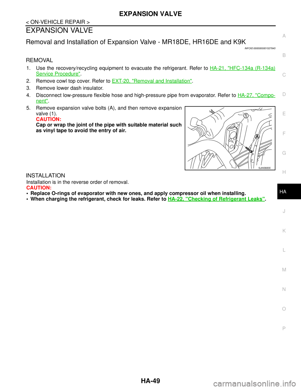
5. Remove expansion valve bolts (A), and then remove expansion
valve (1).
CAUTION:
Cap or wrap the joint of the pipe with suitable material such
as vinyl tape to avoid the entry of air.
INSTALLATION
Installation is in the reverse order of removal.
CAUTION:
Replace O-rings of evaporator with new ones, and apply compressor oil when installing.
When charging the refrigerant, check for leaks. Refer to HA-22, "
Checking of Refrigerant Leaks".
SJIA0683E
Page 4867 of 5883

ST-12
< ON-VEHICLE REPAIR >
STEERING GEAR
STEERING GEAR
Removal and InstallationINFOID:0000000001282501
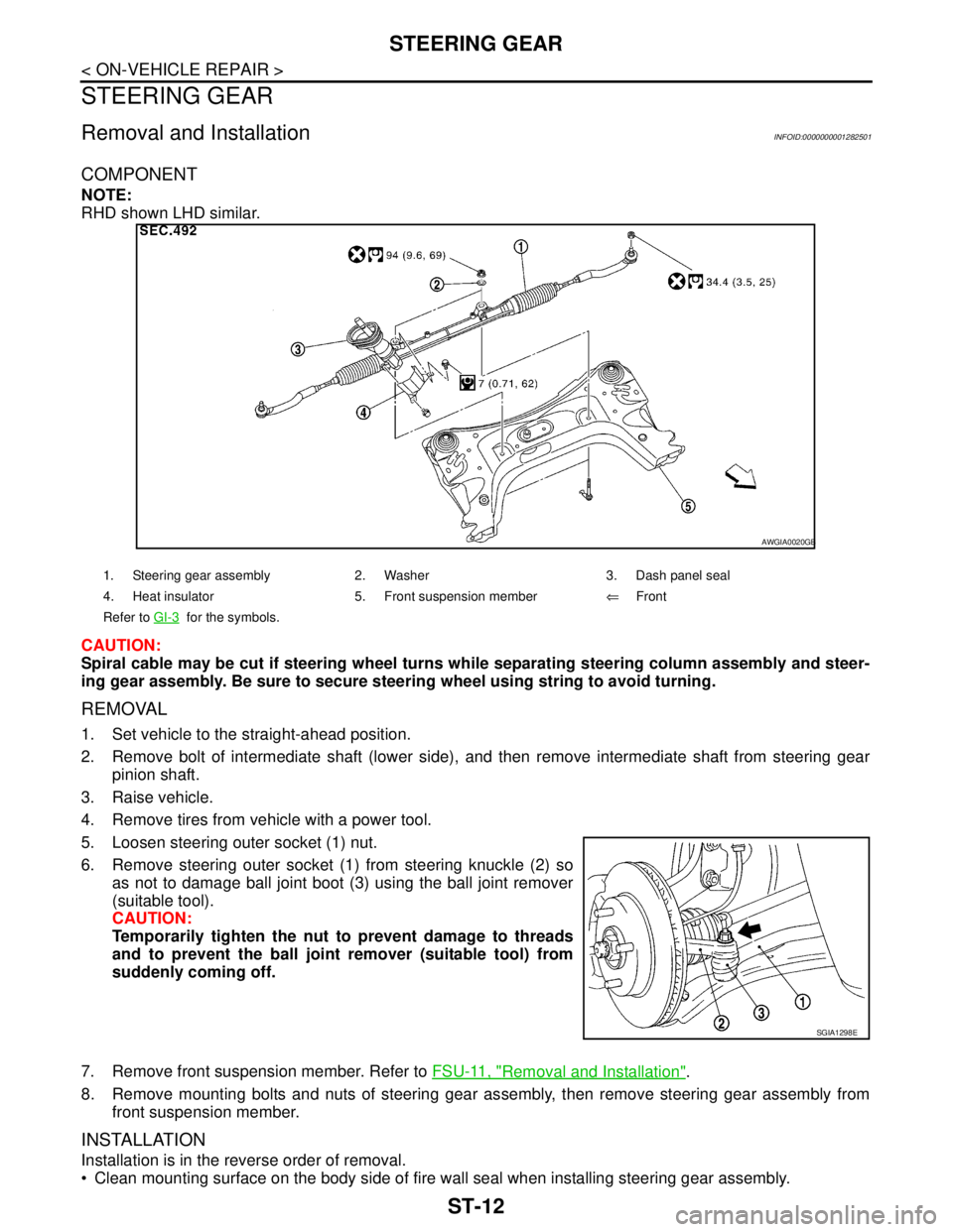
COMPONENT
NOTE:
RHD shown LHD similar.
CAUTION:
Spiral cable may be cut if steering wheel turns while separating steering column assembly and steer-
ing gear assembly. Be sure to secure steering wheel using string to avoid turning.
REMOVAL
1. Set vehicle to the straight-ahead position.
2. Remove bolt of intermediate shaft (lower side), and then remove intermediate shaft from steering gear
pinion shaft.
3. Raise vehicle.
4. Remove tires from vehicle with a power tool.
5. Loosen steering outer socket (1) nut.
6. Remove steering outer socket (1) from steering knuckle (2) so
as not to damage ball joint boot (3) using the ball joint remover
(suitable tool).
CAUTION:
Temporarily tighten the nut to prevent damage to threads
and to prevent the ball joint remover (suitable tool) from
suddenly coming off.
7. Remove front suspension member. Refer to FSU-11, "
Removal and Installation".
8. Remove mounting bolts and nuts of steering gear assembly, then remove steering gear assembly from
front suspension member.
INSTALLATION
Installation is in the reverse order of removal.
Clean mounting surface on the body side of fire wall seal when installing steering gear assembly.
1. Steering gear assembly 2. Washer 3. Dash panel seal
4. Heat insulator 5. Front suspension member⇐Front
Refer to GI-3
for the symbols.
AWGIA0020GB
SGIA1298E
Page 4869 of 5883

ST-14
< DISASSEMBLY AND ASSEMBLY >
STEERING GEAR
DISASSEMBLY AND ASSEMBLY
STEERING GEAR
Disassembly and AssemblyINFOID:0000000001282504
COMPONENT (R24K TYPE)
NOTE:
RHD shown LHD similar.
CAUTION:
Clean steering gear assembly with kerosene before disassembling.
DISASSEMBLY
1. Loosen outer socket lock nut, and then remove outer socket from inner socket.
2. Remove boot clamps, and then remove boot from inner socket.
CAUTION:
Do not damage inner socket and gear housing assembly when removing boot. Inner socket and
gear housing assembly must be replaced if inner socket and gear housing assembly are damaged
because it may allow foreign material to enter.
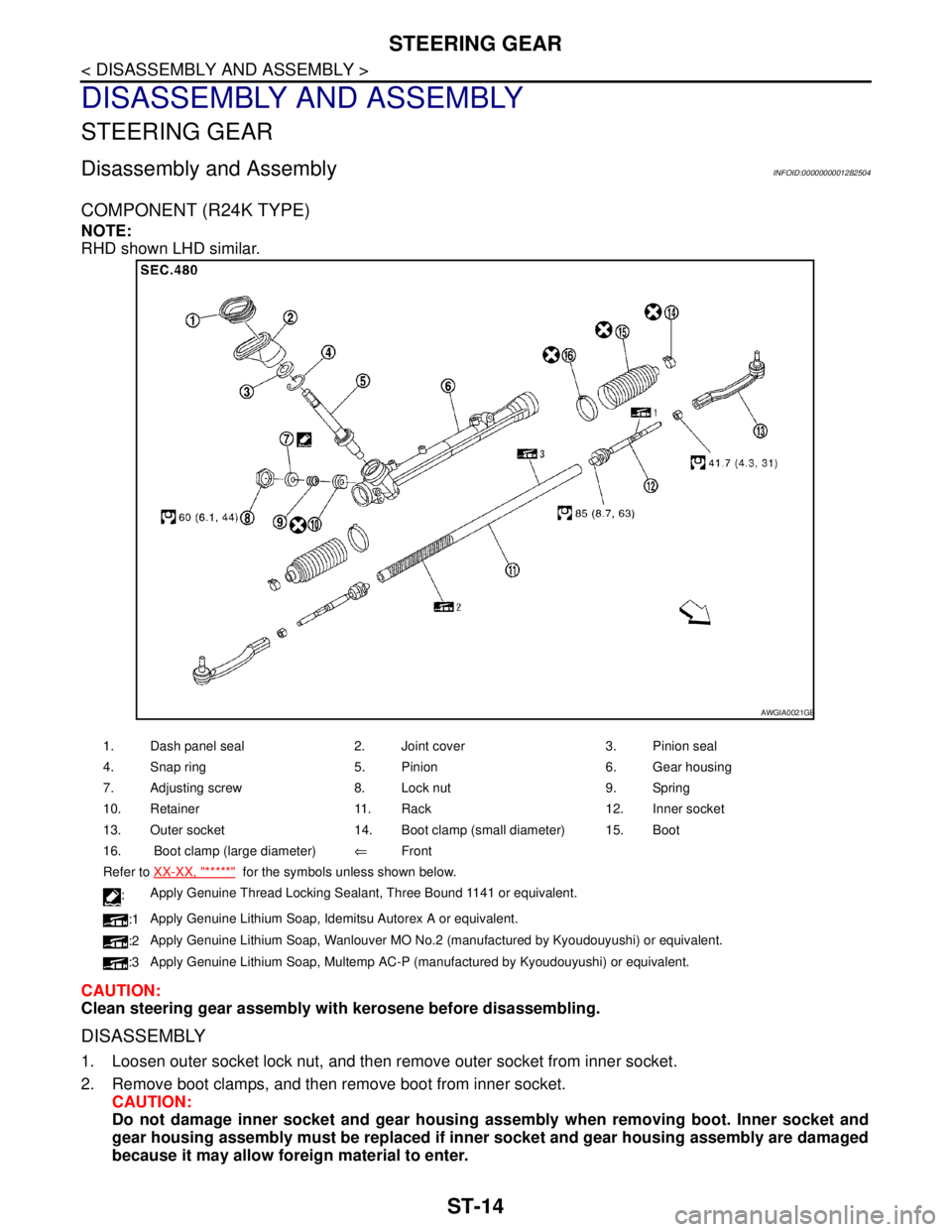
1. Dash panel seal 2. Joint cover 3. Pinion seal
4. Snap ring 5. Pinion 6. Gear housing
7. Adjusting screw 8. Lock nut 9. Spring
10. Retainer 11. Rack 12. Inner socket
13. Outer socket 14. Boot clamp (small diameter) 15. Boot
16. Boot clamp (large diameter)⇐Front
Refer to XX-XX, "*****"
for the symbols unless shown below.
:Apply Genuine Thread Locking Sealant, Three Bound 1141 or equivalent.
:1Apply Genuine Lithium Soap, Idemitsu Autorex A or equivalent.
:2Apply Genuine Lithium Soap, Wanlouver MO No.2 (manufactured by Kyoudouyushi) or equivalent.
:3Apply Genuine Lithium Soap, Multemp AC-P (manufactured by Kyoudouyushi) or equivalent.
AWGIA0021GB
Page 5673 of 5883
![NISSAN TIIDA 2007 Service Repair Manual VTL-12
< ON-VEHICLE REPAIR >[AUTOMATIC AIR CONDITIONER]
A/C UNIT ASSEMBLY
A/C UNIT ASSEMBLY
Removal and InstallationINFOID:0000000001696285
NOTE:
A LHD model shown, RHD model similar.
REMOVAL
1. Use t NISSAN TIIDA 2007 Service Repair Manual VTL-12
< ON-VEHICLE REPAIR >[AUTOMATIC AIR CONDITIONER]
A/C UNIT ASSEMBLY
A/C UNIT ASSEMBLY
Removal and InstallationINFOID:0000000001696285
NOTE:
A LHD model shown, RHD model similar.
REMOVAL
1. Use t](/manual-img/5/57395/w960_57395-5672.png)
VTL-12
< ON-VEHICLE REPAIR >[AUTOMATIC AIR CONDITIONER]
A/C UNIT ASSEMBLY
A/C UNIT ASSEMBLY
Removal and InstallationINFOID:0000000001696285
NOTE:
A LHD model shown, RHD model similar.
REMOVAL
1. Use the recovery/recycling equipment (for HFC-134a) to discharge the refrigerant. Refer to HA-29, "HFC-
134a (R-134a) Service Procedure".
2. Drain the coolant from the cooling system. Refer to CO-11, "
Changing Engine Coolant" (HR16DE), CO-
35, "Changing Engine Coolant" (MR18DE), CO-58, "Draining" (K9K).
3. Remove cowl top cover. Refer to EXT-20, "
Removal and Installation".
4. Remove lower dash insulator.
5. Remove bolt (A), and then disconnect low-pressure flexible
hose (1) and high-pressure pipe (2) from evaporator.
CAUTION:
Cap or wrap the joint of the pipe with suitable material such
as vinyl tape to avoid the entry of air.
6. Remove clamps (A), and then disconnect heater hoses (1) from
heater core.
SJIA0648E
A. A/C unit assembly bolts B. Steering member bolts C. Steering column nuts
SJIA0644E
SJIA0645E
Page 5698 of 5883
![NISSAN TIIDA 2007 Service Repair Manual A/C UNIT ASSEMBLY
VTL-37
< ON-VEHICLE REPAIR >[MANUAL AIR CONDITIONER]
C
D
E
F
G
H
J
K
L
MA
B
VTL
N
O
P
A/C UNIT ASSEMBLY
Removal and InstallationINFOID:0000000001696531
NOTE:
A LHD model shown, RHD m NISSAN TIIDA 2007 Service Repair Manual A/C UNIT ASSEMBLY
VTL-37
< ON-VEHICLE REPAIR >[MANUAL AIR CONDITIONER]
C
D
E
F
G
H
J
K
L
MA
B
VTL
N
O
P
A/C UNIT ASSEMBLY
Removal and InstallationINFOID:0000000001696531
NOTE:
A LHD model shown, RHD m](/manual-img/5/57395/w960_57395-5697.png)
A/C UNIT ASSEMBLY
VTL-37
< ON-VEHICLE REPAIR >[MANUAL AIR CONDITIONER]
C
D
E
F
G
H
J
K
L
MA
B
VTL
N
O
P
A/C UNIT ASSEMBLY
Removal and InstallationINFOID:0000000001696531
NOTE:
A LHD model shown, RHD model similar.
REMOVAL
1. Use a recovery/recycling equipment (for HFC-134a) to discharge refrigerant. Refer to HA-29, "HFC-134a
(R-134a) Service Procedure".
2. Drain coolant from cooling system. Refer to CO-11, "
Changing Engine Coolant" (HR16DE), CO-35,
"Changing Engine Coolant" (MR18DE), CO-58, "Draining" (K9K).
3. Remove cowl top cover. Refer to EXT-20, "
Removal and Installation".
4. Remove lower dash insulator.
5. Remove bolt (A), and then disconnect low-pressure flexible
hose (1) and high-pressure pipe (2) from evaporator.
CAUTION:
Cap or wrap the joint of the pipe with suitable material such
as vinyl tape to avoid the entry of air.
6. Remove clamps (A), and then disconnect heater hoses (1) from
heater core.
A. A/C unit assembly bolts B. Steering member bolts C. Steering column nuts
SJIA0648E
SJIA0644E
SJIA0645E
Page:
< prev 1-8 9-16 17-24