2007 NISSAN TIIDA Brake System BR
[x] Cancel search: Brake System BRPage 4295 of 5883

CHASSIS AND BODY MAINTENANCE
MA-55
< ON-VEHICLE MAINTENANCE >
C
D
E
F
G
H
I
J
K
L
MB
MAN
OA
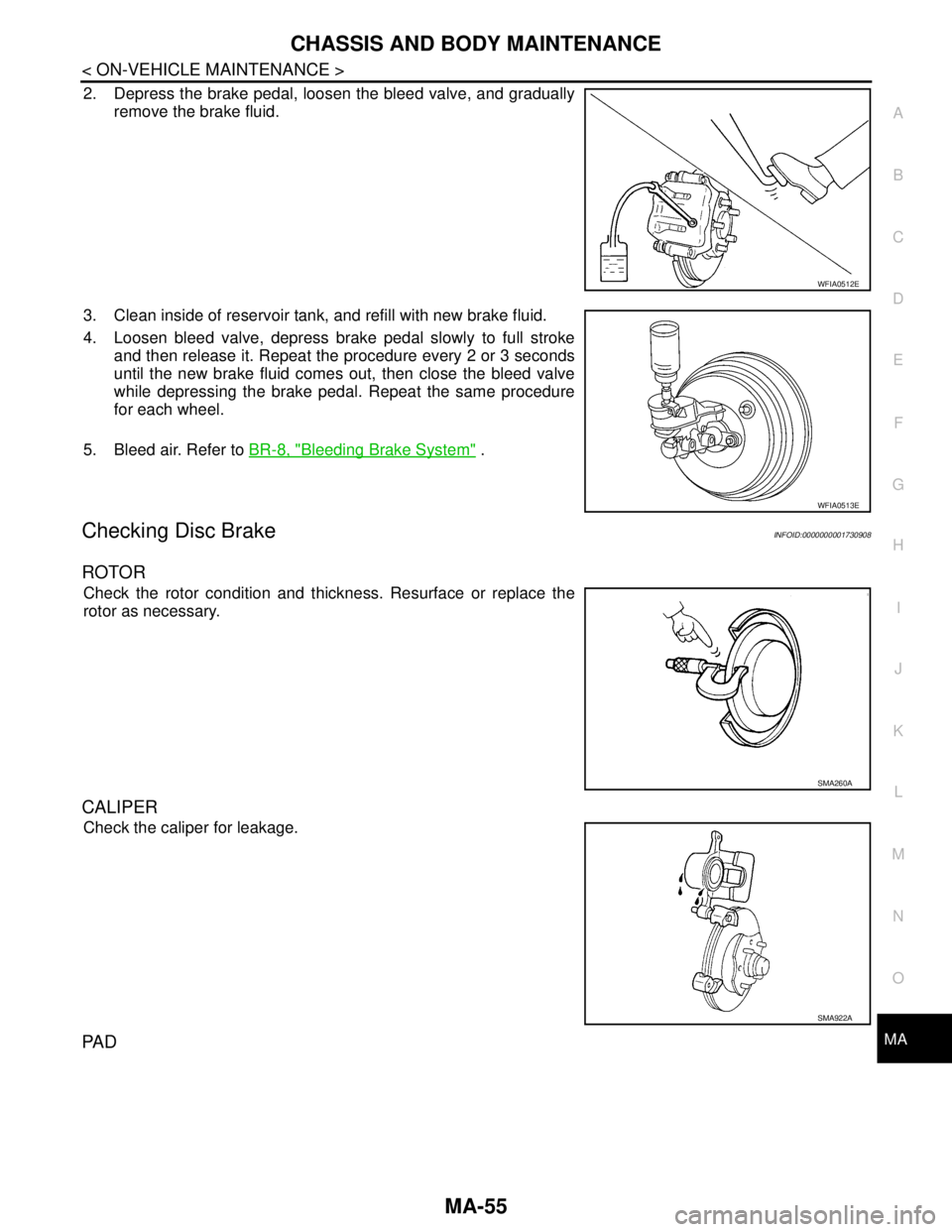
2. Depress the brake pedal, loosen the bleed valve, and gradually
remove the brake fluid.
3. Clean inside of reservoir tank, and refill with new brake fluid.
4. Loosen bleed valve, depress brake pedal slowly to full stroke
and then release it. Repeat the procedure every 2 or 3 seconds
until the new brake fluid comes out, then close the bleed valve
while depressing the brake pedal. Repeat the same procedure
for each wheel.
5. Bleed air. Refer to BR-8, "
Bleeding Brake System" .
Checking Disc BrakeINFOID:0000000001730908
ROTOR
Check the rotor condition and thickness. Resurface or replace the
rotor as necessary.
CALIPER
Check the caliper for leakage.
PA D
WFIA0512E
WFIA0513E
SMA260A
SMA922A
Page 4330 of 5883

MWI
DIAGNOSIS SYSTEM (METER)
MWI-23
< FUNCTION DIAGNOSIS >
C
D
E
F
G
H
I
J
K
L
MB A
O
P
NOTE:
Some items are not available due to vehicle specification.
*: The monitor will indicate “OFF” even though the brake warning lamp is on if either of the following conditions exist.
The parking brake is engaged
The brake fluid level is lowDOOR W/L [ON/OFF] X Displays [ON/OFF] condition of door warning lamp.
HI-BEAM IND [ON/OFF] X Displays [ON/OFF] condition of high beam indicator.
TURN IND [ON/OFF] X Displays [ON/OFF] condition of turn indicator.
FR FOG IND X Displays [ON/OFF] condition of front fog lamp indicator.
RR FOG IND X Displays [ON/OFF] condition of rear fog lamp indicator.
OIL W/L [ON/OFF] X Displays [ON/OFF] condition of oil pressure warning lamp.
LIGHT IND X Displays [ON/OFF] condition of exterior lamp indicator.
VDC/TCS IND [ON/OFF] X Displays [ON/OFF] condition of VDC OFF indicator lamp.
ABS W/L [ON/OFF] X Displays [ON/OFF] condition of ABS warning lamp.
SLIP IND [ON/OFF] X Displays [ON/OFF] condition of SLIP indicator lamp.
BRAKE W/L [ON/OFF] X Displays [ON/OFF] condition of brake warning lamp.*
OIL LEVEL IND X Displays [ON/OFF] condition of oil level indicator.
KEY G W/L [ON/OFF] X Displays [ON/OFF] condition of key green warning lamp.
KEY R W/L [ON/OFF] X Displays [ON/OFF] condition of key red warning lamp.
KEY KNOB W/L [ON/OFF] X Displays [ON/OFF] condition of key knob warning lamp.
PNP P SW X X Displays [ON/OFF] condition of inhibitor P switch.
PNP N SW X X Displays [ON/OFF] condition of inhibitor N switch.
O/D OFF SW X Displays [ON/OFF] condition of O/D OFF switch.
BRAKE SW [ON/OFF] X Displays [ON/OFF] condition of parking brake switch.
P RANGE IND [ON/OFF] X X Displays [ON/OFF] condition of A/T shift P range indicator.
R RANGE IND [ON/OFF] X X Displays [ON/OFF] condition of A/T shift R range indicator.
N RANGE IND [ON/OFF] X X Displays [ON/OFF] condition of A/T shift N range indicator.
D RANGE IND [ON/OFF] X X Displays [ON/OFF] condition of A/T shift D range indicator.
2 RANGE IND [ON/OFF] X X Displays [ON/OFF] condition of A/T shift 2 range indicator.
1 RANGE IND [ON/OFF] X X Displays [ON/OFF] condition of A/T shift 1range indicator.
O/D OFF W/L X Displays [ON/OFF] condition of O/D OFF indicator lamp.
CRUISE IND [ON/OFF] X Displays [ON/OFF] condition of CRUISE indicator.
EPS W/L X Displays [ON/OFF] condition of EPS warning lamp. Display item [Unit]MAIN
SIGNALSSELECTION
FROM MENUDescription
Page 4361 of 5883

MWI-54
< ECU DIAGNOSIS >
COMBINATION METER
DTC Index
INFOID:0000000001374709
NOTE:
“TIME” indicates the following.
0: Indicates that a malfunction is detected at present.
1-63: Indicates that a malfunction was detected in the past. (Displays number of ignition switch OFF → ON
cycles after malfunction is detected. Self-diagnosis result is erased when “63” is exceeded.)
Function Specifications
Speedometer
Zero indication. Tachometer
Fuel gauge
Illumination control Meter illumination Change to nighttime mode when communication is lost.
Segment LCD Odometer Freeze current indication.
Buzzer Buzzer turns off.
Warning lamp/indicator lampABS warning lamp
Lamp turns on when communication is lost. Brake warning lamp
ESP OFF indicator lamp
SLIP indicator lamp
Side and headlight indicator
Lamp turns off when communication is lost. Low water temperature indicator lamp
High water temperature warning lamp
Malfunction indicator
Power steering warning lamp
Air bag warning lamp
High beam indicator
Turn signal indicator lamp
Intelligent Key system warning lamp
CRUISE indicator lamp
Oil pressure warning lamp
Door warning lamp
Front fog lamp indicator
Rear fog lamp indicator
O/D OFF indicator lamp
Lamp turns off when disconnected. Charge warning lamp
Driver and passenger seat belt warn-
ing lamp
CONSULT-III display MalfunctionReference
page
CAN COMM CIRC
[U1000]Malfunction is detected in CAN communication.
CAUTION:
Even when there is no malfunction on CAN communication system, malfunction may be
misinterpreted when battery has low voltage (when maintaining 7 - 8 V for about 2 sec-
onds) or 10A fuse [No. 19, located in the fuse block (J/B)] is disconnected.MWI-24
VEHICLE SPEED
CIRC
[B2205]Malfunction is detected when an erroneous speed signal is input.
CAUTION:
Even when there is no malfunction on speed signal system, malfunction may be misin-
terpreted when battery has low voltage (when maintaining 7 - 8 V for about 2 seconds). MWI-25
Page 4405 of 5883

PB-1
BRAKES
C
D
E
G
H
I
J
K
L
M
SECTION PB
A
B
PB
N
O
P
CONTENTS
PARKING BRAKE SYSTEM
PRECAUTION ...............................................2
PRECAUTIONS ...................................................2
Precaution for Supplemental Restraint System
(SRS) "AIR BAG" and "SEAT BELT PRE-TEN-
SIONER" ...................................................................
2
PREPARATION ............................................3
PREPARATION ...................................................3
Commercial Service Tool ..........................................3
ON-VEHICLE MAINTENANCE .....................4
PARKING BRAKE CONTROL ............................4
On-Vehicle Service ...................................................4
REMOVAL AND INSTALLATION ................5
PARKING BRAKE CONTROL ...........................5
Component ...............................................................5
Removal and Installation ..........................................5
PARKING BRAKE SHOE ..................................7
Exploded View ..........................................................7
Removal and Installation ..........................................7
Drum and Lining Break-in .........................................9
SERVICE DATA AND SPECIFICATIONS
(SDS) ............................................................
10
SERVICE DATA AND SPECIFICATIONS
(SDS) .................................................................
10
Parking Brake Control .............................................10
Parking Drum Brake ................................................10
Page 4530 of 5883

PRECAUTIONS
RAX-3
< PRECAUTION >
C
E
F
G
H
I
J
K
L
MA
B
RAX
N
O
P
PRECAUTION
PRECAUTIONS
Precaution for Supplemental Restraint System (SRS) "AIR BAG" and "SEAT BELT
PRE-TENSIONER"
INFOID:0000000001724594
The Supplemental Restraint System such as “AIR BAG” and “SEAT BELT PRE-TENSIONER”, used along
with a front seat belt, helps to reduce the risk or severity of injury to the driver and front passenger for certain
types of collision. Information necessary to service the system safely is included in the SR and SB section of
this Service Manual.
WARNING:
• To avoid rendering the SRS inoperative, which could increase the risk of personal injury or death in
the event of a collision which would result in air bag inflation, all maintenance must be performed by
an authorized NISSAN/INFINITI dealer.
Improper maintenance, including incorrect removal and installation of the SRS, can lead to personal
injury caused by unintentional activation of the system. For removal of Spiral Cable and Air Bag
Module, see the SR section.
Do not use electrical test equipment on any circuit related to the SRS unless instructed to in this
Service Manual. SRS wiring harnesses can be identified by yellow and/or orange harnesses or har-
ness connectors.
PrecautionINFOID:0000000001724595
When installing each rubber part, final tightening must be car-
ried out under unladen condition* with tires on ground.
*: Fuel, radiator coolant and engine oil full. Spare tire, jack,
hand tools and mats in designated positions.
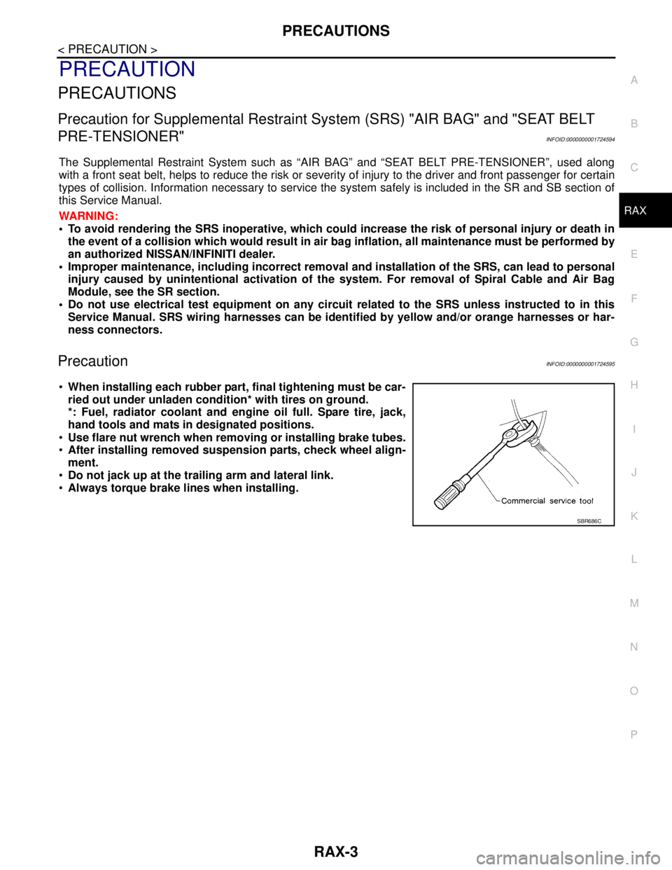
Use flare nut wrench when removing or installing brake tubes.
After installing removed suspension parts, check wheel align-
ment.
Do not jack up at the trailing arm and lateral link.
Always torque brake lines when installing.
SBR686C
Page 4583 of 5883

REAR SUSPENSION BEAM
RSU-11
< ON-VEHICLE REPAIR >
C
D
F
G
H
I
J
K
L
MA
B
RSU
N
O
P
REAR SUSPENSION BEAM
Removal and InstallationINFOID:0000000001724580
REMOVAL
1. Remove rear tires from vehicle using power tool.
2. Separate parking brake rear cable from rear drum brake and rear suspension beam. Refer to PB-4, "
On-
Vehicle Service" .
3. Remove wheel sensor and wheel sensor harness from wheel hub and bearing assembly and rear suspen-
sion beam. Refer to BRC-83, "
Removal and Installation" .
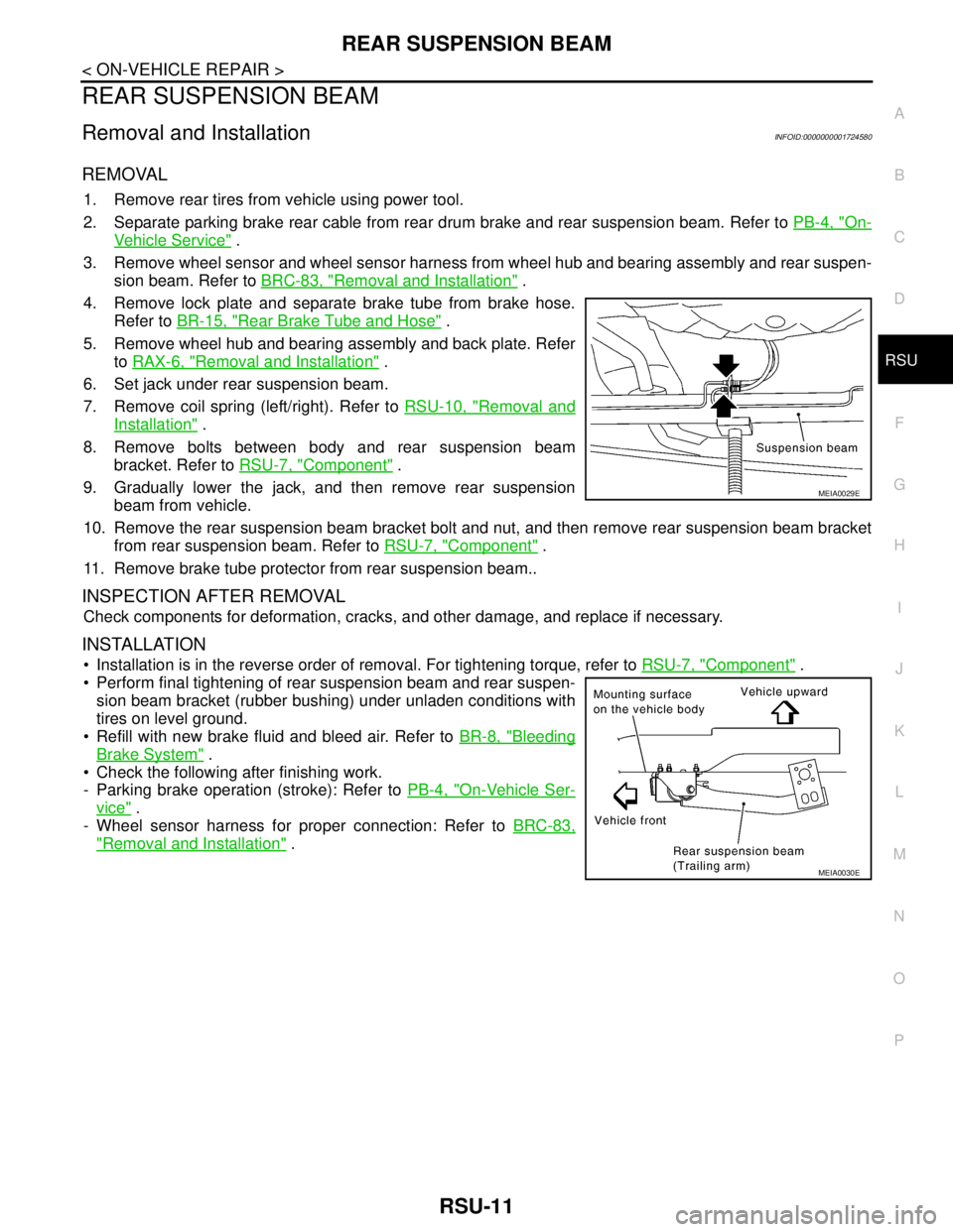
4. Remove lock plate and separate brake tube from brake hose.
Refer to BR-15, "
Rear Brake Tube and Hose" .
5. Remove wheel hub and bearing assembly and back plate. Refer
to RAX-6, "
Removal and Installation" .
6. Set jack under rear suspension beam.
7. Remove coil spring (left/right). Refer to RSU-10, "
Removal and
Installation" .
8. Remove bolts between body and rear suspension beam
bracket. Refer to RSU-7, "
Component" .
9. Gradually lower the jack, and then remove rear suspension
beam from vehicle.
10. Remove the rear suspension beam bracket bolt and nut, and then remove rear suspension beam bracket
from rear suspension beam. Refer to RSU-7, "
Component" .
11. Remove brake tube protector from rear suspension beam..
INSPECTION AFTER REMOVAL
Check components for deformation, cracks, and other damage, and replace if necessary.
INSTALLATION
Installation is in the reverse order of removal. For tightening torque, refer to RSU-7, "Component" .
Perform final tightening of rear suspension beam and rear suspen-
sion beam bracket (rubber bushing) under unladen conditions with
tires on level ground.
Refill with new brake fluid and bleed air. Refer to BR-8, "
Bleeding
Brake System" .
Check the following after finishing work.
- Parking brake operation (stroke): Refer to PB-4, "
On-Vehicle Ser-
vice" .
- Wheel sensor harness for proper connection: Refer to BRC-83,
"Removal and Installation" .
MEIA0029E
MEIA0030E
Page 4634 of 5883
![NISSAN TIIDA 2007 Service Repair Manual INTELLIGENT KEY SYSTEM/ENGINE START FUNCTION
SEC-9
< FUNCTION DIAGNOSIS >[WITH INTELLIGENT KEY SYSTEM]
C
D
E
F
G
H
I
J
L
MA
B
SEC
N
O
P
Intelligent Key has 2 IDs (for Intelligent Key and for NATS). NISSAN TIIDA 2007 Service Repair Manual INTELLIGENT KEY SYSTEM/ENGINE START FUNCTION
SEC-9
< FUNCTION DIAGNOSIS >[WITH INTELLIGENT KEY SYSTEM]
C
D
E
F
G
H
I
J
L
MA
B
SEC
N
O
P
Intelligent Key has 2 IDs (for Intelligent Key and for NATS).](/manual-img/5/57395/w960_57395-4633.png)
INTELLIGENT KEY SYSTEM/ENGINE START FUNCTION
SEC-9
< FUNCTION DIAGNOSIS >[WITH INTELLIGENT KEY SYSTEM]
C
D
E
F
G
H
I
J
L
MA
B
SEC
N
O
P
Intelligent Key has 2 IDs (for Intelligent Key and for NATS). It can perform the door lock/unlock operation and
the engine start operation when the registered Intelligent Key is carried.
When the Intelligent Key battery is discharged, it can be used as emergency back-up by inserting the
mechanical key set in the Intelligent Key to the ignition key cylinder. At that time, perform the NATS ID verifi-
cation. If it is used when the Intelligent Key is carried, perform the Intelligent Key ID verification.
If the ID is successfully verified, and when the ignition knob switch is pressed, steering lock will be released
and initiating the engine will be possible.
The door lock/unlock operation can be performed when the Intelligent Key battery is discharged, by operat-
ing the driver door key cylinder using the mechanical key set in the Intelligent Key.
Up to 4 Intelligent Keys can be registered (including the standard Intelligent Key) on request from the owner.
NOTE:
Refer to XX-XX, "*****"
for any functions other than engine start function of Intelligent Key system.
PRECAUTIONS FOR INTELLIGENT KEY SYSTEM
In the Intelligent Key system, the transponder [the chip for NATS ID verification] is integrated into the
Intelligent Key. (For non-Intelligent Key systems, it is integrated into the mechanical key.) Therefore,
the mechanical key cannot perform the ID verification, and thus it cannot start the engine. Instead,
the NATS ID verification can be performed by inserting the mechanical key into the key cylinder, and
then it can start the engine.
OPERATION WHEN INTELLIGENT KEY IS CARRIED
1. When the ignition knob switch and brake switch are ON, and Intelligent Key unit is transmitting the request
signal to the Intelligent Key.
2. The Intelligent Key receives the request signal and transmits the Intelligent Key ID signal to the Intelligent
Key unit.
3. The Intelligent Key unit receives the Intelligent Key ID signal and verifies it with the registered ID.
4. Intelligent Key unit transmits the steering lock unlock signal to steering lock unit and turn on the key warn-
ing lamp (green) if the verification results are OK. (The detail of key warning lamp operation, refer to XX-
XX, "*****")
5. Release of the steering lock.
6. BCM transmits the starter request signal via CAN communication to IPDM E/R and turns the starter relay
in IPDM E/R ON if BCM judges that the engine start condition is satisfied.
7. IPDM E/R turns the starter control relay ON when receiving the starter request signal.
8. When shift position is in P or N position, battery power is supplied through the starter relay and operate
the starter motor and to start the cranking.
CAUTION:
If a malfunction is detected in the Intelligent Key system, the “KEY” warning lamp in the combina-
tion meter illuminates. At that time, the engine cannot be started.
OPERATION RANGE
Engine can be started when Intelligent Key is inside the vehicle. However, sometimes engine might not start
when Intelligent Key is on instrument panel or in glove box.
OPERATION WHEN MECHANICAL KEY IS USED
When the Intelligent Key battery is discharged, performs the NATS ID verification between the integrated tran-
sponder and BCM by inserting the mechanical key into the key cylinder, and then the engine can be started.
For details relating to starting the engine using mechanical key, refer to SEC-12, "
System Description".
STEERING LOCK OPERATION
Steering is locked by steering lock unit when ignition switch is in the OFF position (the ignition knob is
released) and key switch is OFF (key is removed from ignition key cylinder).
KEY INTERLOCK OPERATION (ONLY FOR M/T MODELS)
In case of a M/T vehicle is in motion and ignition is turned into LOCK position, steering lock unit causes a risk
by activating the steering lock actuator. The key interlock operation is designed to override the steering lock
system and prevent the situation mentioned above from occuring.
LOCK condition
When the following conditions are fulfilled, key interlock solenoid will be locked. (Steering lock inactive)
1 second passes after ignition switch is in ON position and engine revolution speed goes above 500 rpm.
UNLOCK condition
Page 4670 of 5883
![NISSAN TIIDA 2007 Service Repair Manual STOP LAMP SWITCH (A/T)
SEC-45
< COMPONENT DIAGNOSIS >[WITH INTELLIGENT KEY SYSTEM]
C
D
E
F
G
H
I
J
L
MA
B
SEC
N
O
P
STOP LAMP SWITCH (A/T)
Diagnosis ProcedureINFOID:0000000001532059
1.CHECK STOP LAMP NISSAN TIIDA 2007 Service Repair Manual STOP LAMP SWITCH (A/T)
SEC-45
< COMPONENT DIAGNOSIS >[WITH INTELLIGENT KEY SYSTEM]
C
D
E
F
G
H
I
J
L
MA
B
SEC
N
O
P
STOP LAMP SWITCH (A/T)
Diagnosis ProcedureINFOID:0000000001532059
1.CHECK STOP LAMP](/manual-img/5/57395/w960_57395-4669.png)
STOP LAMP SWITCH (A/T)
SEC-45
< COMPONENT DIAGNOSIS >[WITH INTELLIGENT KEY SYSTEM]
C
D
E
F
G
H
I
J
L
MA
B
SEC
N
O
P
STOP LAMP SWITCH (A/T)
Diagnosis ProcedureINFOID:0000000001532059
1.CHECK STOP LAMP SWITCH INPUT SIGNAL
1. Turn ignition switch OFF.
2. Disconnect Intelligent Key unit connector.
3. Check voltage between Intelligent Key unit harness connector
M52 terminal 26 and ground.
Is the inspection result normal?
YES >> Stop lamp switch is OK.
NO >> GO TO 2.
2.CHECK STOP LAMP SWITCH POWER SUPPLY CIRCUIT
1. Disconnect stop lamp switch connector.
2. Check voltage between stop lamp switch harness connector
E13 terminal 1 and ground.
Is the inspection result normal?
YES >> GO TO 3.
NO >> Repair or replace harness between stop lamp switch
power supply circuit and fuse.
3.CHECK STOP LAMP SWITCH OPERATION
Check continuity between stop lamp switch terminals 1 and 2.
Is the inspection result normal?
YES >> GO TO 4.
NO >> Replace stop lamp switch.
4.CHECK STOP LAMP SWITCH CIRCUIT
ConnectorTe r m i n a l s
ConditionVoltage (V)
(Approx.)
(+) (-)
M52 26 GroundBrake pedal
depressedBattery volt-
age
Brake pedal
released0
WIIA1207E
1 - Ground : Battery voltage
WIIA1255E
Component Terminals Condition Continuity
Stop lamp
switch12Brake pedal depressed Yes
Brake pedal released No
WIIA1256E