Page 2857 of 5883
![NISSAN TIIDA 2007 Service Repair Manual EM-210
< REMOVAL AND INSTALLATION >[MR18DE]
ENGINE ASSEMBLY
When installation directions are specified, install parts according to the directions. Refer to EM-207, "Com-
ponent".
Prior to installi NISSAN TIIDA 2007 Service Repair Manual EM-210
< REMOVAL AND INSTALLATION >[MR18DE]
ENGINE ASSEMBLY
When installation directions are specified, install parts according to the directions. Refer to EM-207, "Com-
ponent".
Prior to installi](/manual-img/5/57395/w960_57395-2856.png)
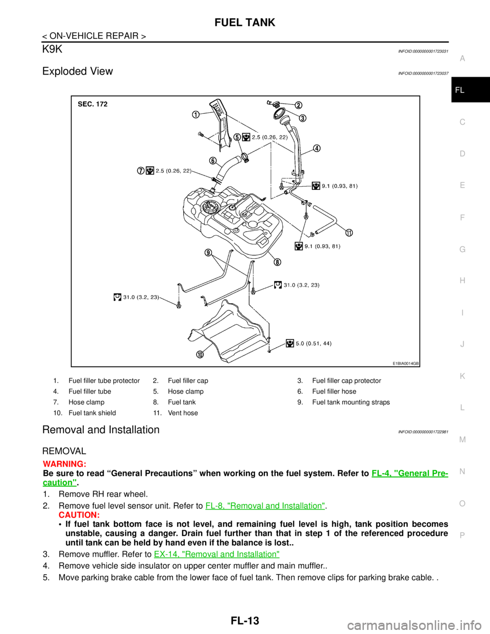
EM-210
< REMOVAL AND INSTALLATION >[MR18DE]
ENGINE ASSEMBLY
When installation directions are specified, install parts according to the directions. Refer to EM-207, "Com-
ponent".
Prior to installing the upper torque rod, apply a light coat of silicone
lubricant (A) to the washer facing side of the bushing inner tube as
shown.
NOTE:
Apply silicone lubricant (A) by dabbing the outward facing tube
surface with a sponge or suitable tool.
Do not apply excess lubricant.
Make sure that each mounting insulator is seated properly, and tighten nuts and bolts.
Tighten engine mounting insulator (RH) bolts in the numerical
order shown.
INSPECTION AFTER INSTALLATION
Inspection for Leaks
The following are procedures for checking fluids leak, lubricates leak and exhaust gases leak.
Before starting engine, check oil/fluid levels including engine coolant and engine oil. If less than required
quantity, fill to the specified level. Refer to LU-15, "
Inspection", CO-35, "Inspection".
Use procedure below to check for fuel leakage.
- Turn ignition switch “ON” (with engine stopped). With fuel pressure applied to fuel piping, check for fuel leak-
age at connection points.
- Start engine. With engine speed increased, check again for fuel leakage at connection points.
Run engine to check for unusual noise and vibration.
Warm up engine thoroughly to make sure there is no leakage of fuel, exhaust gases, or any oil/fluids includ-
ing engine oil and engine coolant.
Bleed air from lines and hoses of applicable lines, such as in cooling system.
After cooling down engine, again check oil/fluid levels including engine oil and engine coolant. Refill to the
specified level, if necessary.
Summary of the inspection items:
* Transmission/transaxle fluid, power steering fluid, brake fluid, etc.: Vehicle front
LBIA0470E
: Vehicle front
WBIA0785E
Item Before starting engine Engine running After engine stopped
Engine coolant Level Leakage Level
Engine oil Level Leakage Level
Other oils and fluid* Level Leakage Level
Fuel Leakage Leakage Leakage
Exhaust gases — Leakage —
Page 3019 of 5883
EXL-18
< FUNCTION DIAGNOSIS >
DAYTIME LIGHT SYSTEM
Component Description
INFOID:0000000001527657
Part Description
BCM Monitors lighting switch position, engine running status and parking brake status to
determine if conditions are set for daytime light system operation.
Requests the IPDM E/R via CAN communication lines to ground the daytime light
relay coil.
IPDM E/RControls ground to the daytime light relay coil based on requests from the BCM (via
CAN communication lines).
Combination switch
(Lighting & turn signal switch)Refer to XX-XX, "*****"
.
Combination meterMonitors engine running status and forwards that information to the BCM via CAN
communication lines.
Page 3075 of 5883

EXL-74
< SYMPTOM DIAGNOSIS >
EXTERIOR LIGHTING SYSTEM SYMPTOMS
Daytime light system does not activate. Either high beam bulb
Parking brake switch
Combination switch
BCM
IPDM E/R
Daytime light relay
Harness between IPDM E/R
and daytime light relay.Daytime light system description.
Refer to XX-XX, "*****"
.
Front fog lamp is not
turned ON.One side Front fog lamp bulb
Harness between IPDM E/R
and the front combination lamp
Front combination lamp
IPDM E/RFront fog lamp circuit
Refer to EXL-41
.
Both sideSymptom diagnosis
"BOTH SIDE FRONT FOG LAMPS ARE NOT TURNED ON"
Refer to EXL-79
.
Parking lamp is not turned
ON.One sideFuse
Parking lamp bulb
Harness between IPDM E/R
and the front/rear combination
lamp
Front/rear combination lamp
IPDM E/RParking lamp circuit
Refer to EXL-46
.
Both sidesSymptom diagnosis
"PARKING, LICENSE PLATE AND TAIL LAMPS ARE NOT TURNED
ON"
Refer to EXL-78
.
Turn signal lamp does not
blink.Indicator lamp is nor-
mal.
(The applicable side
performs the high flash-
er activation). Harness between BCM and
each turn signal lamp
Turn signal lamp bulb
Door mirror (if equipped with
turn signals in the door mirrors)Turn signal lamp circuit
Refer to EXL-52
.
Turn signal indicator lamp
does not blink.One side Combination meter —
Both sides
(Always) Turn signal indicator lamp sig-
nal
Combination meter
BCM Combination meter.
Data monitor "TURN IND"
BCM (FLASHER)
Active test "FLASHER"
Both sides
(Does blink when acti-
vating the hazard warn-
ing lamp with the
ignition switch OFF) The combination meter power
supply and the ground circuit
Combination meterCombination meter
Power supply and the ground circuit
Refer to XX-XX, "*****"
. Symptom Possible cause Inspection item
Page 3173 of 5883

FUEL TANK
FL-13
< ON-VEHICLE REPAIR >
C
D
E
F
G
H
I
J
K
L
MA
FL
N
P O
K9KINFOID:0000000001723031
Exploded ViewINFOID:0000000001723037
Removal and InstallationINFOID:0000000001722981
REMOVAL
WARNING:
Be sure to read “General Precautions” when working on the fuel system. Refer to FL-4, "
General Pre-
caution".
1. Remove RH rear wheel.
2. Remove fuel level sensor unit. Refer to FL-8, "
Removal and Installation".
CAUTION:
If fuel tank bottom face is not level, and remaining fuel level is high, tank position becomes
unstable, causing a danger. Drain fuel further than that in step 1 of the referenced procedure
until tank can be held by hand even if the balance is lost..
3. Remove muffler. Refer to EX-14, "
Removal and Installation"
4. Remove vehicle side insulator on upper center muffler and main muffler..
5. Move parking brake cable from the lower face of fuel tank. Then remove clips for parking brake cable. .
1. Fuel filler tube protector 2. Fuel filler cap 3. Fuel filler cap protector
4. Fuel filler tube 5. Hose clamp 6. Fuel filler hose
7. Hose clamp 8. Fuel tank 9. Fuel tank mounting straps
10. Fuel tank shield 11. Vent hose
E1BIA0014GB
Page 3175 of 5883

FUEL TANK
FL-15
< ON-VEHICLE REPAIR >
C
D
E
F
G
H
I
J
K
L
MA
FL
N
P O
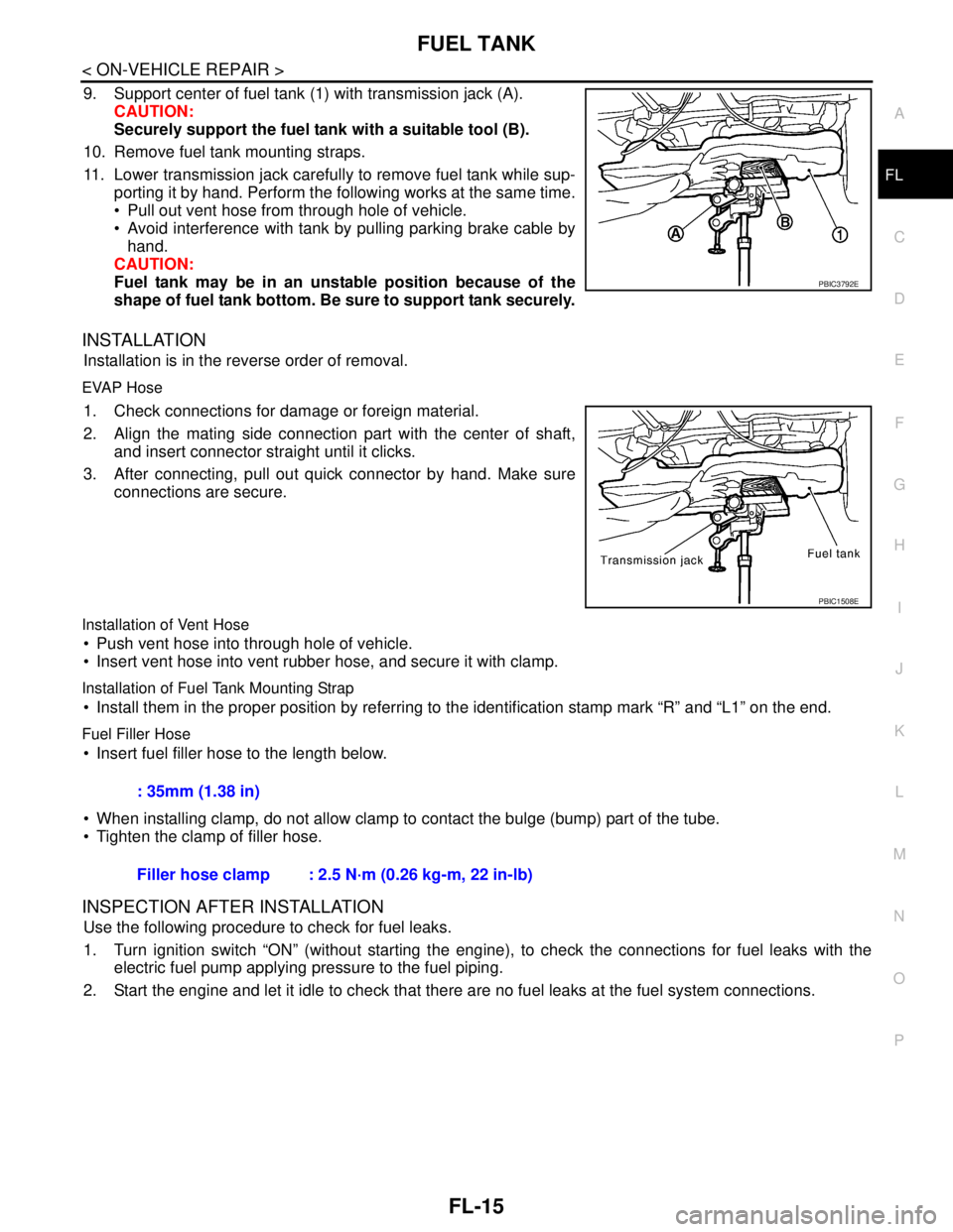
9. Support center of fuel tank (1) with transmission jack (A).
CAUTION:
Securely support the fuel tank with a suitable tool (B).
10. Remove fuel tank mounting straps.
11. Lower transmission jack carefully to remove fuel tank while sup-
porting it by hand. Perform the following works at the same time.
Pull out vent hose from through hole of vehicle.
Avoid interference with tank by pulling parking brake cable by
hand.
CAUTION:
Fuel tank may be in an unstable position because of the
shape of fuel tank bottom. Be sure to support tank securely.
INSTALLATION
Installation is in the reverse order of removal.
EVAP Hose
1. Check connections for damage or foreign material.
2. Align the mating side connection part with the center of shaft,
and insert connector straight until it clicks.
3. After connecting, pull out quick connector by hand. Make sure
connections are secure.
Installation of Vent Hose
Push vent hose into through hole of vehicle.
Insert vent hose into vent rubber hose, and secure it with clamp.
Installation of Fuel Tank Mounting Strap
Install them in the proper position by referring to the identification stamp mark “R” and “L1” on the end.
Fuel Filler Hose
Insert fuel filler hose to the length below.
When installing clamp, do not allow clamp to contact the bulge (bump) part of the tube.
Tighten the clamp of filler hose.
INSPECTION AFTER INSTALLATION
Use the following procedure to check for fuel leaks.
1. Turn ignition switch “ON” (without starting the engine), to check the connections for fuel leaks with the
electric fuel pump applying pressure to the fuel piping.
2. Start the engine and let it idle to check that there are no fuel leaks at the fuel system connections.
PBIC3792E
PBIC1508E
: 35mm (1.38 in)
Filler hose clamp : 2.5 N·m (0.26 kg-m, 22 in-lb)
Page 3244 of 5883

GI-50
< PRECAUTION >
TOW TRUCK TOWING
TOW TRUCK TOWING
Tow Truck TowingINFOID:0000000001606140
CAUTION:
All applicable local laws regarding the towing operation must be obeyed.
It is necessary to use proper towing equipment to avoid possible damage to the vehicle during tow-
ing operation. Towing is in accordance with Towing Procedure Manual at dealer.
Always attach safety chains before towing.
When towing, make sure that the transmission, steering system and power train are in good order. If
any unit is damaged, dollies must be used.
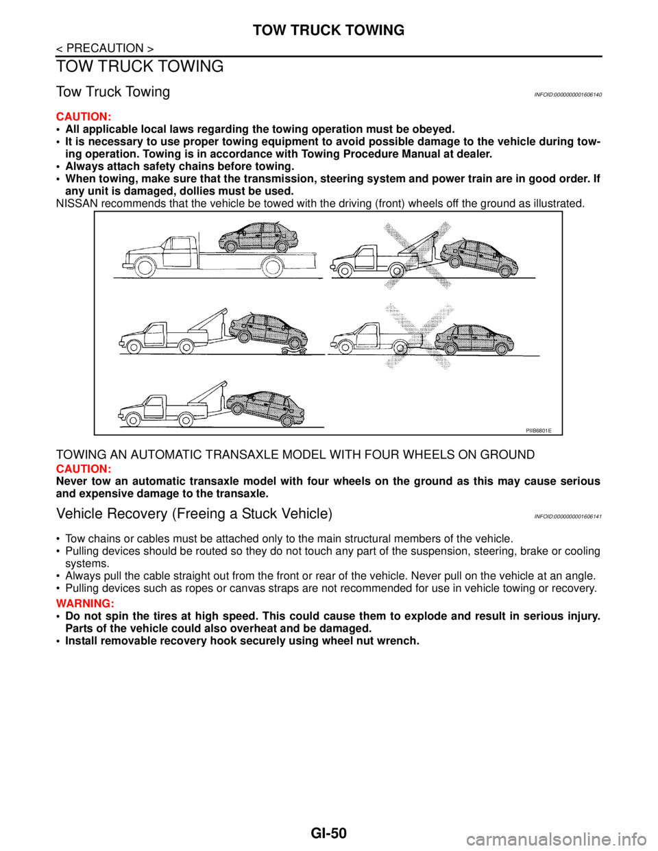
NISSAN recommends that the vehicle be towed with the driving (front) wheels off the ground as illustrated.
TOWING AN AUTOMATIC TRANSAXLE MODEL WITH FOUR WHEELS ON GROUND
CAUTION:
Never tow an automatic transaxle model with four wheels on the ground as this may cause serious
and expensive damage to the transaxle.
Vehicle Recovery (Freeing a Stuck Vehicle)INFOID:0000000001606141
Tow chains or cables must be attached only to the main structural members of the vehicle.
Pulling devices should be routed so they do not touch any part of the suspension, steering, brake or cooling
systems.
Always pull the cable straight out from the front or rear of the vehicle. Never pull on the vehicle at an angle.
Pulling devices such as ropes or canvas straps are not recommended for use in vehicle towing or recovery.
WARNING:
Do not spin the tires at high speed. This could cause them to explode and result in serious injury.
Parts of the vehicle could also overheat and be damaged.
Install removable recovery hook securely using wheel nut wrench.
PIIB6801E
Page 3770 of 5883
LAN-30
< FUNCTION DIAGNOSIS >[CAN]
CAN COMMUNICATION SYSTEM
FUNCTION DIAGNOSIS
CAN COMMUNICATION SYSTEM
CAN System Specification ChartINFOID:0000000001162800
NOTE:
Refer to LAN-22, "
Trouble Diagnosis Procedure" for how to use CAN system specification chart.
Refer to the specification as shown in the chart.
SPECIFICATION CHART A
Determine CAN system type from the following specification chart.
×: Applicable
VEHICLE EQUIPMENT IDENTIFICATION INFORMATION
NOTE:
Body type Hatchback/Sedan
Axle 2WD
Engine K9K HR16DE MR18DE
Transmission M/T A/T M/T
Brake control ABS/ESP
Specification chart SPECIFICATION CHART
ASPECIFICATION CHART BSPECIFICATION CHART
C
Body type Hatchback/Sedan
Axle 2WD
Engine K9K
Transmission M/T
Brake control ABS ESP
Intelligent Key system×× ××
Navigation system××××
CAN system type 12345678
Start CAN Diagnosis
(CONSULT-III)12345678
Page 3771 of 5883
LAN
CAN COMMUNICATION SYSTEM
LAN-31
< FUNCTION DIAGNOSIS >[CAN]
C
D
E
F
G
H
I
J
K
L B A
O
P N
Check CAN system type from the vehicle shape and equipment.
SPECIFICATION CHART B
Determine CAN system type from the following specification chart.
×: Applicable
VEHICLE EQUIPMENT IDENTIFICATION INFORMATION
NOTE:
ALMIA0068GB
Body type Hatchback/Sedan
Axle 2WD
Engine HR16DE
Transmission M/T A/T
Brake control ABS ESP ABS ESP
Intelligent Key system×× ×× ×× ××
Navigation system××××××××
CAN system type 9 101112131415161718192021222324
Start CAN Diagnosis
(CONSULT-III)9 101112131415161718192021222324