Page 3277 of 5883
GW-18
< ON-VEHICLE REPAIR >
REAR WINDOW GLASS AND MOLDING
REAR WINDOW GLASS AND MOLDING
Removal and InstallationINFOID:0000000001716820
Hatchback
LIIA2924E
1. Dam rubber 2. Back door window molding (Lower) 3. Back door window glass
4. Clip (Upper) 5. Clip (Lower) 6. Adhesive
7. Back door outer panel 8. Primer
Page 3278 of 5883

REAR WINDOW GLASS AND MOLDING
GW-19
< ON-VEHICLE REPAIR >
C
D
E
F
G
H
I
J
L
MA
B
GW
N
O
P
Sedan
REMOVAL
1. If equipped, remove the rear wiper arm and motor. Refer to WW-77, "Removal and Installation" .
2. Remove the connectors and grounds for the rear window defogger.
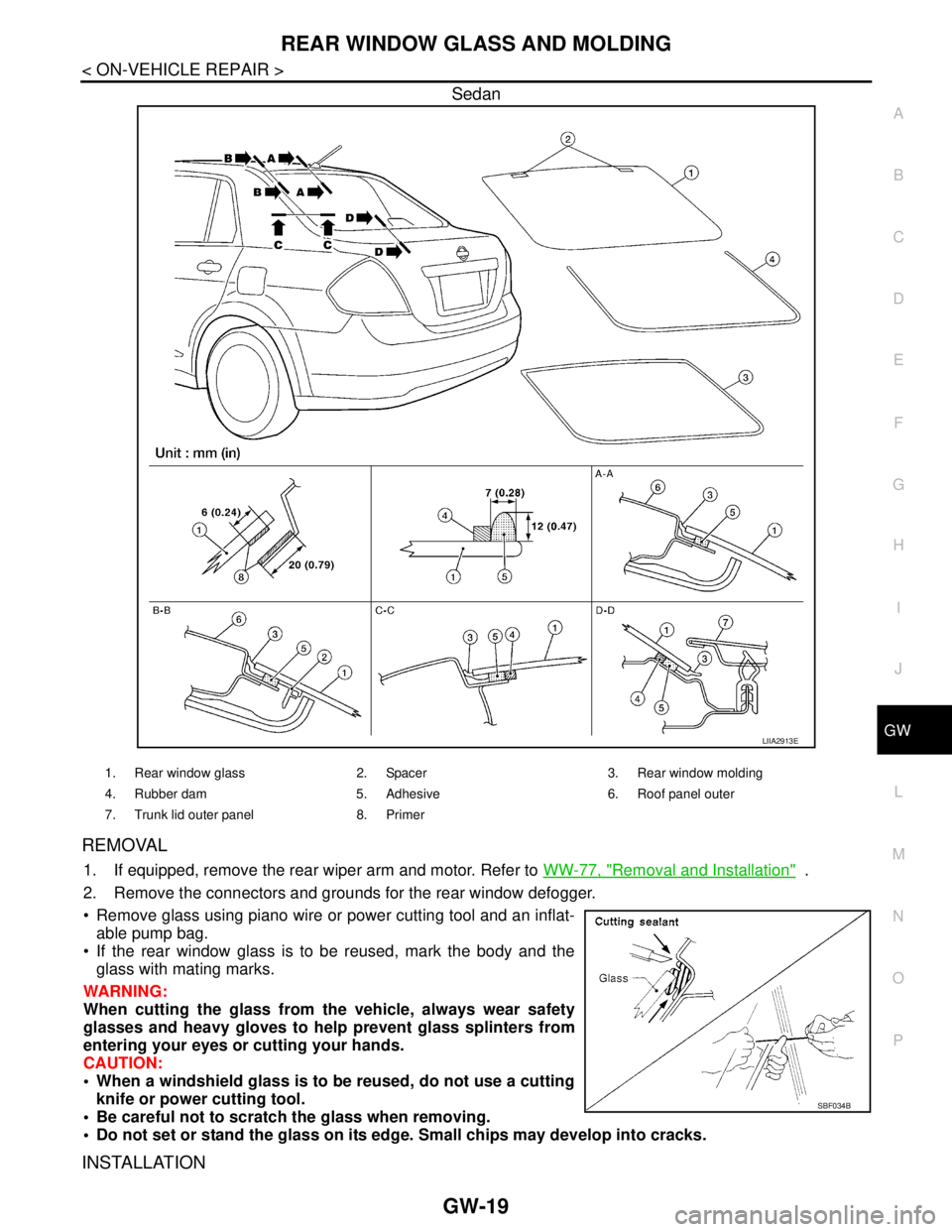
Remove glass using piano wire or power cutting tool and an inflat-
able pump bag.
If the rear window glass is to be reused, mark the body and the
glass with mating marks.
WARNING:
When cutting the glass from the vehicle, always wear safety
glasses and heavy gloves to help prevent glass splinters from
entering your eyes or cutting your hands.
CAUTION:
When a windshield glass is to be reused, do not use a cutting
knife or power cutting tool.
Be careful not to scratch the glass when removing.
Do not set or stand the glass on its edge. Small chips may develop into cracks.
INSTALLATION
LIIA2913E
1. Rear window glass 2. Spacer 3. Rear window molding
4. Rubber dam 5. Adhesive 6. Roof panel outer
7. Trunk lid outer panel 8. Primer
SBF034B
Page 3279 of 5883

GW-20
< ON-VEHICLE REPAIR >
REAR WINDOW GLASS AND MOLDING
Installation is in the reverse order of removal.
Use a genuine NISSAN Urethane Adhesive Kit (if available) or equivalent and follow the instructions fur-
nished with it.
While the urethane adhesive is curing, open a door window. This will prevent the glass from being forced out
by passenger compartment air pressure when a door is closed.
The molding must be installed securely so that it is in position and leaves no gap.
Check gap along bottom to confirm that glass does not contact sheet metal.
Inform the customer that the vehicle should remain stationary until the urethane adhesive has completely
cured (preferably 24 hours). Curing time varies with temperature and humidity.
WARNING:
Keep heat and open flames away as primers and adhesive are flammable.
The materials contained in the kit are harmful if swallowed, and may irritate skin and eyes. Avoid
contact with the skin and eyes.
Use in an open, well ventilated location. Avoid breathing the vapors. They can be harmful if inhaled.
If affected by vapor inhalation, immediately move to an area with fresh air.
Driving the vehicle before the urethane adhesive has completely cured may affect the performance
of the windshield in case of an accident.
CAUTION:
Do not use an adhesive which is past its usable term. Shelf life of this product is limited to six
months after the date of manufacture. Carefully adhere to the expiration or manufacture date printed
on the box.
Keep primers and adhesive in a cool, dry place. Ideally, they should be stored in a refrigerator.
Do not leave primers or adhesive cartridge unattended with their caps open or off.
The vehicle should not be driven for at least 24 hours or until the urethane adhesive has completely
cured. Curing time varies depending on temperature and humidity. The curing time will increase
under lower temperatures and lower humidities.
Repairing Water leaks for Rear Window Glass
Leaks can be repaired without removing or reinstalling glass.
If water is leaking between urethane adhesive material and body or glass, determine the extent of leakage.
This can be done by applying water to the rear window area while pushing glass outward.
To stop leak, apply primer (if necessary) and then urethane adhesive to the leak point.
Page 3280 of 5883
REAR DOOR GLASS AND REGULATOR
GW-21
< ON-VEHICLE REPAIR >
C
D
E
F
G
H
I
J
L
MA
B
GW
N
O
P
REAR DOOR GLASS AND REGULATOR
Removal and InstallationINFOID:0000000001716846
DOOR GLASS
Removal
1. Remove position aside the rear door finisher. Refer to INT-13, "Removal and Installation".
2. Disconnect the harness connector of rear door speaker.
3. Position aside the sealing screen.
NOTE:
If the sealing screen is reused, cut the butyl-tape so that a part of the butyl-tape remains on the sealing
screen.
4. Remove partition sash bolt and screw, pull the partition sash
downward and tilt the upper end of the sash forward to pull out
the sash upward.
1. Door panel 2. Partition sash 3. Door glass run
4. Partition glass weatherstrip 5. Door glass 6. Partition glass
7. Regulator assembly 8. Power window motor (if equipped)
PIIB2634J
PIIB2635J
Page 3281 of 5883

GW-22
< ON-VEHICLE REPAIR >
REAR DOOR GLASS AND REGULATOR
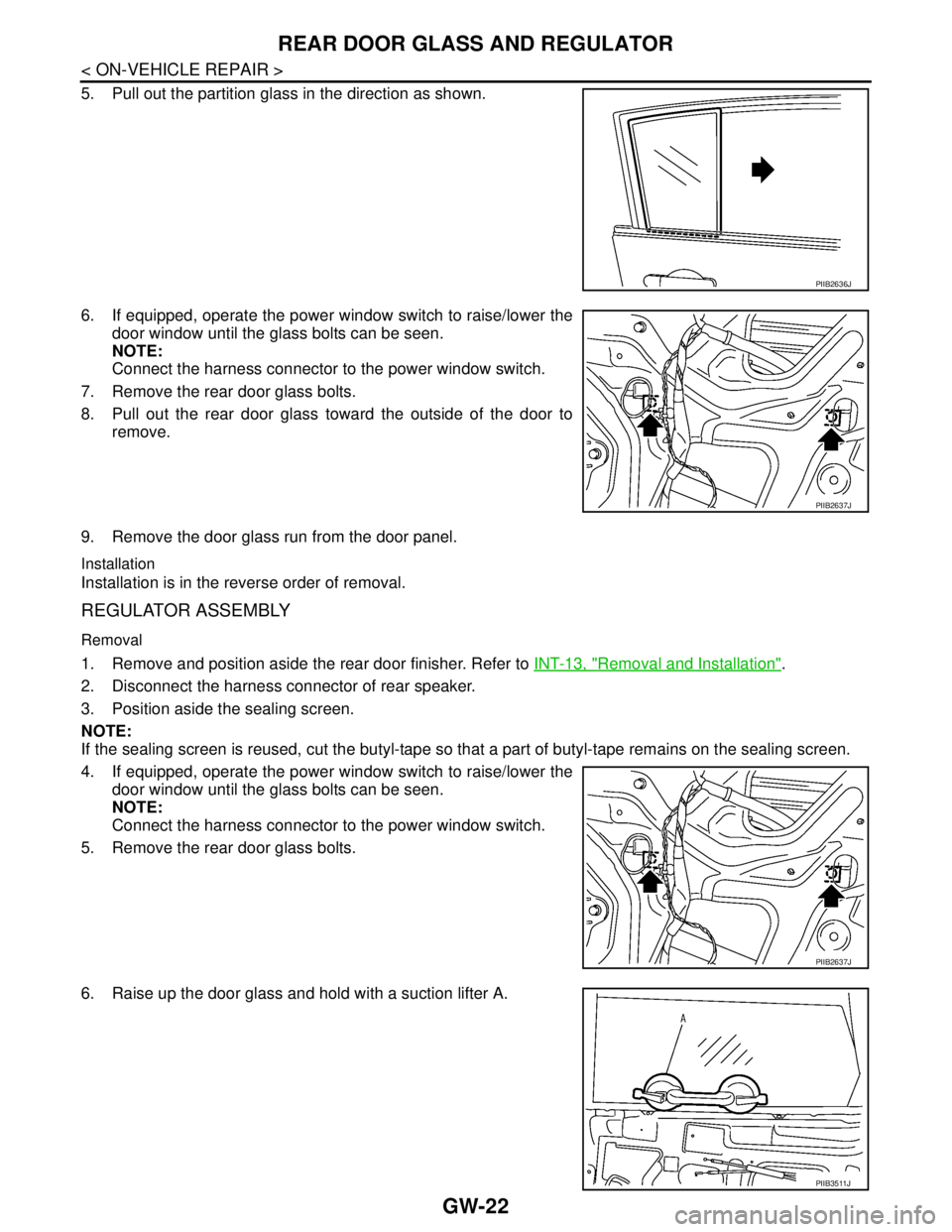
5. Pull out the partition glass in the direction as shown.
6. If equipped, operate the power window switch to raise/lower the
door window until the glass bolts can be seen.
NOTE:
Connect the harness connector to the power window switch.
7. Remove the rear door glass bolts.
8. Pull out the rear door glass toward the outside of the door to
remove.
9. Remove the door glass run from the door panel.
Installation
Installation is in the reverse order of removal.
REGULATOR ASSEMBLY
Removal
1. Remove and position aside the rear door finisher. Refer to INT-13, "Removal and Installation".
2. Disconnect the harness connector of rear speaker.
3. Position aside the sealing screen.
NOTE:
If the sealing screen is reused, cut the butyl-tape so that a part of butyl-tape remains on the sealing screen.
4. If equipped, operate the power window switch to raise/lower the
door window until the glass bolts can be seen.
NOTE:
Connect the harness connector to the power window switch.
5. Remove the rear door glass bolts.
6. Raise up the door glass and hold with a suction lifter A.
PIIB2636J
PIIB2637J
PIIB2637J
PIIB3511J
Page 3282 of 5883

REAR DOOR GLASS AND REGULATOR
GW-23
< ON-VEHICLE REPAIR >
C
D
E
F
G
H
I
J
L
MA
B
GW
N
O
P
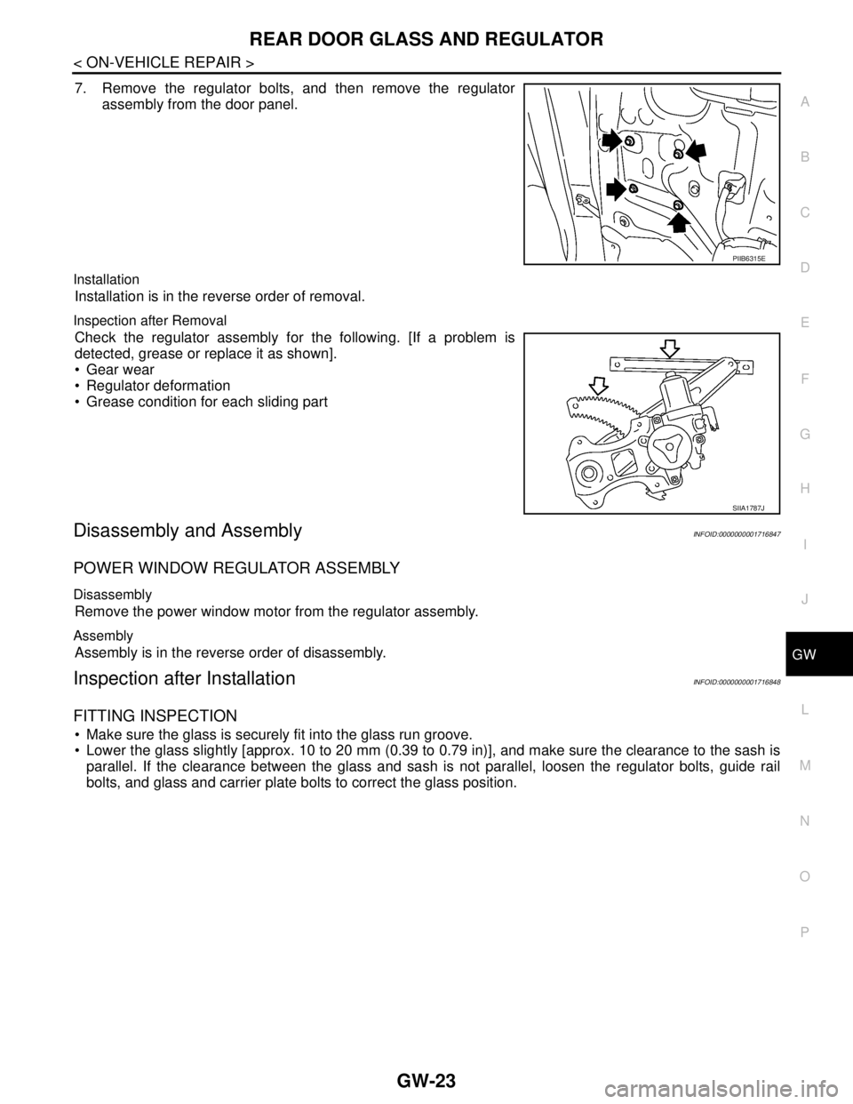
7. Remove the regulator bolts, and then remove the regulator
assembly from the door panel.
Installation
Installation is in the reverse order of removal.
Inspection after Removal
Check the regulator assembly for the following. [If a problem is
detected, grease or replace it as shown].
Gear wear
Regulator deformation
Grease condition for each sliding part
Disassembly and AssemblyINFOID:0000000001716847
POWER WINDOW REGULATOR ASSEMBLY
Disassembly
Remove the power window motor from the regulator assembly.
Assembly
Assembly is in the reverse order of disassembly.
Inspection after InstallationINFOID:0000000001716848
FITTING INSPECTION
Make sure the glass is securely fit into the glass run groove.
Lower the glass slightly [approx. 10 to 20 mm (0.39 to 0.79 in)], and make sure the clearance to the sash is
parallel. If the clearance between the glass and sash is not parallel, loosen the regulator bolts, guide rail
bolts, and glass and carrier plate bolts to correct the glass position.
PIIB6315E
SIIA1787J
Page 3306 of 5883

HA-24
< ON-VEHICLE MAINTENANCE >
FLUORESCENT LEAK DETECTOR
FLUORESCENT LEAK DETECTOR
Checking System for Leaks Using the Fluorescent Leak DetectorINFOID:0000000001396445
1. Check A/C system for leaks using the UV lamp and safety goggles J-42220 in a low sunlight area (area
without windows preferable). Illuminate all components, fittings and lines. The dye will appear as a bright
green/yellow area at the point of leakage. Fluorescent dye observed at the evaporator drain opening indi-
cates an evaporator core assembly (tubes, core or expansion valve) leak.
2. If the suspected area is difficult to see, use an adjustable mirror or wipe the area with a clean shop rag or
cloth, with the UV lamp for dye residue.
3. After the leak is repaired, remove any residual dye using dye cleaner J-43872 to prevent future misdiag-
nosis.
4. Perform a system performance check and verify the leak repair with an approved electronic refrigerant
leak detector.
NOTE:
Other gases in the work area or substances on the A/C components, for example, anti-freeze, windshield
washer fluid, solvents and oils, may falsely trigger the leak detector. Make sure the surfaces to be checked are
clean.
Clean with a dry cloth or blow off with shop air.
Do not allow the sensor tip of the detector to contact with any substance. This can also cause false readings
and may damage the detector.
Dye InjectionINFOID:0000000001396446
(This procedure is only necessary when recharging the system or when the compressor has seized and was
replaced.)
1. Check A/C system static (at rest) pressure. Pressure must be at least 345 kPa (3.45 bar, 3.52 kg/cm
2, 50
psi).
2. Pour one bottle (1/4 ounce / 7.4 cc) of the A/C refrigerant dye into the injector tool J-41459.
3. Connect the injector tool to the A/C low-pressure side service fitting.
4. Start engine and switch A/C ON.
5. When the A/C operating (compressor running), inject one bottle (1/4 ounce / 7.4 cc) of fluorescent dye
through the low-pressure service valve using dye injector tool J-41459 (refer to the manufacture’s operat-
ing instructions).
6. With the engine still running, disconnect the injector tool from the service fitting.
CAUTION:
Be careful the A/C system or replacing a component, pour the dye directly into the open system
connection and proceed with the service procedures.
7. Operate the A/C system for a minimum of 20 minutes to mix the dye with the system oil. Depending on the
leak size, operating conditions and location of the leak, it may take from minutes to days for the dye to
penetrate a leak and become visible.
Page 3344 of 5883
![NISSAN TIIDA 2007 Service Repair Manual AIR CONDITIONER CONTROL
HAC-11
< FUNCTION DIAGNOSIS >[MANUAL AIR CONDITIONER]
C
D
E
F
G
H
J
K
L
MA
B
HAC
N
O
P
AIR CONDITIONER CONTROL
System DiagramINFOID:0000000001203055
System DescriptionINFOID:00 NISSAN TIIDA 2007 Service Repair Manual AIR CONDITIONER CONTROL
HAC-11
< FUNCTION DIAGNOSIS >[MANUAL AIR CONDITIONER]
C
D
E
F
G
H
J
K
L
MA
B
HAC
N
O
P
AIR CONDITIONER CONTROL
System DiagramINFOID:0000000001203055
System DescriptionINFOID:00](/manual-img/5/57395/w960_57395-3343.png)
AIR CONDITIONER CONTROL
HAC-11
< FUNCTION DIAGNOSIS >[MANUAL AIR CONDITIONER]
C
D
E
F
G
H
J
K
L
MA
B
HAC
N
O
P
AIR CONDITIONER CONTROL
System DiagramINFOID:0000000001203055
System DescriptionINFOID:0000000001203056
BLOWER CONTROL DIAL
This dial turns the fan ON and OFF, and controls fan speed.
TEMPERATURE CONTROL DIAL
This dial allows you to adjust the temperature of the discharge air.
MODE DOOR CONTROL DIAL
This dial controls the outlet air flow.
INTAKE DOOR LEVER
Recirculation (REC) position: Interior air is recirculated inside the vehicle.
Fresh (FRE) position: Outside air is drawn into the passenger compartment.
REAR WINDOW DEFOGGER SWITCH
When illumination is ON, rear window is defogged.
A/C SWITCH (IF EQUIPPED)
The A/C switch controls the air conditioner system. When the switch is depressed with the fan ON, the com-
pressor will turn ON. The indicator lamp also illuminates.
Discharge Air FlowINFOID:0000000001547285
1. Intake door lever 2. Mode door control dial 3. Rear window defogger switch
4. Blower control dial 5. A/C switch (if equipped) 6. Temperature control dial
WJIA2189E