2007 NISSAN TIIDA window
[x] Cancel search: windowPage 2322 of 5883
![NISSAN TIIDA 2007 Service Repair Manual ELECTRICAL LOAD SIGNAL
EC-973
< COMPONENT DIAGNOSIS >[MR18DE]
C
D
E
F
G
H
I
J
K
L
MA
EC
N
P O
ELECTRICAL LOAD SIGNAL
DescriptionINFOID:0000000001161966
The electrical load signal (Headlamp switch sign NISSAN TIIDA 2007 Service Repair Manual ELECTRICAL LOAD SIGNAL
EC-973
< COMPONENT DIAGNOSIS >[MR18DE]
C
D
E
F
G
H
I
J
K
L
MA
EC
N
P O
ELECTRICAL LOAD SIGNAL
DescriptionINFOID:0000000001161966
The electrical load signal (Headlamp switch sign](/manual-img/5/57395/w960_57395-2321.png)
ELECTRICAL LOAD SIGNAL
EC-973
< COMPONENT DIAGNOSIS >[MR18DE]
C
D
E
F
G
H
I
J
K
L
MA
EC
N
P O
ELECTRICAL LOAD SIGNAL
DescriptionINFOID:0000000001161966
The electrical load signal (Headlamp switch signal, rear window defogger switch signal, etc.) is transferred
through the CAN communication line from BCM to ECM via IPDM E/R.
Component Function CheckINFOID:0000000001161967
1.CHECK REAR WINDOW DEFOGGER SWITCH FUNCTION
1. Turn ignition switch ON.
2. Connect CONSULT-III and select “DATA MONITOR” mode.
3. Select “LOAD SIGNAL” and check indication under the following conditions.
Is the inspection result normal?
YES >> GO TO 2.
NO >> Go to EC-973, "
Diagnosis Procedure".
2.CHECK LIGHTING SWITCH FUNCTION
Check “LOAD SIGNAL” indication under the following conditions.
Is the inspection result normal?
YES >> GO TO 3.
NO >> Go to EC-973, "
Diagnosis Procedure".
3.CHECK HEATER FAN CONTROL SWITCH FUNCTION
Select “HEATER FAN SW” and check indication under the following conditions.
Is the inspection result normal?
YES >> INSPECTION END
NO >> Go to EC-973, "
Diagnosis Procedure".
Diagnosis ProcedureINFOID:0000000001161968
1.INSPECTION START
Confirm the malfunctioning circuit (rear window defogger, headlamp or heater fan). Refer to EC-973, "
Compo-
nent Function Check".
Which circuit is related to the incident?
Rear window defogger>>GO TO 2
Headlamp>>GO TO 3.
Heater fan>>GO TO 4.
2.CHECK REAR WINDOW DEFOGGER SYSTEM
Refer to DEF-6, "
System Diagram".
Monitor item Condition Indication
LOAD SIGNAL Rear window defogger switchON ON
OFF OFF
Monitor item Condition Indication
LOAD SIGNAL Lighting switchON at 2nd position ON
OFF OFF
Monitor item Condition Indication
HEATER FAN SW Heater fan control switchON ON
OFF OFF
Page 2340 of 5883
![NISSAN TIIDA 2007 Service Repair Manual ECM
EC-991
< ECU DIAGNOSIS >[MR18DE]
C
D
E
F
G
H
I
J
K
L
MA
EC
N
P O
AIR COND SIG Engine: After warming up, idle the
engineAir conditioner switch: OFF OFF
Air conditioner switch: ON
(Compressor oper NISSAN TIIDA 2007 Service Repair Manual ECM
EC-991
< ECU DIAGNOSIS >[MR18DE]
C
D
E
F
G
H
I
J
K
L
MA
EC
N
P O
AIR COND SIG Engine: After warming up, idle the
engineAir conditioner switch: OFF OFF
Air conditioner switch: ON
(Compressor oper](/manual-img/5/57395/w960_57395-2339.png)
ECM
EC-991
< ECU DIAGNOSIS >[MR18DE]
C
D
E
F
G
H
I
J
K
L
MA
EC
N
P O
AIR COND SIG Engine: After warming up, idle the
engineAir conditioner switch: OFF OFF
Air conditioner switch: ON
(Compressor operates.)ON
P/N POSI SW Ignition switch: ONShift lever: Neutral ON
Selector lever: Except above OFF
PW/ST SIGNAL Engine: After warming up, idle the
engineSteering wheel: Not being turned OFF
Steering wheel: Being turned ON
LOAD SIGNAL Ignition switch: ONRear window defogger switch: ON
and/or Lighting switch: 2nd positionON
Rear window defogger switch and lighting
switch: OFFOFF
IGNITION SW Ignition switch: ON → OFF → ON ON → OFF → ON
HEATER FAN SW Engine: After warming up, idle the
engineHeater fan switch: ON ON
Heater fan switch: OFF OFF
BRAKE SW Ignition switch: ONBrake pedal: Fully released OFF
Brake pedal: Slightly depressed ON
INJ PULSE-B1 Engine: After warming up
Shift lever:Neutral
Air conditioner switch: OFF
No loadIdle 2.0 - 3.0 msec
2,000 rpm 1.9 - 2.9 msec
IGN TIMING Engine: After warming up
Shift lever:Neutral
Air conditioner switch: OFF
No loadIdle 10° - 20° BTDC
2,000 rpm 25° - 45° BTDC
PURG VOL C/V Engine: After warming up
Shift lever:Neutral
Air conditioner switch: OFF
No loadIdle 0%
2,000 rpm 20% - 90%
INT/V TIM (B1) Engine: After warming up
Shift lever:Neutral
Air conditioner switch: OFF
No loadIdle−5° - 5°CA
2,000 rpm Approx. 0° - 20°CA
INT/V SOL (B1) Engine: After warming up
Shift lever:Neutral
Air conditioner switch: OFF
No loadIdle 0%
2,000 rpm Approx. 0% - 60%
AIR COND RLY Engine: After warming up, idle the
engineAir conditioner switch: OFF OFF
Air conditioner switch: ON
(Compressor operates)ON
FUEL PUMP RLY For 1 seconds after turning ignition switch: ON
Engine running or crankingON
Except above OFF
THRTL RELAY Ignition switch: ON ON
COOLING FAN Engine: After warming up, idle the
engine
Air conditioner switch: OFFEngine coolant temperature is 97 °C
(207°F) or less.OFF
Engine coolant temperature is between
98°C (208°F) and 99°C (210°F)LOW
Engine coolant temperature is 100°C
(212°F) or moreHIGH
HO2S1 HTR (B1) Engine: After warming up
Engine speed: Above 3,600 rpmON
Engine speed: Above 3,600 rpm OFF Monitor Item Condition Values/Status
Page 2387 of 5883
![NISSAN TIIDA 2007 Service Repair Manual EC-1038
< SERVICE DATA AND SPECIFICATIONS (SDS) [MR18DE]
SERVICE DATA AND SPECIFICATIONS (SDS)
SERVICE DATA AND SPECIFICATIONS (SDS)
SERVICE DATA AND SPECIFICATIONS (SDS)
Idle SpeedINFOID:000000000116 NISSAN TIIDA 2007 Service Repair Manual EC-1038
< SERVICE DATA AND SPECIFICATIONS (SDS) [MR18DE]
SERVICE DATA AND SPECIFICATIONS (SDS)
SERVICE DATA AND SPECIFICATIONS (SDS)
SERVICE DATA AND SPECIFICATIONS (SDS)
Idle SpeedINFOID:000000000116](/manual-img/5/57395/w960_57395-2386.png)
EC-1038
< SERVICE DATA AND SPECIFICATIONS (SDS) [MR18DE]
SERVICE DATA AND SPECIFICATIONS (SDS)
SERVICE DATA AND SPECIFICATIONS (SDS)
SERVICE DATA AND SPECIFICATIONS (SDS)
Idle SpeedINFOID:0000000001162007
*: Under the following conditions
A/C switch: OFF
Electric load: OFF (Lights, heater fan & rear window defogger)
Steering wheel: Kept in straight-ahead position
Ignition TimingINFOID:0000000001162008
*: Under the following conditions
A/C switch: OFF
Electric load: OFF (Lights, heater fan & rear window defogger)
Steering wheel: Kept in straight-ahead position
Calculated Load ValueINFOID:0000000001162009
Mass Air Flow SensorINFOID:0000000001162010
*: Engine is warmed up to normal operating temperature and running under no load.Condition Specification
No load* (in Neutral position) 700 ± 50 rpm
Condition Specification
No load* (in Neutral position) 15 ± 5° BTDC
Condition Specification (Using CONSULT-III or GST)
At idle10 – 35 %
At 2,500 rpm10 – 35 %
Supply voltageBattery voltage (11 – 14 V)
Output voltage at idle0.8 – 1.1V*
Mass air flow (Using CONSULT-III or GST)1.0 – 4.0 g·m/sec at idle*
2.0 – 10.0 g·m/sec at 2,500 rpm*
Page 2647 of 5883
![NISSAN TIIDA 2007 Service Repair Manual EC-1298
< SERVICE DATA AND SPECIFICATIONS (SDS) [K9K]
SERVICE DATA AND SPECIFICATIONS (SDS)
SERVICE DATA AND SPECIFICATIONS (SDS)
SERVICE DATA AND SPECIFICATIONS (SDS)
Idle SpeedINFOID:000000000116274 NISSAN TIIDA 2007 Service Repair Manual EC-1298
< SERVICE DATA AND SPECIFICATIONS (SDS) [K9K]
SERVICE DATA AND SPECIFICATIONS (SDS)
SERVICE DATA AND SPECIFICATIONS (SDS)
SERVICE DATA AND SPECIFICATIONS (SDS)
Idle SpeedINFOID:000000000116274](/manual-img/5/57395/w960_57395-2646.png)
EC-1298
< SERVICE DATA AND SPECIFICATIONS (SDS) [K9K]
SERVICE DATA AND SPECIFICATIONS (SDS)
SERVICE DATA AND SPECIFICATIONS (SDS)
SERVICE DATA AND SPECIFICATIONS (SDS)
Idle SpeedINFOID:0000000001162748
*: Under the following conditions
A/C switch: OFF
Electric load: OFF (Lights, glow plug, heater fan & rear window defogger)
Steering wheel: Kept in straight-ahead positionCondition Specification
No load* (in Neutral position) 800 ± 50 rpm
Page 3130 of 5883

EXT-26
< ON-VEHICLE REPAIR >
DOOR OUTSIDE MOLDING
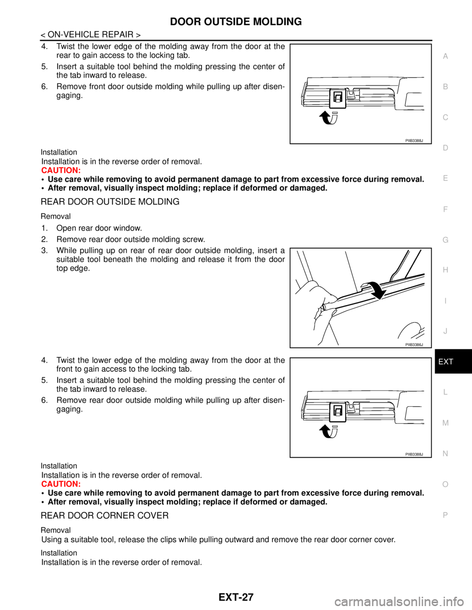
Sedan Models
Removal and InstallationINFOID:0000000001568936
FRONT DOOR OUTSIDE MOLDING
Removal
1. Open front door window.
2. Remove front door outside molding screw.
3. While pulling up on front of front door outside molding, insert a
suitable tool beneath the molding and release it from the door
top edge.
WIIA1411E
1. Front door outside molding 2. Rear door outside molding 3. Rear door corner cover
C. Clip C101
PIIB3386J
Page 3131 of 5883

DOOR OUTSIDE MOLDING
EXT-27
< ON-VEHICLE REPAIR >
C
D
E
F
G
H
I
J
L
MA
B
EXT
N
O
P
4. Twist the lower edge of the molding away from the door at the
rear to gain access to the locking tab.
5. Insert a suitable tool behind the molding pressing the center of
the tab inward to release.
6. Remove front door outside molding while pulling up after disen-
gaging.
Installation
Installation is in the reverse order of removal.
CAUTION:
Use care while removing to avoid permanent damage to part from excessive force during removal.
After removal, visually inspect molding; replace if deformed or damaged.
REAR DOOR OUTSIDE MOLDING
Removal
1. Open rear door window.
2. Remove rear door outside molding screw.
3. While pulling up on rear of rear door outside molding, insert a
suitable tool beneath the molding and release it from the door
top edge.
4. Twist the lower edge of the molding away from the door at the
front to gain access to the locking tab.
5. Insert a suitable tool behind the molding pressing the center of
the tab inward to release.
6. Remove rear door outside molding while pulling up after disen-
gaging.
Installation
Installation is in the reverse order of removal.
CAUTION:
Use care while removing to avoid permanent damage to part from excessive force during removal.
After removal, visually inspect molding; replace if deformed or damaged.
REAR DOOR CORNER COVER
Removal
Using a suitable tool, release the clips while pulling outward and remove the rear door corner cover.
Installation
Installation is in the reverse order of removal.
PIIB3388J
PIIB3386J
PIIB3388J
Page 3221 of 5883

RECOMMENDED CHEMICAL PRODUCTS AND SEALANTS
GI-27
< HOW TO USE THIS MANUAL >
C
D
E
F
G
H
I
J
K
L
MB
GI
N
O
PRECOMMENDED CHEMICAL PRODUCTS AND SEALANTS
Recommended Chemical Products and SealantsINFOID:0000000001691465
Refer to the following chart for help in selecting the appropriate chemical product or sealant.
Product Description PurposeNissan North America
Part No. (USA)Nissan Canada Part
No. (Canada)Aftermarket Cross-
reference Part Nos.
1Rear View Mirror Adhe-
siveUsed to permanently re-
mount rear view mirrors to
windows.999MP-AM000P 99998-50505 Permatex 81844
2Anaerobic Liquid Gas-
ketFor metal-to-metal flange
sealing.
Can fill a 0.38 mm (0.015
inch) gap and provide in-
stant sealing for most pow-
ertrain applications.999MP-AM001P 99998-50503Permatex 51813 and
51817
3High Performance
Thread SealantProvides instant sealing on
any threaded straight or
parallel threaded fitting.
(Thread sealant only, no
locking ability.)
Do not use on plastic.999MP-AM002P 999MP-AM002P Permatex 56521
4 Silicone RTVGasket Maker999MP-AM003P
(Ultra Grey)99998-50506
(Ultra Grey)Permatex Ultra Grey
82194;
Three Bond
1207,1215, 1216,
1217F, 1217G and
1217H
Nissan RTV Part No.
999MP-A7007
Gasket Maker for Maxima/
Quest 5-speed automatic
transmission
(RE5F22A)––Three Bond 1281B
or exact equivalent in
its quality
5High Temperature,
High Strength Thread
Locking Sealant (Red)Threadlocker 999MP-AM004P 999MP-AM004PPermatex 27200;
Three Bond 1360,
1360N, 1305 N&P,
1307N, 1335,
1335B, 1363B,
1377C, 1386B, D&E
and 1388
Loctite 648
6Medium Strength
Thread Locking Seal-
ant (Blue)Threadlocker (service tool
removable)999MP-AM005P 999MP-AM005PPermatex 24200,
24206, 24240,
24283 and 09178;
Three Bond 1322,
1322N, 1324 D&N,
1333D, 1361C,
1364D, 1370C and
1374
Page 3251 of 5883

SERVICE INFORMATION FOR ELECTRICAL INCIDENT
GI-57
< BASIC INSPECTION >
C
D
E
F
G
H
I
J
K
L
MB
GI
N
O
P
An unclamped or loose harness can cause wiring to be pinched by seat components (such as slide guides)
during vehicle vibration. If the wiring runs under seating areas, inspect wire routing for possible damage or
pinching.
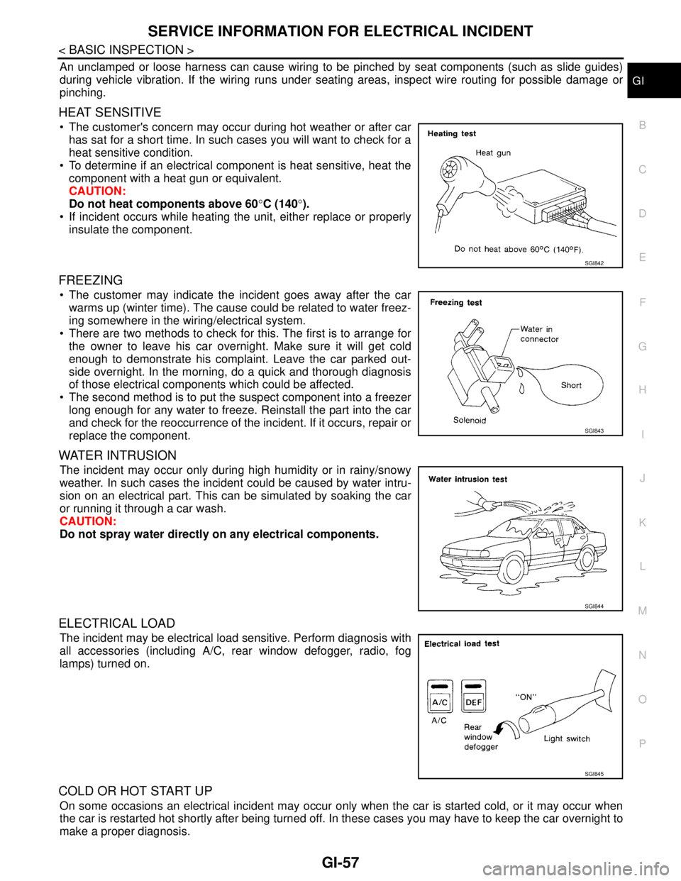
HEAT SENSITIVE
The customer's concern may occur during hot weather or after car
has sat for a short time. In such cases you will want to check for a
heat sensitive condition.
To determine if an electrical component is heat sensitive, heat the
component with a heat gun or equivalent.
CAUTION:
Do not heat components above 60°C (140°).
If incident occurs while heating the unit, either replace or properly
insulate the component.
FREEZING
The customer may indicate the incident goes away after the car
warms up (winter time). The cause could be related to water freez-
ing somewhere in the wiring/electrical system.
There are two methods to check for this. The first is to arrange for
the owner to leave his car overnight. Make sure it will get cold
enough to demonstrate his complaint. Leave the car parked out-
side overnight. In the morning, do a quick and thorough diagnosis
of those electrical components which could be affected.
The second method is to put the suspect component into a freezer
long enough for any water to freeze. Reinstall the part into the car
and check for the reoccurrence of the incident. If it occurs, repair or
replace the component.
WATER INTRUSION
The incident may occur only during high humidity or in rainy/snowy
weather. In such cases the incident could be caused by water intru-
sion on an electrical part. This can be simulated by soaking the car
or running it through a car wash.
CAUTION:
Do not spray water directly on any electrical components.
ELECTRICAL LOAD
The incident may be electrical load sensitive. Perform diagnosis with
all accessories (including A/C, rear window defogger, radio, fog
lamps) turned on.
COLD OR HOT START UP
On some occasions an electrical incident may occur only when the car is started cold, or it may occur when
the car is restarted hot shortly after being turned off. In these cases you may have to keep the car overnight to
make a proper diagnosis.
SGI842
SGI843
SGI844
SGI845