2007 NISSAN TIIDA sensor
[x] Cancel search: sensorPage 4533 of 5883
RAX-6
< ON-VEHICLE REPAIR >
WHEEL HUB
ON-VEHICLE REPAIR
WHEEL HUB
Removal and InstallationINFOID:0000000001724589
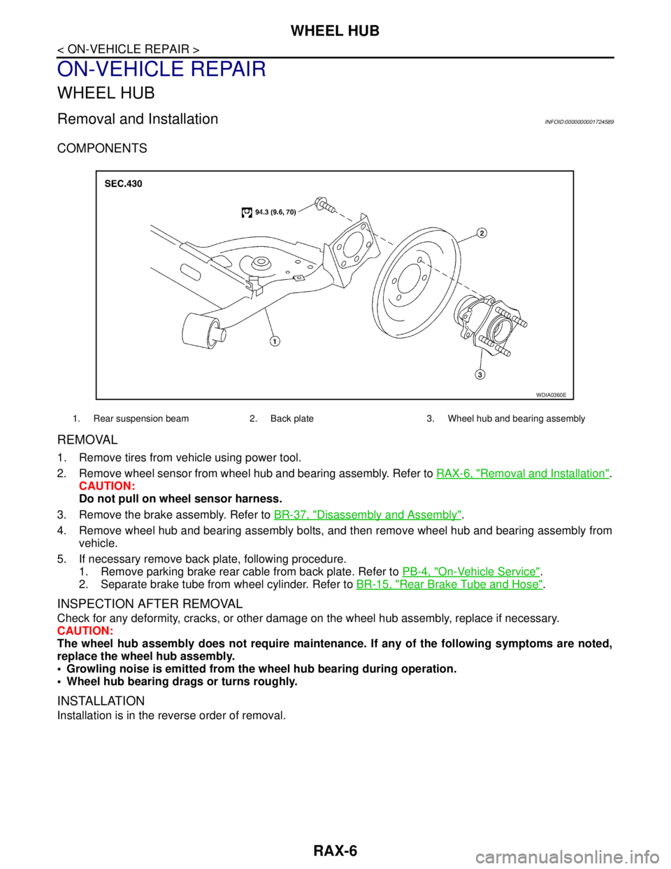
COMPONENTS
REMOVAL
1. Remove tires from vehicle using power tool.
2. Remove wheel sensor from wheel hub and bearing assembly. Refer to RAX-6, "
Removal and Installation".
CAUTION:
Do not pull on wheel sensor harness.
3. Remove the brake assembly. Refer to BR-37, "
Disassembly and Assembly".
4. Remove wheel hub and bearing assembly bolts, and then remove wheel hub and bearing assembly from
vehicle.
5. If necessary remove back plate, following procedure.
1. Remove parking brake rear cable from back plate. Refer to PB-4, "
On-Vehicle Service".
2. Separate brake tube from wheel cylinder. Refer to BR-15, "
Rear Brake Tube and Hose".
INSPECTION AFTER REMOVAL
Check for any deformity, cracks, or other damage on the wheel hub assembly, replace if necessary.
CAUTION:
The wheel hub assembly does not require maintenance. If any of the following symptoms are noted,
replace the wheel hub assembly.
Growling noise is emitted from the wheel hub bearing during operation.
Wheel hub bearing drags or turns roughly.
INSTALLATION
Installation is in the reverse order of removal.
1. Rear suspension beam 2. Back plate 3. Wheel hub and bearing assembly
WDIA0360E
Page 4577 of 5883
REAR SUSPENSION ASSEMBLY
RSU-5
< ON-VEHICLE MAINTENANCE >
C
D
F
G
H
I
J
K
L
MA
B
RSU
N
O
P
ON-VEHICLE MAINTENANCE
REAR SUSPENSION ASSEMBLY
On-Vehicle Inspection and ServiceINFOID:0000000001724575
Make sure the mounting conditions (looseness, backlash) of each component and component conditions
(wear, damage) are within specifications.
SHOCK ABSORBER INSPECTION
Check shock absorber for oil leakage, damage and replace it if necessary.
Wheel AlignmentINFOID:0000000001724576
DESCRIPTION
Measure wheel alignment under unladen conditions.
NOTE:
“Unladen conditions” means that fuel, engine coolant, and lubricant are full. Spare tire, jack, hand tools and
mats are in designated positions.
PRELIMINARY
Check the following:
1. Tires for improper air pressure and wear.
2. Road wheels for runout. Refer to WT-5, "
Inspection" .
3. Wheel bearing axial end play. Refer to RAX-5, "
On-Vehicle Inspection and Service" .
4. Shock absorber operation.
5. Each mounting part of suspension for looseness and deformation.
6. Rear suspension beam for cracks, deformation, and other damage.
7. Vehicle height (posture).
GENERAL INFORMATION AND RECOMMENDATIONS
1. A Four-Wheel Thrust Alignment should be performed.
This type of alignment is recommended for any NISSAN vehicle.
The four-wheel “thrust” process helps ensure that the vehicle is properly aligned and the steering wheel
is centered.
The alignment machine itself should be capable of accepting any NISSAN vehicle.
The alignment machine should be checked to ensure that it is level.
2. Make sure the alignment machine is properly calibrated.
Your alignment machine should be regularly calibrated in order to give correct information.
Check with the manufacturer of your specific alignment machine for their recommended Service/Cali-
bration Schedule.
THE ALIGNMENT PROCESS
IMPORTANT: Use only the alignment specifications listed in this Service Manual. Refer to RSU-5, "Wheel
Alignment" .
1. When displaying the alignment settings, many alignment machines use “indicators”: (Green/red, plus or
minus, Go/No Go). Do NOT use these indicators.
The alignment specifications programmed into your alignment machine that operate these indicators
may not be correct.
This may result in an ERROR.
2. Some newer alignment machines are equipped with an optional “Rolling Compensation” method to “com-
pensate” the sensors (alignment targets or head units). Do NOT use this “Rolling Compensation”
method.
Use the “Jacking Compensation” method. After installing the alignment targets or head units, raise the
vehicle and rotate the wheels 1/2 turn both ways.
See Instructions in the alignment machine you are using for more information.
CAMBER INSPECTION
Page 4580 of 5883
RSU-8
< ON-VEHICLE REPAIR >
SHOCK ABSORBER
ON-VEHICLE REPAIR
SHOCK ABSORBER
Removal and InstallationINFOID:0000000001724578
REMOVAL
1. Remove rear tires from vehicle using power tool.
2. Remove wheel sensor from wheel hub and bearing assembly and rear suspension beam. Refer to BRC-
83, "Removal and Installation" .
CAUTION:
Do not pull on wheel sensor harness.
3. Remove shock absorber mask from trunk side finisher using a flat-bladed screwdriver. Refer to INT-24,
"Removal and Installation" .
CAUTION:
Wrap the tip of a screwdriver with cloth to avoid damaging components.
4. Set jack under rear suspension beam.
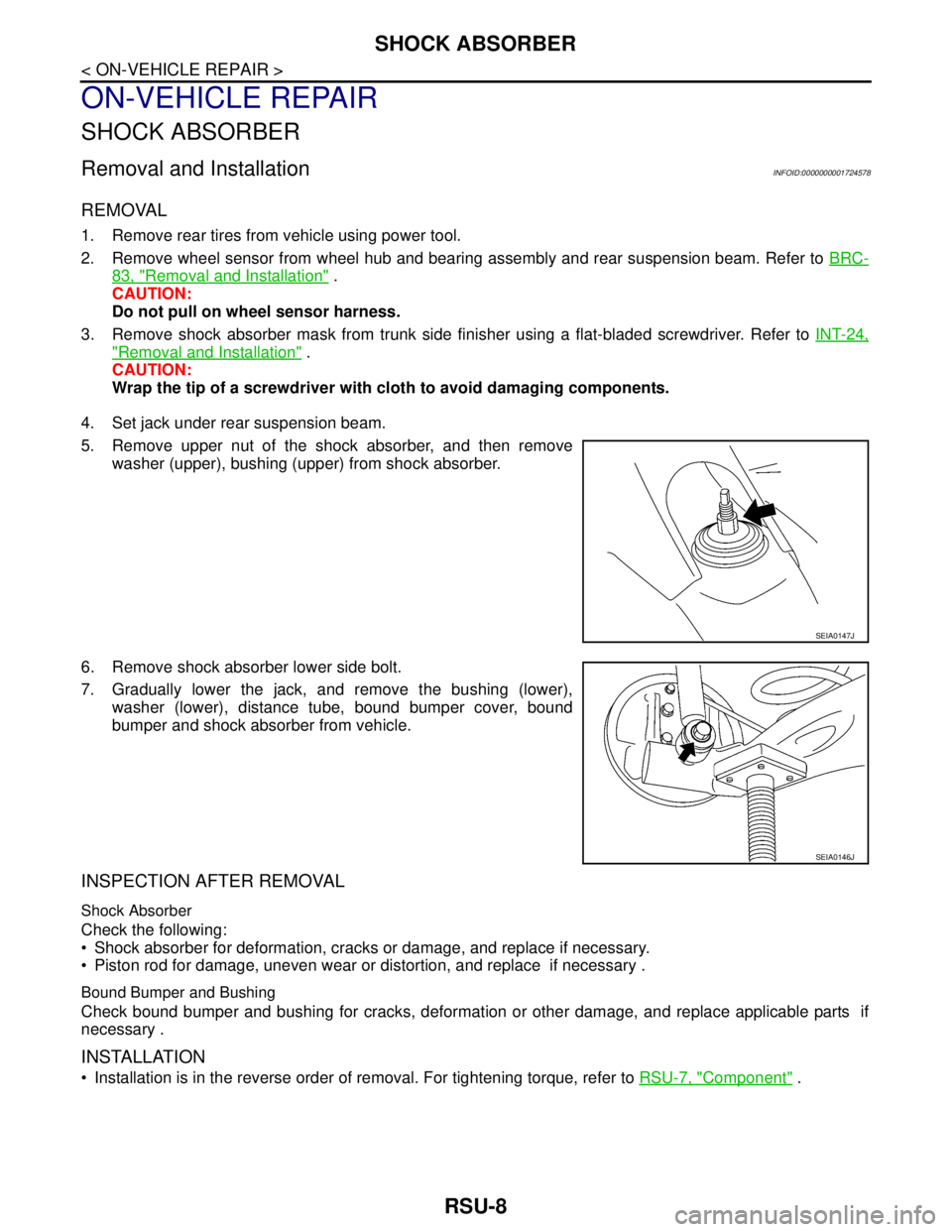
5. Remove upper nut of the shock absorber, and then remove
washer (upper), bushing (upper) from shock absorber.
6. Remove shock absorber lower side bolt.
7. Gradually lower the jack, and remove the bushing (lower),
washer (lower), distance tube, bound bumper cover, bound
bumper and shock absorber from vehicle.
INSPECTION AFTER REMOVAL
Shock Absorber
Check the following:
Shock absorber for deformation, cracks or damage, and replace if necessary.
Piston rod for damage, uneven wear or distortion, and replace if necessary .
Bound Bumper and Bushing
Check bound bumper and bushing for cracks, deformation or other damage, and replace applicable parts if
necessary .
INSTALLATION
Installation is in the reverse order of removal. For tightening torque, refer to RSU-7, "Component" .
SEIA0147J
SEIA0146J
Page 4582 of 5883
RSU-10
< ON-VEHICLE REPAIR >
COIL SPRING
COIL SPRING
Removal and InstallationINFOID:0000000001724579
REMOVAL
1. Remove rear tires from vehicle using power tool.
2. Remove wheel sensor from wheel hub and bearing assembly. Refer to BRC-83, "
Removal and Installa-
tion" .
CAUTION:
Do not pull on wheel sensor harness.
3. Separate brake tube from wheel cylinder. Refer to BR-15, "
Rear Brake Tube and Hose" .
4. Set jack under rear suspension beam.
5. Remove shock absorber lower side bolt. Refer to RSU-8,
"Removal and Installation" .
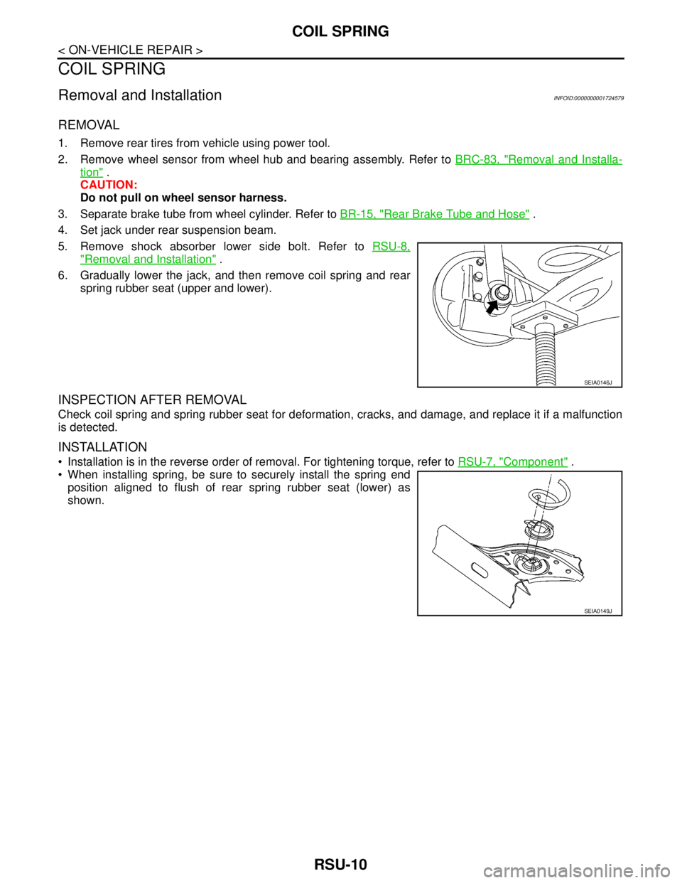
6. Gradually lower the jack, and then remove coil spring and rear
spring rubber seat (upper and lower).
INSPECTION AFTER REMOVAL
Check coil spring and spring rubber seat for deformation, cracks, and damage, and replace it if a malfunction
is detected.
INSTALLATION
Installation is in the reverse order of removal. For tightening torque, refer to RSU-7, "Component" .
When installing spring, be sure to securely install the spring end
position aligned to flush of rear spring rubber seat (lower) as
shown.
SEIA0146J
SEIA0149J
Page 4583 of 5883
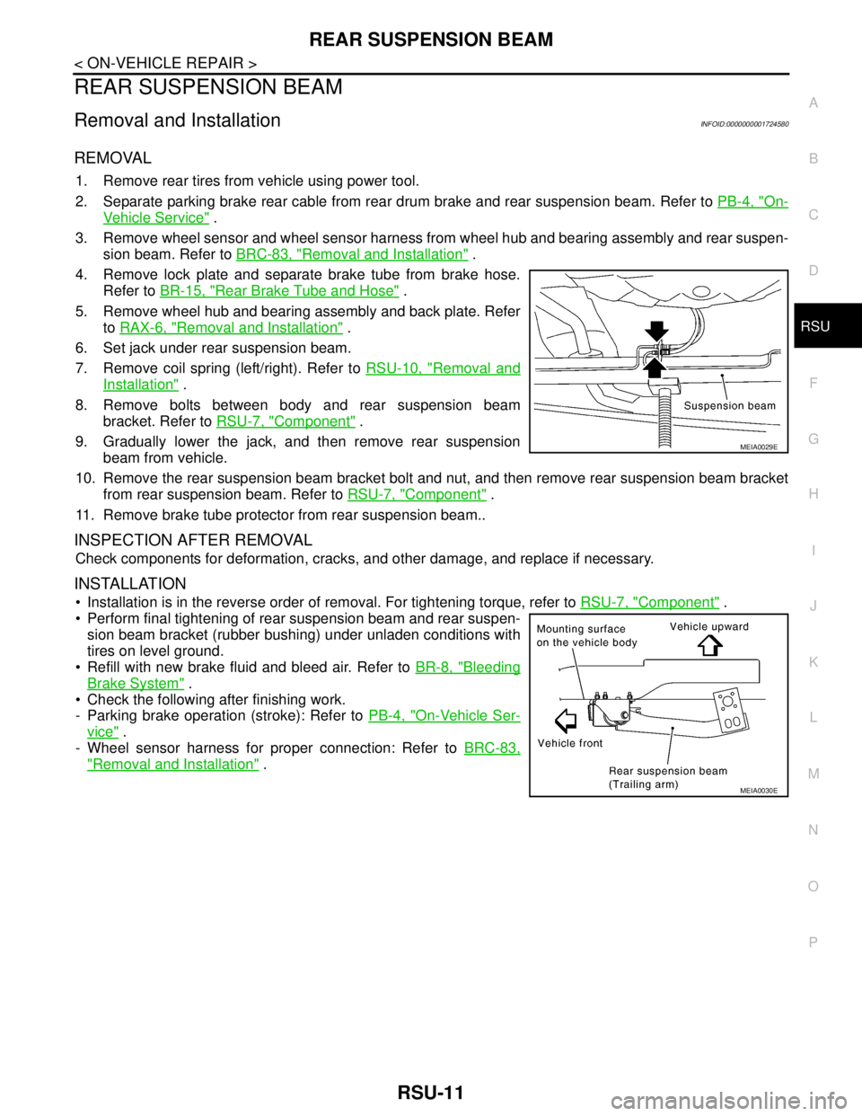
REAR SUSPENSION BEAM
RSU-11
< ON-VEHICLE REPAIR >
C
D
F
G
H
I
J
K
L
MA
B
RSU
N
O
P
REAR SUSPENSION BEAM
Removal and InstallationINFOID:0000000001724580
REMOVAL
1. Remove rear tires from vehicle using power tool.
2. Separate parking brake rear cable from rear drum brake and rear suspension beam. Refer to PB-4, "
On-
Vehicle Service" .
3. Remove wheel sensor and wheel sensor harness from wheel hub and bearing assembly and rear suspen-
sion beam. Refer to BRC-83, "
Removal and Installation" .
4. Remove lock plate and separate brake tube from brake hose.
Refer to BR-15, "
Rear Brake Tube and Hose" .
5. Remove wheel hub and bearing assembly and back plate. Refer
to RAX-6, "
Removal and Installation" .
6. Set jack under rear suspension beam.
7. Remove coil spring (left/right). Refer to RSU-10, "
Removal and
Installation" .
8. Remove bolts between body and rear suspension beam
bracket. Refer to RSU-7, "
Component" .
9. Gradually lower the jack, and then remove rear suspension
beam from vehicle.
10. Remove the rear suspension beam bracket bolt and nut, and then remove rear suspension beam bracket
from rear suspension beam. Refer to RSU-7, "
Component" .
11. Remove brake tube protector from rear suspension beam..
INSPECTION AFTER REMOVAL
Check components for deformation, cracks, and other damage, and replace if necessary.
INSTALLATION
Installation is in the reverse order of removal. For tightening torque, refer to RSU-7, "Component" .
Perform final tightening of rear suspension beam and rear suspen-
sion beam bracket (rubber bushing) under unladen conditions with
tires on level ground.
Refill with new brake fluid and bleed air. Refer to BR-8, "
Bleeding
Brake System" .
Check the following after finishing work.
- Parking brake operation (stroke): Refer to PB-4, "
On-Vehicle Ser-
vice" .
- Wheel sensor harness for proper connection: Refer to BRC-83,
"Removal and Installation" .
MEIA0029E
MEIA0030E
Page 4618 of 5883
SE-22
< ON-VEHICLE REPAIR >
FRONT SEAT
Disassembly and Assembly
INFOID:0000000001710903
SEAT CUSHION TRIM AND PAD
CAUTION:
Front passenger seat is equipped with an Occupant Classification System sensor and control mod-
ule. Do not disassemble front passenger seat cushion assembly or remove the trim as this will affect
the Occupant Classification System calibration.
During installation, the wire harness clips must be installed in the holes they were originally in. Do
not add additional clips.
Disassembly
1. Remove the retainer of seat cushion trim.
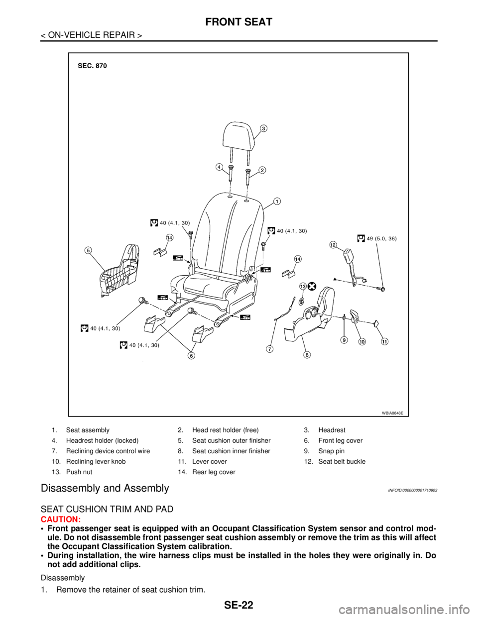
1. Seat assembly 2. Head rest holder (free) 3. Headrest
4. Headrest holder (locked) 5. Seat cushion outer finisher 6. Front leg cover
7. Reclining device control wire 8. Seat cushion inner finisher 9. Snap pin
10. Reclining lever knob 11. Lever cover 12. Seat belt buckle
13. Push nut 14. Rear leg cover
WBIA0848E
Page 4674 of 5883
![NISSAN TIIDA 2007 Service Repair Manual VEHICLE SECURITY INDICATOR
SEC-49
< COMPONENT DIAGNOSIS >[WITH INTELLIGENT KEY SYSTEM]
C
D
E
F
G
H
I
J
L
MA
B
SEC
N
O
P
VEHICLE SECURITY INDICATOR
DescriptionINFOID:0000000001404115
Vehicle security NISSAN TIIDA 2007 Service Repair Manual VEHICLE SECURITY INDICATOR
SEC-49
< COMPONENT DIAGNOSIS >[WITH INTELLIGENT KEY SYSTEM]
C
D
E
F
G
H
I
J
L
MA
B
SEC
N
O
P
VEHICLE SECURITY INDICATOR
DescriptionINFOID:0000000001404115
Vehicle security](/manual-img/5/57395/w960_57395-4673.png)
VEHICLE SECURITY INDICATOR
SEC-49
< COMPONENT DIAGNOSIS >[WITH INTELLIGENT KEY SYSTEM]
C
D
E
F
G
H
I
J
L
MA
B
SEC
N
O
P
VEHICLE SECURITY INDICATOR
DescriptionINFOID:0000000001404115
Vehicle security indicator is located on top left side of the instrument panel near the autolight sensor.
NATS (Nissan Anti-Theft System) and vehicle security system conditions are indicated by blink or illumina-
tion of vehicle security indicator.
Component Function CheckINFOID:0000000001404116
1.CHECK FUNCTION
1. Perform “THEFT IND” in the “Active Test” mode with CONSULT-III.
2. Check vehicle security indicator operation.
Is the inspection result normal?
YES >> INSPECTION END.
NO >> Refer to SEC-49, "
Diagnosis Procedure".
Diagnosis ProcedureINFOID:0000000001404117
1.CHECK SECURITY INDICATOR LAMP POWER SUPPLY CIRCUIT
1. Turn ignition switch OFF.
2. Disconnect security indicator lamp connector.
3. Check voltage between security indicator lamp harness connec-
tor and ground.
Is the inspection result normal?
YES >> GO TO 2.
NO >> Repair or replace harness.
2.CHECK SECURITY INDICATOR LAMP SIGNAL CIRCUIT
1. Disconnect Intelligent Key unit connector.
Te s t i t e m D e s c r i p t i o n
THEFT INDON
Vehicle security indicatorON
OFF OFF
ALKIA0846ZZ
Te r m i n a l s
Voltage (V)
(Approx.) (+)
(–)
Security indicator lamp connector Terminal
M31 1 Ground Battery voltage
Page 4694 of 5883
![NISSAN TIIDA 2007 Service Repair Manual BCM (BODY CONTROL MODULE)
SEC-69
< ECU DIAGNOSIS >[WITH INTELLIGENT KEY SYSTEM]
C
D
E
F
G
H
I
J
L
MA
B
SEC
N
O
P
REAR WIPER CONTROL
BCM detects a rear wiper stopping position according to a rear wiper NISSAN TIIDA 2007 Service Repair Manual BCM (BODY CONTROL MODULE)
SEC-69
< ECU DIAGNOSIS >[WITH INTELLIGENT KEY SYSTEM]
C
D
E
F
G
H
I
J
L
MA
B
SEC
N
O
P
REAR WIPER CONTROL
BCM detects a rear wiper stopping position according to a rear wiper](/manual-img/5/57395/w960_57395-4693.png)
BCM (BODY CONTROL MODULE)
SEC-69
< ECU DIAGNOSIS >[WITH INTELLIGENT KEY SYSTEM]
C
D
E
F
G
H
I
J
L
MA
B
SEC
N
O
P
REAR WIPER CONTROL
BCM detects a rear wiper stopping position according to a rear wiper auto stop signal.
When a rear wiper auto stop signal is in the condition listed below, BCM stops power supply to rear wiper after
rear wiper is activated for five seconds.
NOTE:
The above operation is repeated when operating the rear wiper switch one minute after the stop of the rear
wiper caused by Fail-safe.
TURN SIGNAL LAMP CONTROL
BCM detects the turn signal lamp circuit status from the terminal voltage.
BCM increases the turn signal lamp blinking speed if the bulb or harness open is detected with the turn signal
lamp operating.
NOTE:
The blinking speed is normal while activating the hazard warning lamp.
LIGHT & RAIN SENSOR MALFUNCTION DETECTION FUNCTION
BCM controls the following items when LIGHT & RAIN sensor has a malfunction.
Auto Light Control
Headlamp is turned ON.
Front Wiper Control
The condition just before the activation of Fail-safe is maintained until the front wiper switch is turned OFF.
DTC Inspection Priority ChartINFOID:0000000001404126
DTC IndexINFOID:0000000001404127
NOTE:
Details of time display
CRNT: Displays when there is a malfunction now or after returning to the normal condition until turning igni-
tion switch OFF → ON again.
Display contents of CONSULT Fail-safe Cancellation
B2190: NATS ANTENNA AMP Inhibits engine cranking
Inhibits steering lock unlocking (Intelligent Key unit)
Fuel cut (ECM)Erase DTC
B2191: DIFFERENCE OF KEY Inhibits engine cranking
Inhibits steering lock unlocking (Intelligent Key unit)
Fuel cut (ECM)Erase DTC
B2192: ID DISCORD BCM-ECM Fuel cut (ECM) Erase DTC
B2193: CHAIN OF BCM-ECM Fuel cut (ECM) Erase DTC
B2194: DISCORD BCM-I-KEY Inhibits engine cranking
Inhibits steering lock unlocking (Intelligent Key unit)
Fuel cut (ECM)Erase DTC
Ignition switch Rear wiper switch Auto stop signal
ONOFFRear wiper stop position signal cannot be
input 5 seconds.
ON The signal does not change for 5 seconds.
Priority DTC
1 U1000: CAN COMM CIRCUIT
U1010: CONTROL UNIT (CAN)
2 B2190: NATS ANTENNA AMP
B2191: DIFFERNCE OF KEY
B2192: ID DISCORD BCM-ECM
B2193: CHAIN OF BCM-ECM
B2194: DISCORD BCM-I-KEY